2017
Publication Year
2021-02-19T15:58:47Z
Acceptance in OA@INAF
The ATHENA telescope and optics status
Title
Bavdaz, Marcos; Wille, Eric; Ayre, Mark; Ferreira, Ivo; Shortt, Brian; et al.
Authors
10.1117/12.2274776
DOI
http://hdl.handle.net/20.500.12386/30485
Handle
PROCEEDINGS OF SPIE
Series
10399
Number
PROCEEDINGS OF SPIE
SPIEDigitalLibrary.org/conference-proceedings-of-spieThe Athena telescope and optics
status
Marcos Bavdaz
Eric Wille
Mark Ayre
Ivo Ferreira
Brian Shortt
Sebastiaan Fransen
Maximilien Collon
Giuseppe Vacanti
Nicolas Barriere
Boris Landgraf
Jeroen Haneveld
Coen van Baren
Karl-Heintz Zuknik
Desiree Della Monica Ferreira
Sonny Massahi
Finn Christensen
Michael Krumrey
Vadim Burwitz
The ATHENA Telescope and Optics Status
Marcos Bavdaz
1, Eric Wille
1, Mark Ayre
1, Ivo Ferreira
1, Brian Shortt
1, Sebastiaan Fransen
1,
Maximilien Collon
2, Giuseppe Vacanti
2, Nicolas Barriere
2, Boris Landgraf
2, Jeroen Haneveld
3, Coen
van Baren
4, Karl-Heinz Zuknik
5, Desiree Della Monica Ferreira
6, Sonny Massahi
6, Finn
Christensen
6, Michael Krumrey
7, Vadim Burwitz
8, Giovanni Pareschi
9, Daniele Spiga
9, Giuseppe
Valsecchi
10, Dervis Vernani
11, Paul Oliver
12, André Seidel
131 European Space Agency, ESTEC, Keplerlaan 1, PO Box 299, NL-2200 AG Noordwijk, The Netherlands
2 cosine, Oosteinde 36, NL-2361 HE Warmond, The Netherlands
3 Micronit Microfluidics B.V., Colosseum 15, NL-7521 PV Enschede, The Netherlands
4 SRON, Sorbonnelaan 2, NL-3584 CA Utrecht, The Netherlands
5 OHB System AG, Manfred-Fuchs-Straße 1, 82234 Weßling, Germany
6 DTU Space, Elektrovej 328, 2800 Kgs Lyngby, Denmark
7 Physikalisch-Technische Bundesanstalt (PTB), Abbestr. 2-12, D-10587 Berlin, Germany 8 MPI f. extraterrestrische Physik, Giessenbachstrasse 1, D-85748 Garching, Germany
9 INAF Osservatorio Astronomico di Brera, Via E. Bianchi 46 I- 23807, Merate (LC), Italy
10 Media Lario S.r.l., Località Pascolo, I-23842 Bosisio Parini (LC), Italy
11 Thales Alenia Space Switzerland Ltd, Schaffhauserstrasse 580, 8052 Zürich, Switzerland
12 Teledyne e2v, 106 Waterhouse Lane, Chelmsford, Essex CM1 2QU, England
13 Fraunhofer Institute for Material and Beam Technology, Winterbergstrasse 28, D-01277 Dresden, Germany
ABSTRACT
The work on the definition and technological preparation of the ATHENA (Advanced Telescope for High ENergy Astrophysics) mission continues to progress. In parallel to the study of the accommodation of the telescope, many aspects of the X-ray optics are being evolved further.
The optics technology chosen for ATHENA is the Silicon Pore Optics (SPO), which hinges on technology spin-in from the semiconductor industry, and uses a modular approach to produce large effective area lightweight telescope optics with a good angular resolution.
Both system studies and the technology developments are guided by ESA and implemented in industry, with participation of institutional partners. In this paper an overview of the current status of the telescope optics accommodation and technology development activities is provided.
Keywords: X-ray optics, X-ray astronomy, ATHENA, Silicon Pore Optics, X-ray telescopes, X-ray testing, Technology
preparation
1. TECHNOLOGY PREPARATION
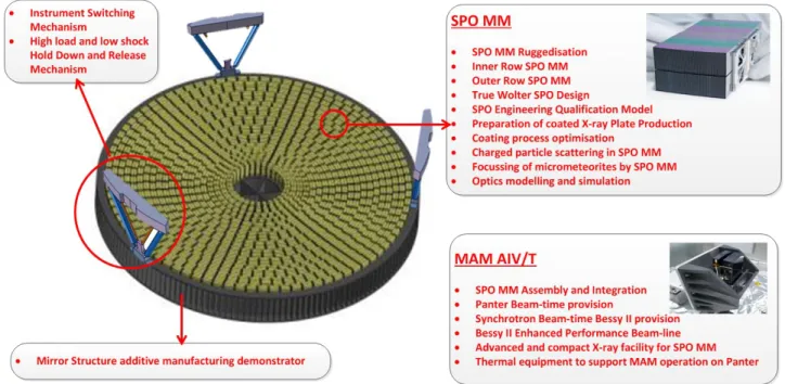
ATHENA [1-4] is the second large class ESA science mission (L2), and is a high energy astrophysics observatory intended to study the hot and energetic universe. The mission combines novel optics with advanced detection systems to achieve an unprecedented performance. System studies (Phase A) are under way, and the required technologies are being developed, aiming to demonstrate the readiness for adoption of the mission for implementation. A Technology Readiness Level of 5/6 is required [5], and correspondingly a large number of technology development activities are currently being undertaken. Figure 1 provides an overview of the technology development activities being undertaken, which address all aspects of the optics, ranging from the additive manufacturing of the monolithic titanium optical bench, over the
Optics for EUV, X-Ray, and Gamma-Ray Astronomy VIII, edited by Stephen L. O'Dell, Giovanni Pareschi, Proc. of SPIE Vol. 10399, 103990B · © 2017 SPIE · CCC code: 0277-786X/17/$18 · doi: 10.1117/12.2274776
Instrument Switching Mechanism
High load and low shock
Hold Down and Release
Mechanism
Mirror Structure additive manufacturing demonstrator
SPO MM
SPO MM Ruggedisation Inner Row SPO MM Outer Row SPO MM True Wolter SPO Design
SPO Engineering Qualification Model Preparation of coated X -ray Plate Production Coating process optimisation
Charged particle scattering in SPO MM Focussing of micrometeorites by SPO MM Optics modelling and simulation
MAM AIV/T
SPO MM Assembly and Integration
Panter Beam -time provision
Synchrotron Beam -time Bessy II provision Bessy II Enhanced Performance Beam -line Advanced and compact X -ray facility for SPO MM
Thermal equipment to support MAM operation on Panter
ruggedizing and performance increase of the mirror elements, to the X-ray test facilities [6-9] required to verify the performance. In the following some further details are provided on the main areas of development. More detailed information is provided in separate papers of these proceedings.
Figure 1: The ATHENA telescope technology developments are addressing all elements of the optics. Many technology development activities are being implemented in European industry and institutions, building on the existing heritage and technical expertise. The individual activities are closely linked, and are kept connect to the system level studies, ensuring an organic and coherent maturation of the mission design and the required technologies. An associated Technology Development Plan is being regularly updated, adding activities to address any surfacing new requirement.
The ATHENA telescope is based on the Silicon Pore Optics (SPO) technology [10-46], which is able to deliver on the challenging requirements, combining:
• Large effective area • Good angular resolution • Low mass
• Cost effective production.
The SPO technology benefits from the multi-billion Euro investments in the semiconductor industry, and utilises the newest generation of silicon wafers with their superb surface finish as the starting material, and employs equipment and processes perfected for the production of modern electronic devices to create compact X-ray optics Mirror Modules (MM). A decisive element of the SPO is the pore structure geometry, which makes it possible to use very thin mirror substrates (about 170 µm thick) whilst ensuring an excellent figure quality (arc-second slope error).
qnyua ob6LgfIou2 UJILLOL OLI6Uç9flOU cougLolllua glJs UJ6CIJ9U12lJJ OL póxgboq gsblcgsq) 5 141142 u.wognls2 (oulA UJILLOL (3x) IUf6LE9C62
we2E\w2
Ong6LLIUJ 2gLncfnLs UJILLOL (18x) Iu16149c62 Pg416\W2 lJ6LUJgl HDtSW P!boq UJOnug6q g2 ogw)UJILLOL (UOg maps'
O4J6L 21q6 Ot fps
29LfL9Cl<6L (21b) ou 2A46LU (OBW) guq pupogLq W6gLoloaA
10L IJJILLOL uJognló2 (IAN)
Iuf6aL9g6q M6p MIgIJ bOCIC6g2
UJILLOL 2gLnCgnL6 (142) MIgJ
MIgIJ aILg6L2
Lgglgl 2bgL
2. TELESCOPE STRUCTURE AND ACCOMMODATION
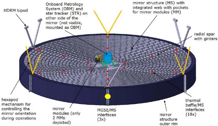
With its large size the ATHENA telescope optics dominates the bottom part of the ATHENA spacecraft in launch configuration. A stable and stiff structure is required to hold the many Silicon Pore Optics (SPO) Mirror Modules (MM) safely co-aligned during all the ground handling, the launch sequence and the operations in space. The Mirror Structure (MS) is shown in figure 2, including the two hexapod systems, which provide the interface to the spacecraft. One of these hexapods is used to support the launch loads (and ground handling), and is released once in orbit, transferring to the second hexapod, which is articulated and permits to align the optics to the active detector. The two focal plane instruments are very large and complex, and are therefore fixed in position, and a tilting of the telescope optics is used to select the instrument to be used. The articulation of the optics also allows for lateral positioning and accurate focusing in orbit. An on-board metrology system tracks the relative position of the optics, and therefore of the optical axis and focal position, with respect to the detector instruments. The star trackers are mounted on the opposite side of the MS, ensuring a rigid and stable connection to the optics and the metrology system.
Figure 2: Overview of the ATHENA Mirror Structure (MS) and its interfaces to the spacecraft and auxiliary systems. The side facing the detector instruments is shown, and only two Mirror Modules (MM) are depicted. The structure has to maintain the co-alignment of the hundreds of mirror modules throughout launch and operations in space. The mirror structure is supported by two sets of hexapods. The first is used during the spacecraft handling on ground and the launch sequence, and is released once in orbit. The second hexapod is articulated using a dedicated mechanism in each of its legs, and is used during the in-orbit operations, serving to point the optical axis of the optics to the active instrument. An on-board metrology system is used to track the actual orientation of the ATHENA optics with respect to the detector instruments. The star trackers for the spacecraft attitude control system are also mounted to the center of the mirror structure (not visible in this drawing). HDRM refers to the Hold Down and Release Mechanism, and MGSE to the Mechanical Ground Support Equipment.
The MMs are isostatically mounted to the MS using three dowel pins, and are arranged on a spherical surface with a radius equal to the focal length of the telescope (12 m), centred on the intersection of the optical axis with the focal
0'S2w
L9q!n20-'2w)
ginong6.
2 substrate feedplane. As illustrated in figure 3, showing a cross section of the MS along its radius, the MMs are densely packed and cover radii between 0.25 and 1.5 m in the current baseline design. The length of the MM varies with the radius, according to the varying incidence angles of the incoming radiation onto the con-focally arranged mirrors. All MMs are self-baffling by design, and consist of con-focal mirror plates in a Wolter-I configuration.
Figure 3: The Silicon Pore Optics (SPO) Mirror Modules (MM) are attached to the Mirror Structure (MS) via an isostatic mount, employing three dowel pins per MM. The principal surface of the telescope is a sphere with a radius f = 12 m, centred at the intersection of the optical axis with the focal plane.
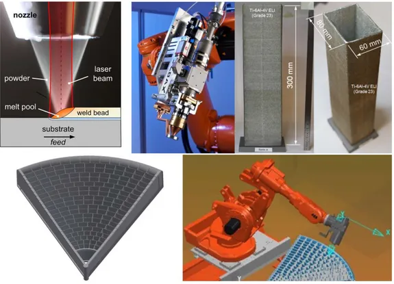
Titanium was found to be the most suitable material for the large monolithic MS. In view of the complexity of the required structure, the tight requirements on the tolerances, and the size of the item, additive manufacturing of titanium was identified as a critical technology. A development activity was initiated, with the task of producing a demonstrator using Laser Metal Deposition (LMD) with powder. In this method a computer defined shape can be manufactured layer by layer, with the filler material (metal powder) being delivered into the process zone, subsequently pre-heated in the laser beam and finally absorbed in the laser induced melt pool (see figure 4, top left).
Figure 4: Laser Metal Deposition (LMD) with titanium powder will be used to produce the MS. High quality material can be deposited under computer control, employing sophisticated monitoring and control systems in the deposition head (see top left for schematic and top middle for photo). Samples representative for the required SPO pocket structure have been successfully produced (see top right). A 60º segment will be made (see bottom left), and the equipment suitable for producing the complete MS will be set up. The deposition head is accurately positioned using a robotic system (see bottom right).
CCD camera 12m Mirror Structure UV light so 03m ce Parabolic Mirror
After solidification the deposited material is generally characterized by a strong metallurgical bonding to the substrate, almost complete avoidance of porosity and continuous material properties. Figure 4, top right, shows demonstration samples, with dimensions and geometry representative for the required SPO MM pockets.
The high quality of the deposited material is assured by specialised process monitoring systems tailored to the titanium additive process (see figure 4, top middle). These systems make use of highly sensitive cameras in combination with intelligent image processing systems and the appropriate control algorithms. The LMD process excels at high process speeds and large part dimensions, compared to powder bed processes. A multi-axis robotic system is used to position the deposition head (see figure 4, bottom right). The equipment will be capable of producing the complete MS for ATHENA, and a 60º segment will be made initially.
3. INTEGRATION OF MIRROR MODULES INTO SUPPORT STRUCTURE
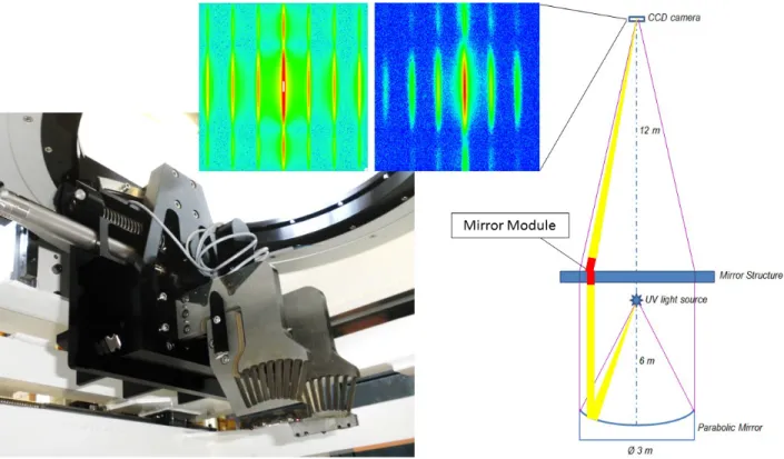
The MMs have to be accurately mounted to the MS, ensuring that all MMs share the same focus. This co-alignment has to be maintained throughout the lifetime of the mission, and must be able to sustain the launch loads and the environmental conditions during the observations in space. The integration process must be efficient and cost effective at the same time, and a large number of MMs has to be integrated under a tight schedule. Therefore, two competitive and technically different methods of integrating the MMs are being explored by two independent industrial consortia. The first method relies on alignment of the MMs in UV light, and is the method used for many prominent X-ray space telescopes (figure 5). Much experience and heritage has been accumulated with this method, but mostly on rotational symmetrical optics systems.
Figure 5: Alignment of MMs using UV light at 218 nm is being demonstrated using a vertical facility, schematically depicted at the right (for the demonstration the beam is additionally folded). This is the method of heritage for aligning X-ray optics systems for space telescopes, and it could be shown that it is also valid for off-axis elements like individual SPO MMs. The top images show the simulated (left) and measured (right) images of the diffraction pattern at the focus of the MM. On the left the MM alignment tool is shown, designed specifically to the requirements of the ATHENA MM integration.
Alignment of
theist MM Bonding oftheist MM
INDIRECT METROLOGY
Abgnmmt nf _'I
Anuo-1ór tnd MM \'acuum Xmivsurrcm"iTt vfuvam-to Mraammnnt Air uf the 2d [UM polYttat Mr-to. Vacuum Allgntttr 1 or Ile eoI MM VaNUm-to Av Bonding col the 2nd MM DIRECT X -RAY
Curing VvuotAir -eo x -ray peno vaavureitenl
The SPO MMs individually are off-axis elements (contrary to the complete ATHENA telescope, which is rotationally symmetric). Hence one of the first tasks undertaken under this activity was the investigation of the exact diffraction properties of the SPO optics under UV light, and the comparison with X-ray alignment. Extensive simulations and measurements in UV and X-ray light have been performed, and showed very good agreement. Figure 5 centre shows the simulated (left) and measured (right) images of the diffraction pattern at 218 nm.
A vertical optical bench is used, with a collimated vertical UV beam, and specially designed and built equipment is used to very precisely position the MM, until its focus is located at exactly the required position, as measured with a UV sensitive camera. The schematic is shown on the right of figure 5, and the positioning equipment on the left.
The second activity (figure 6) uses both indirect metrology, relying on metrology on fiducials attached to the MM and reference measurements performed during the assembly of the MMs at the synchrotron facility, and alignment under direct X-ray illumination. The advantage of the direct X-ray alignment is obviously the minimisation of possible error terms, by aligning the MMs using the wavelength they are built for. This method requires manipulation of the MMs in vacuum, and the availability of a suitable X-ray facility. In this activity this alignment approach will be demonstrated at the PANTER X-ray test facility of the Max-Planck-Institut für extraterrestrische Physik.
Figure 6: The second method of integrating the MMs into the MS relies on indirect optical metrology using laser trackers with autocollimation capability and optical references attached to the MM, and in addition on direct X-ray metrology. In the first step, the orientation and position of the X-ray optical axis and focal position of the MM is measured using synchrotron radiation, and referenced to the optical references on the MM. In the second step, these references are used to (pre)-align the MM inside the PANTER facility, where the final alignment is made using direct X-ray illumination. Top right shows the laser tracker at the X-ray Pencil Beam Facility XPBF 2.0 facility [9] for MM testing with synchrotron radiation, and the left illustrates the MM positioning at PANTER.
The characterization of the mirror modules with laser trackers is foreseen at the new 12 m beamline XPBF 2.0 (described in section 5) in the PTB laboratory at the BESSY II synchrotron radiation facility (see figure 6, top right). The same facility is used to assemble the MMs, simplifying the logistics. The position and orientation of the X-ray optical axis and the focal position of the MM is determined using the synchrotron beam, and is accurately referenced to optical references attached to the MM. Two laser trackers with autocollimation capabilities are used for this purpose.
In the following, the MM is transferred to the PANTER facility, where the indirect metrology now permits the ‘blind’ (i.e. without using the optical properties of the MM itself) alignment of the MM with respect to the desired focal
position. After evacuation of the PANTER vacuum chamber the final alignment of the MM can be accomplished using the X-ray illumination, and observing the X-ray focus of the MM. The positioning equipment is shown on the left of figure 6, and the alignment sequence on the bottom.
Each of the integration demonstration activities will undertake to integrate (i.e. insert, align and fix) two real SPO MMs in a representative MS element, and then verify the alignment at the PANTER facility, employing X-rays.
4.
PRODUCTION OF MIRROR MODULES
The SPO MMs form the core of the ATHENA telescope, and most technology preparation effort is focused in their further development. The activities are focused on improving the angular resolution of the optics, the further automation of their production, and the demonstration of their robustness and environmental compatibility. Work is progressing simultaneously on three MM types, corresponding to the inner-most, a representative middle, and the outermost radius. All aspects of the MM production are being constantly improved, from the production of the individual mirror plates, over the precise stacking to mirror stacks to the assembly of MMs. The required starting materials, processes and procedures, tools and equipment, soft- and hardware, product assurance approach and programmatic issues are all in the spotlight of the developments.
The developments on the middle radius have started first, and have until lately, for historical reasons, worked with a focal length of 20 m (the inner and outer radius MM activities started right away with a 12 m focal length). On 20 mirror plate ray Optical Units (XOUs, i.e. Wolter-I elements consisting of a primary and a secondary stack in series) the X-ray optical performance has been measured by independent teams at two independent X-X-ray facilities (XPBF and PANTER), with the following results:
XPBF
100% of area at 12.8” HEW (comparable to the XMM Newton optics) 69% of area at 9.9” HEW (masking the left and right sides of the optics) 50% of area at 6.6” HEW (masking the front and back of the mirror plates) PANTER
100% of area at 12.8” HEW
70% of area at 8.0” HEW (masking the left and right sides of the optics) 10% of area at 5” HEW (masking the left and right sides of the optics)
In addition, also ancillary goals were achieved, increasing the mirror plate production capacity and reducing the stacking time.
With these results the middle radius was switched from f=20 m (previous IXO hardware heritage) to f=12 m, and starting in September 2016 the first stacks for 12 m focal length have been manufactured and tested. The opportunity was taken to undertake further modifications of the production equipment, replacing R&D electronics and hardware with industrial grade equivalents, cleaning up and modernizing the control software, replacing and adding further on-line metrology, and automating further production steps and sequences. In particular, also vacuum dies have been replaced with electrostatic dies, offering a better control of the pre-forming of the mirror plates before bonding to the stack. Overall the production speed was increased, and the process variations reduced.
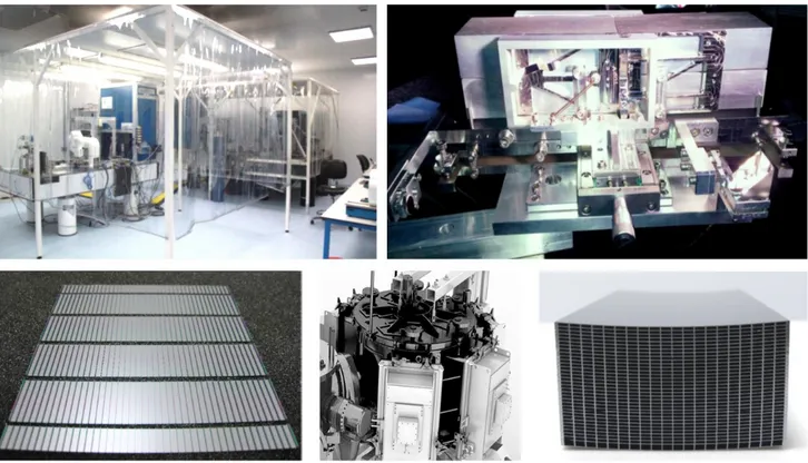
Figure 7 shows the cleanroom hosting the three stacking robots dedicated to the three radii (top left), the new MM assembly tool for the innermost radius (top right), a set of mirror plates produced off a single mother plate for the outermost radius (bottom left), the new industrial grade coating machine currently in production, and the first stack of 35 innermost radius plates with increased rib spacing. In order to reduce the overall development risk, and to increase the progress, innovations are typically introduced on only one the three radii (where the advantage is most prominent), and refined until proved to be a mature benefit, before being transferred also to the other radii.
`wat
I
SS\
s
111111111111M
/ I/I
I 1ft= -=11
a===aggEMEMMIE1
-z-I=OMME=MELIEMEME - me ga=ansm==s==EE-3 FENN iiiiMmaraES ===== amasaaFigure 7. The further development of the SPO MM technology has progressed on several fronts, working on three radii simultaneously, but with separate and dedicated equipment. Top left shows the cleanroom hosting the three stacking robors (innermost, middle and outermost radius), top right the assembly tool for innermost radius MMs, lower left a set of outermost mirror plates produced off a single mother plate, bottom middle the industrial grade coating machine being procured, and bottom right shows a 35 plate stack for the innermost MM.
5. VERIFICATION, QUALIFICATION AND TESTING
The improvements and developments in production of the MMs is being accompanied by enhancements and progress in metrology and testing. Some of this metrology is part of the production equipment, in particular the stacking robots, other regard dedicated measurements for quality inspections, component tests, performance characterisation and environmental qualification.
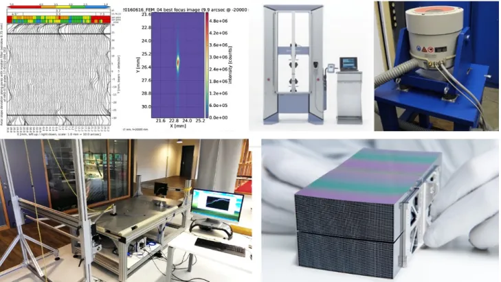
Good progress was made in achieving a good correlation between the fringe reflection metrology installed on each of the stacking robots, and the X-ray measurements performed using synchrotron radiation (see figure 8 top left, showing the topogramme measured using the fringe reflection metrology system present on each of the stacking robots, and the PSF measured using synchrotron radiation).
The installation of the environmental test equipment could be completed, with a computerised pulling station and suitable shaker now fully commissioned (top centre and top right in figure 8). A significant time saver is the shock table, tuned to the requirements of the ATHENA optics, and which regular tests are performed, mostly also employing high speed cameras in addition to the accelerometer sensors (bottom left in figure 8). The completed MMs (figure 8, bottom right) are characterised in terms of X-ray performance at the XPBF and PANTER facilities.
1'4
Ou
LS ID
isa
(0160616 FEM 04 best focus ima
15.70.15 21.6 22.8 24.0 e (9.9 arcs. e-20000 4.8e+06 4.2e+06 3.6e+06_, 3.0e+068 2.4e+06i. 1.8e+06 1.2e+06 16.0e+05 IS 10 -s z g 25.2 A26.4 27.6 28.8 30.0 0.0e+00 21.6 22.8 24.0 25.2 nvo.f.X400 ow
Figure 8: The production of the SPO MM is accompanied with extensive metrology, starting with component level and part inspection tests, and finishing with X-ray performance characterisations. Top left shows the topogramme measured with the on-line fringe reflection metrology system installed on each of the stacking robots, centre left shows the PSF of a MM measured at XPBF. Top centre right: automatic pulling station for component tests, top right: shaker, bottom left shock table, bottom right: completed MM.
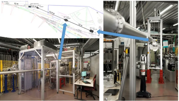
With the improving performance and production rate of the SPO MMs, also the X-ray testing and characterisation capabilities had to improve. A new X-ray parallel beam facility (XPBF 2.0) has been installed in the laboratory of the Physikalisch-Technische Bundesanstalt at the synchrotron radiation facility BESSY II in Berlin. The new beamline provides a pencil beam of very low divergence, a vacuum chamber with a hexapod system for accurate positioning of the SPO to be investigated, and a vertically movable CCD-based camera system to register the direct and the reflected beam. In contrast to the existing beamline, a multilayer-coated toroidal mirror is used for beam monochromatization and collimation, enabling the use of beam diameters between about 100 µm and several mm at a photon energy of 1.6 keV. The new beamline features increased travel ranges for the hexapod to cope with larger SPOs and a sample to detector distance of 12 m corresponding to the focal length of ATHENA.
Figure 9 shows the floor plan of the new beamline (top left), indicating the dimensions and the location of the optics sample chamber (bottom left) and the detector tower (photo on the right).
Figure 9: A new beamline was installed in the laboratory of the Physikalisch-Technische Bundesanstalt at the synchrotron radiation facility BESSY II, providing a collimated beam of up to a few mm in diameter, and featuring a larger experiment (optics) chamber and larger sample travel range. Top left: floor plan, showing the main dimensions and location of the optics sample chamber (bottom left) and of the detector tower (photo on the right).
6. CONCLUSION
The Silicon Pore Optics technology is maturing further, and developments are progressing steadily on all fronts. A technology plan is in place and is being regularly updated, covering a wide area of activities, ranging from component developments, over production equipment improvements to test and characterisation facility expansions.
Work on three different Mirror Modules (MM) is continuing to advance in parallel, addressing the individual challenges of the innermost, the midrange and outermost radius MMs. Innovations are selectively introduced, and transferred to the other radii once validated. The integration of the MMs into the Mirror Structure (MS) is being developed in two independent activities, employing two alternative methods. The MS is envisaged to be produced by additive manufacturing, and a corresponding technology activity has started.
The priorities remain the improvement of the angular resolution, the further automation of the production process, and the environmental qualification of the optics.
ACKNOWLEDGEMENTS
The work presented in this paper was accomplished in a collaborative effort, involving many individuals, companies and institutions. All these contributions are greatly appreciated by the authors.
REFERENCES
[1] Ayre, M., et al, “ATHENA – System design and implementation for a next generation x-ray telescope”, Proc. of SPIE Vol. 9601, 96010L (2015)
[2] ESA, [ATHENA: Assessment of an X-Ray Telescope for ESA Cosmic Vision Program], CDF-150(A), (2014)
[3] Nandra, P. et al, “ATHENA : The Advanced Telescope for High-Energy Astrophysics”, http://www.the-athena-x-ray-observatory.eu/
[4] Ayre, M., et al, “ATHENA: system studies and optics accommodation”, Proc. SPIE 9905, 990526 (2016)
[5] ISO, “Space systems - Definition of the Technology Readiness Levels (TRLs) and their criteria of assessment”, ISO 16290, The International Organization for Standardization (2013)
[6] Krumrey, M. et al, “X-ray pencil beam facility for optics characterization”, Proc. SPIE 7732, 77324O (2010).
[7] Freyberg, M. et al., "Potential of the PANTER x-ray test facility for calibration of instrumentation for XEUS", Proc. SPIE 6266, 62663H (2006).
[8] Burwitz, V., et al, “In focus measurements of IXO type optics using the new PANTER X-ray test facility extension”, Proc. of SPIE Vol. 8861, 88611J (2013)
[9] Krumrey, M. et al, “New X-ray parallel beam facility XPBF 2.0 for the characterization of silicon pore optics”, Proc. SPIE. 9905, 99055N. (2016)
[10] Bavdaz, M. et al., "Progress at ESA on high-energy optics technologies", Proc. SPIE 5168, 136-147 (2004).
[11] Beijersbergen, M. et al., "Development of x-ray pore optics: novel high-resolution silicon millipore optics for XEUS and ultralow mass glass micropore optics for imaging and timing", Proc. SPIE 5539, 104-115 (2004).
[12] Beijersbergen, M. et al., "Silicon pore optics: novel lightweight high-resolution X-ray optics developed for XEUS", Proc. SPIE 5488, 868-874 (2004).
[13] Kraft, S. et al., "Development of modular high-performance pore optics for the XEUS x-ray telescope", Proc. SPIE 5900, 297-308 (2005).
[14] Günther, R. et al., "Production of silicon pore optics", Proc. SPIE 6266, 626619 (2006).
[15] Collon, M. J. et al., "Performance characterization of silicon pore optics", Proc. SPIE 6266, 62661T (2006).
[16] Collon, M. J. et al., "Metrology, integration, and performance verification of silicon pore optics in Wolter-I configuration", Proc. SPIE 6266, 626618 (2006).
[17] Graue, R. et al., "Assembling silicon pore optics into a modular structure", Proc. SPIE 6266, 62661U (2006). [18] Wallace, K. et al, “Silicon pore optics development”, Proc. SPIE 7437, 7437 (2009).
[19] Kampf, D. et al., “Optical bench elements (petals) for IXO”, Proc. SPIE, 7437 (2009). [20] Collon, M. J. et al, “Stacking of silicon pore optics for IXO”, Proc. SPIE, 7437 (2009).
[21] Ackermann, M et al, “Performance prediction and measurement of silicon pore optics”, Proc. SPIE, 7437 (2009). [22] Vacanti, G, et al., “Silicon pore optics for astrophysical missions”, Proc. SPIE, 7732, 77324O (2010).
[23] Collon, M. J. et al, “Stacking of Silicon Pore Optics for IXO”, Proc. SPIE 7732, 77321F (2010). [24] Bavdaz, M., “ESA optics technology preparation for IXO”, Proc. SPIE 7732, 77321E (2010).
[25] Wille, E, et al, “Mass Production of Silicon Pore Optics for IXO and ATHENA”, Proc. of SPIE 8147, 81470E1(2011) [26] Collon, M, et al, “Design, Fabrication, and Characterization of Silicon Pore Optics for ATHENA/IXO”, Proc. of SPIE
8147, 81470D1(2011)
[27] Bavdaz, M. et al., “ESA led ATHENA/IXO optics development status”, Proc. of SPIE 8147, 81470C1(2011) [28] Bavdaz, M, et al, “Silicon Pore Optics developments and status”, Proc. of SPIE 8443, 844329(2012)
[29] Ackermann, M, et al, “Novel applications of Silicon Pore Optics technology”, Proc. of SPIE 8443, 84430V(2012) [30] Bavdaz, M., et al, “X-ray optics developments at ESA”, Proc. of SPIE Vol. 8861, 88610L (2013)
[31] Collon, M., et al, “Aberration-free Silicon Pore X-ray Optics”, Proc. of SPIE Vol. 8861, 88610M (2013)
[32] Wille, E., et al, “Stray Light Baffling and Environmental Qualification of Silicon Pore Optics”, of SPIE Vol. 8861, 88611E (2013)
[33] Willingale, R. et al, “Science requirements and optimization of the silicon pore optics design for the ATHENA mirror”, Proc. of SPIE Vol. 9144, 91442E (2014)
[34] Bavdaz, M. et al, “Preparing the optics technology to observe the hot universe”, Proc. of SPIE Vol. 9144, 91442F (2014) [35] Collon, M. et al, “Making the ATHENA optics using Silicon Pore Optics”, Proc. of SPIE Vol. 9144, 91442G (2014) [36] Wille, E. et al, “Qualification of Silicon Pore Optics”, Proc. of SPIE Vol. 9144, 91442H (2014)
[37] Bavdaz, M. et al, “The ATHENA Optics”, Proc. of SPIE Vol. 9603, 96030J (2015)
[38] Collon, M. et al, “Silicon Pore Optics development for ATHENA”, Proc. of SPIE Vol. 9603, 96030K (2015)
[40] Vacanti, G., et al, “New ray-tracing capabilities for the development of Silicon Pore Optics”, Proc. of SPIE Vol. 9603, 96030G (2015)
[41] Della Monica Ferreira, D. et al., “Coating Optimisation for the ATHENA+ mission”, Proc. Of SPIE Vol.8861, 886112 (2013)
[42] Massahi S., et al, “Investigation of Photolithography Process on SPOs for the ATHENA Mission”, Proc. of SPIE Vol. 9603, 96030M (2015)
[43] Bavdaz, M., et al, “The ATHENA optics development”, Proc. SPIE 9905, 990527 (2016)
[44] Collon, M., et al, “Silicon pore optics for the ATHENA telescope”, Proc. SPIE 9905, 990528 (2016) [45] Wille, E., et al, “Mass production of silicon pore optics for ATHENA”, Proc. SPIE 9905, 990529 (2016)
[46] Spiga, D., et al, “Simulation and modelling of silicon pore optics for the ATHENA x-ray telescope”, Proc. SPIE. 9905, 99055O (2016)