• Non ci sono risultati.

Model Checking Cyber-Physical Systems

N/A
N/A
Protected

Academic year: 2021

Condividi "Model Checking Cyber-Physical Systems"

Copied!
118
0
0

Testo completo

(1)

Università degli Studi di Salerno

Dottorato di Ricerca in Informatica e Ingegneria dell’Informazione

Ciclo 31 – a.a 2017/2018

T

ESI DI

D

OTTORATO

/

P

H

.D.

T

HESIS

Model Checking Cyber-Physical

Systems

YOUSSEF DRIOUICH

S

UPERVISOR

:

PROF. DOMENICO PARENTE

P

H

D

P

ROGRAM

D

IRECTOR

: PROF. PASQUALE CHIACCHIO

Dipartimento di Ingegneria dell’Informazione ed Elettrica

e Matematica Applicata

(2)
(3)

Abstract

Cyber-Physical Systems (CPSs) are integrations of computation

with physical processes. Applications of CPS arguably have the

potential to overshadow the 20-th century IT revolution.

Nowa-days, CPSs application to many sectors like Smart Grids,

Trans-portation, and Health help us run our lives and businesses smoothly,

successfully and safely.

Since malfunctions in these CPSs can have serious, expensive,

sometimes fatal consequences, Simulation-based Verification (SBV)

tools are vital to minimize the probability of errors occurring

dur-ing the development process and beyond. Their applicability is

supported by the increasingly widespread use of Model Based

De-sign (MBD) tools. MBD enables the simulation of CPS models

in order to check for their correct behaviour from the very initial

design phase. The disadvantage is that SBV for complex CPSs

is an extremely resources and time-consuming process, which

typ-ically requires several months of simulation. Current SBV tools

are aimed at accelerating the verification process with multiple

simulators working simultaneously. To this end, they compute all

the scenarios in advance in such a way as to split and simulate

them in parallel. Nevertheless, there are still limitations that

pre-vent a more widespread adoption of SBV tools. To this end, we

present a MBD methodology aiming the acausual modeling and

verification via formal-methods, specifically the model checking

techniques, the system under verification (SUV). Our approach

relies basically on: Firstly, the analysis of the steady-states of the

CPS and the bounding technique of the system’s state in

paral-lel with the simulation in order to identify the state space of the

(4)

system simulating it only once, then represent it as a Finite State

Machine (FSM). Secondly, exhaustively verify the resulted FSM

using a symbolic model checker and express the desired properties

in classical temporal logic. The application to a power

manage-ment system is presented as a case study.

(5)

Sommario

I sistemi ciberfisici (CPS) sono integrazioni del calcolo con i

pro-cessi fisici. Le applicazioni dei CPS probabilmente hanno il potere

di sovrastare la rivoluzione IT del XX secolo. Oggigiorno, l’applicazione

dei sistemi ciberfisici a molti settori come Smart Grid, trasporto

e salute, ci aiuta a gestire le nostre vite e le nostre attivit`

a senza

problemi, con successo e in sicurezza.

Poich´

e i malfunzionamenti in questi sistemi ciberfisici possono

avere conseguenze gravi, costose e talvolta fatali, gli strumenti

di verifica basata sulla simulazione (SBV) sono fondamentali per

ridurre al minimo la probabilit`

a di errori che si verificano durante

il processo di sviluppo e oltre. La loro applicabilit`

a `

e

suppor-tata dall’uso sempre pi`

u diffuso di strumenti Model Based

De-sign (MBD). MBD consente la simulazione di modelli CPS al fine

di verificare il loro corretto comportamento sin dalla fase di

pro-gettazione iniziale. Lo svantaggio `

e che la verifica basata sulla

simulazione per CPS complessi `

e un processo estremamente

dis-pendioso in termini di tempo e risorse, che in genere richiede

di-versi mesi di simulazione. Gli attuali strumenti SBV mirano ad

accelerare il processo di verifica con pi`

u simulatori che lavorano

simultaneamente. A tal fine, calcolano tutti gli scenari in anticipo

in modo tale da suddividerli e simularli in parallelo. Tuttavia,

es-istono ancora limitazioni che impediscono un’adozione pi`

u diffusa

degli strumenti di verifica basata sulla simulazione. A tal fine,

presentiamo una metodologia MBD che mira alla modellazione

e alla verifica acausual tramite metodi formali, in particolare le

tecniche di model checking, il sistema sotto verifica. Il nostro

ap-proccio si basa essenzialmente su: In primo luogo, l’analisi degli

(6)

stati stazionari del CPS e la tecnica di delimitazione dello stato

del sistema in parallelo con la simulazione al fine di identificare lo

spazio dello stato del sistema simulandolo solo una volta, quindi

rappresentarlo come una macchina a stati finiti(FSM). In secondo

luogo, verificare esaurientemente l’FSM risultante utilizzando un

symbolic model checker ed esprimere le propriet`

a desiderate nella

logica temporale classica. L’applicazione a un power management

system viene presentata come caso di studio.

(7)

Acknowledgements

Firstly, I would like to express my sincere gratitude to my

ad-visor prof. Domenico Parente for the continuous support of my

Ph.D study and related research, for his patience, motivation, and

knowledge. His guidance helped me in all the time of research and

writing of this thesis.

Besides my advisor, I would like to thank prof. Enrico Tronci for

his insightful comments and encouragement, but also for the hard

question which incented me to widen my research from various

perspectives.

I would also like to thank the committee members, Dr.

Toni

Mancini, prof. Francesco Basile and prof. Gabriel Alfonso Rinc´

on-Mora for serving as my committee members even at hardship.

A special thanks goes to Fabio, Angela, Cristina, Carmen and

Giuseppe for their great help and assistance.

I would also like to thank my girlfriend Maria Rosaria for

support-ing me, I can’t thank you enough for encouragsupport-ing me throughout

this experience.

Last but not the least, I would like to thank my family: my

par-ents, my brother Ilias and my sister Imane for supporting me

spir-itually throughout writing this thesis and in my life in general,

words can not express how grateful I am, they are the most

im-portant people in my world and I dedicate this thesis to them.

(8)
(9)

Contents

1

Introduction

3

1.1

Cyber-Physical Systems

. . . .

3

1.2

Model Based Design

. . . .

5

1.2.1

System’s Definition . . . .

6

1.2.2

Simulate, Validate and Verify . . . .

7

1.3

System Verification . . . .

8

1.3.1

Simulation-Based Verification . . . .

9

1.3.2

Formal Method-Based Verification . . . .

10

1.4

State of the Art . . . .

11

1.4.1

Formal Methods . . . .

11

1.4.2

Run-Time Verification . . . .

13

1.4.3

Model-Based approach . . . .

14

1.5

Thesis Focus and Contributions . . . .

15

1.6

Outline . . . .

15

2

Preliminaries

17

2.1

Synchronous Models . . . .

17

2.2

Properties of Components . . . .

18

2.3

Safety Requirements . . . .

20

2.4

Simulation . . . .

21

2.5

Verification

. . . .

22

3

CPS Modeling for Formal-method Based

Verifica-tion

25

3.1

Methodology

. . . .

26

3.1.1

Analysis of the steady-state . . . .

26

(10)

3.1.2

Finite Transition System Definition . . . . .

28

3.2

Steps of the Algorithm . . . .

29

3.3

Conclusion . . . .

33

4

Model Verification

35

4.1

Model Checking . . . .

35

4.2

Model checking tools . . . .

36

4.3

Properties expression . . . .

37

4.4

Model Checking Tool: NuSMV

. . . .

40

4.5

Verification Methodology . . . .

41

4.6

Conclusion . . . .

43

5

Case Study

45

5.1

Types of DMPPT systems . . . .

46

5.1.1

Boost Converter Smart Panel . . . .

46

5.1.2

Buck Converter Smart Panel . . . .

47

5.1.3

Buck/Boost Converter Smart Panel . . . . .

48

5.2

Cyber-Physical Energy System . . . .

49

5.2.1

Physical Modeling

. . . .

49

5.2.2

Control Algorithm

. . . .

50

5.2.3

Computational System . . . .

50

5.3

Modeling the CPS : Modelica . . . .

51

5.3.1

Acausal Modeling . . . .

52

5.3.2

DMPPT Models: . . . .

53

5.4

Benchmark: . . . .

66

5.5

Simulating the CPS : JModelica.org . . . .

67

5.6

Model Checking : NuSMV . . . .

73

5.6.1

Defining the transition system in NuSMV

description language . . . .

73

5.6.2

Verification of the transition system . . . . .

75

5.7

Conclusion . . . .

79

6

Conclusion and Future Works

81

6.1

Conclusions . . . .

81

6.2

Future Works . . . .

82

(11)

Appendix A The Python script of the JModelica.rg

simulation

83

Appendix B The transition rules of the transition

sys-tem

85

Bibliography

94

(12)
(13)

List of Figures

1.1

Cyber-Physical Systems representation . . . .

4

1.2

V-model of MBD . . . .

8

1.3

Simulation-Based Verification Diagram . . . .

10

1.4

Formal Method-Based Verification Diagram

. . . .

11

3.1

Time-domain steady state analysis Algorithm

. . .

30

3.2

Frequency-domain steady state analysis Algorithm .

31

3.3

Definition of the function next() . . . .

32

3.4

Main algorithm . . . .

32

4.1

Model Checking process. . . .

36

4.2

CTL Formulas. . . .

39

5.1

Distributed Maximum Power Point Tracking circuit

49

5.2

Resistor and Capacitor models in Modelica . . . . .

53

5.3

Simple circuit using the Resistor and Capacitor

mod-els . . . .

53

5.4

JModelica.org architecture . . . .

68

5.5

Plots of the simulation results using the pyplot

pack-age

. . . .

70

(14)
(15)

The seeker after truth is not one who studies the writings of the

ancients and, following his natural disposition, puts his trust in

them, but rather the one who suspects his faith in them and

questions what he gathers from them, the one who submits to

argument and demonstration and not the sayings of human

beings whose nature is fraught with all kinds of imperfection and

deficiency. Thus the duty of the man who investigates the

writings of scientists, if learning the truth is his goal, is to make

himself an enemy of all that he reads, and, applying his mind to

the core and margins of its content, attack it from every side. He

should also suspect himself as he performs his critical

examination of it, so that he may avoid falling into either

prejudice or leniency.

Ibn alHaytham

(16)
(17)

Chapter 1

Introduction

In some key industries, such as defense, automobiles, medical

de-vices, and the smart grid, the bulk of the innovations focus on

cyber-physical systems. A key characteristic of cyber-physical

sys-tems is the close interaction of software components with physical

processes, which impose stringent safety and time/space

perfor-mance requirements on the systems[1] . Cyber-physical systems

are safety-critical since violations of their requirements, such as

missed deadlines or component failures, may have life-threatening

consequences[2]. For example, when a cyber-physical system in a

car detects a crash, the airbag must inflate in less than few

mil-liseconds to avoid severe injuries to the driver. For this reason,

verification activities are performed in parallel with the

develop-ment process, from the initial design up to the acceptance testing

stages.

1.1

Cyber-Physical Systems

A cyber-physical system (CPS) is an integration of computation

with physical processes. Embedded computers and networks

mon-itor and control the physical processes, usually with feedback loops

where physical processes affect computations and vice versa. As

an intellectual challenge, CPS is about the intersection, not the

union, of the physical and the cyber. It is not sufficient to

(18)

sepa-4

1. Introduction

rately understand the physical components and the computational

components. We must instead understand their interaction. The

design of this kind of systems is divided on three main parts:

mod-eling, design, and analysis.

Modeling is the process of gaining a deeper understanding of a

system through imitation. Models imitate the system and reflect

properties of the system.

Models specify what a system does.

Design is the structured creation of artifacts. It specifies how a

system does what it does. Analysis is the process of gaining a

deeper understanding of a system through dissection. It specifies

why a system does what it does (or fails to do what a model says

it should do).

Figure 1.1 Cyber-Physical Systems representation

In the modeling process, we define a system to be a

combina-tion of parts that is considered a whole. A physical system is one

realized in matter, in contrast to a conceptual or logical system

such as software and algorithms. The dynamics of a system is

its evolution in time: how its state changes. A model of a

phys-ical system is a description of certain aspects of the system that

(19)

1.2. Model Based Design

5

is intended to yield insight into properties of the system.

Mod-els have mathematical properties that enable systematic analysis.

The model imitates properties of the system, and hence yields

in-sight into that system. A model is itself a system. It is important

to avoid confusing a model and the system that it models. These

are two distinct artifacts. A model of a system is said to have high

fidelity if it accurately describes properties of the system. It is said

to abstract the system if it omits details. In this work, models of

physical systems inevitably do omit details, so they are always

abstractions of the system. Models of CPS normally include all

three parts. The models will typically need to represent both

dy-namics and static properties (those that do not change during the

operation of the system). Every system must be designed to meet

certain requirements. For CPS, which are often intended for use in

safety-critical, everyday applications, it is essential to certify that

the system meets its requirements. Such system requirements are

also called properties or specifications. It is important to precisely

state requirements to avoid ambiguities inherent in natural

lan-guages. The goal of the many verification techniques is to help

replace descriptive techniques with formal ones, which we believe

are less error prone. Importantly, formal specifications also enable

the use of automatic techniques for formal verification of both

models and implementations.

1.2

Model Based Design

Model-based design (MBD) [3] emphasizes mathematical modeling

to design, analyze, verify, and validate dynamic systems. A

com-plete model of a cyber-physical system represents the coupling of

its environment, physical processes, and embedded computations.

Modeled systems may be tested and simulated offline, allowing

de-velopers to verify the logic of their application, assumptions about

its environment, and end-to-end (i.e. closed-loop) behavior.

The design of a complex cyber-physical system is a challenging

process. Commonly employed design techniques are worldly-wise

(20)

6

1. Introduction

and include mathematical modeling of physical systems, formal

models of computation, simulation of heterogeneous systems,

soft-ware synthesis, verification, validation, and testing. In this work

we have adopted a set of sequential steps that, if followed carefully

and correctly, embraces each of these design techniques and

suffi-ciently rules the development of a complex cyber-physical system.

1.2.1

System’s Definition

Model Physical Processes: A first iteration of physical

mod-eling should take in consideration basic observations and insight

into pertinent physical systems, such as the environment in which

the cyber-physical system operates, or physical processes to be

controlled. Models of physical processes are simplified

represen-tations of real systems, and are usually in the form of systems of

differential equations or continuous equations functions[4]. What

may begin as simple mathematical models may need to be

im-proved following development of a control algorithm, specification

of hardware, and testing of components and subsystems.

Identify the Problem: Recluse fixed parameters, adjustable

pa-rameters, and controlled variables. Identify quantities that

char-acterize physical processes, such as configuration spaces, safety

limitations, input and output sets, saturation points, and modal

behavior. Understand how a physical process may interact with a

computation, for example system requirements, fault conditions,

and reactions to noise and quantization.

Derive a Control Algorithm: Specify the conditions under

which physical processes are controllable and determine a

conve-nient control algorithm to be executed by an embedded computer.

Use the problem characterization to specify requirements on

sam-pling rates, delays, and quantization so that the desired

physi-cal dynamics can be precisely measured and perfectly controlled;

these requirements must be satisfied by the computational

plat-form used. In highly distributed applications, or systems that are

(21)

1.2. Model Based Design

7

generally asynchronous but locally synchronous, it may be

manda-tory to select models of computation before a control algorithm

can be implemented. Reanalyze this step after selecting models

of computation and specifying hardware to determine the impact

of variable sampling estimations introduced by an asynchronous

model of computation, or other nonlinear behaviours in the

phys-ical model.

1.2.2

Simulate, Validate and Verify

Simulate : Deal with the problem using a simulation platform.

If multiple models of computation are to be used, simulation and

synthesis tools must grant the compositions of and interactions

between multiple models of computation. Depending on the

ro-bustness of the development environment, controllers, and

phys-ical processes. Use platform-based design to isolate application

logic and architecture software into interchangeable components,

which can improve code portability, decrease the impact of

chang-ing hardware components, and allow components to be reused in

other applications. Models of individual components and

subsys-tems are as crucial as a complete end-to-end model. Component

models allow a test harness for construction, verification of

syn-thesized software, and testing. If no modeling tool can totally

describe the system, then for each subsystem use the modeling

tool that best captures its dynamics. Countless simulation tools

exist in literature, but most are bounded to only a minor models

of computation and are unable to apprehend the interactions

be-tween heterogeneous systems.

Validate and Verify : Compose suitable parameters to

estab-lish test environments that are as straightforward as possible, and

test each component and subsystem separately. Computational

systems may be isolated from physical systems via

hardware-in-the-loop measurement, where programmable hardware as instance

embedded computers simulate the observation from physical or

other computational processes. Measurements of execution time

(22)

8

1. Introduction

and latency can be used to tune earlier models, and unexpected

test results may lead to erroneous modeling or implementation.

Formal verification and validation give insight into the behavior of

an algorithm over all or certain combinations of its inputs, or over

the course of time. Precisely assert requirements and express them

into a formal specification for verification and validation. List

in-variants that have to be verified during test phase. Verification

and validation are likely the most complicated facets in the design

of a cyber-physical system.

Figure 1.2 V-model of MBD

1.3

System Verification

The principal validation methods for cyber-physical systems are

simulation, testing, deductive verification, and model checking.

Simulation and testing both involve making experiments before

deploying the system in the field. While simulation is performed

on an abstraction or model of the system, testing is performed on

the actual product. In both cases, these methods typically inject

signals at certain points in the system and observe the

result-ing signals at other points. For software, simulation and testresult-ing

usually involve providing certain inputs and observing the

(23)

cor-1.3. System Verification

9

responding outputs. These methods can be a cost-efficient way

to find many errors. However, checking all of the possible

interac-tions and potential pitfalls using simulation and testing techniques

is rarely possibles.

Model checking is a technique generally used for verifying finite

state concurrent systems. One benefit of this restriction is that

verification can be performed automatically. It procedure

nor-mally uses an exhaustive search of the state space of the system

to determine if some specification is true or not. Given sufficient

resources, the procedure will always terminate with a yes/no

an-swer. Moreover, it can be implemented by algorithms with

rea-sonable efficiency, which can be run on moderate-sized machines.

Applying model checking to a design consists of several tasks, each

of which will be discussed in detail later in this thesis.

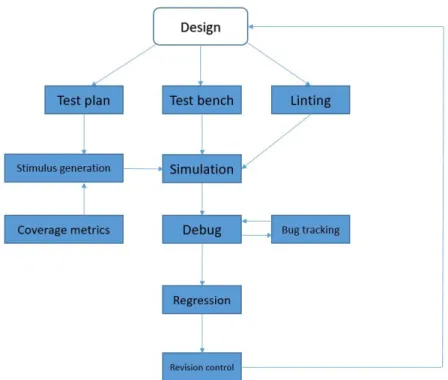
To study verification methodologies further, let’s group

verifica-tion methodologies into two categories: simulaverifica-tion-based and

for-mal method-based verification. The distinguishing factor between

the two categories is the existence or absence of vectors.

Simulation-based verification methodologies rely on vectors, whereas formal

method-based verification methodologies do not. Another way to

distinguish simulation-based and formal method based

verifica-tion is that simulaverifica-tion is input oriented (for example, the designer

supplies input tests) and formal method verification is output

ori-ented (for example, the designer supplies the output properties to

be verified). There is a hybrid category called Semi-Formal

Verifi-cation that takes in input vectors and verifies formally around the

neighborhood of the vectors. Because the semi-formal

methodol-ogy is a combination of simulation-based and formal technolmethodol-ogy,

it is not described separately here.

1.3.1

Simulation-Based Verification

The most commonly used verification approach is simulation-based

verification[5]. As mentioned earlier, simulation-based verification

is a form of verification by redundancy. The variant or the

alterna-tive design manifests in the reference output. During

(24)

simulation-10

1. Introduction

based verification, the design is placed under a test bench, input

stimuli are applied to the test bench, and output from the design

is compared with reference output. A test bench consists of code

that supports operations of the design, and sometimes generates

input stimuli and compares the output with the reference output

as well. The input stimuli can be generated prior to simulation

and can be read into the design from a database during simulation,

or it can be generated during a simulation run.

Figure 1.3 Simulation-Based Verification Diagram

1.3.2

Formal Method-Based Verification

The formal method-based verification methodology differs from

the simulation-based methodology in that it does not require the

generation of test vectors; otherwise, it is similar. Formal

veri-fication can be classified further into two categories: equivalence

checking and property verification. In this thesis, the property

(25)

ver-1.4. State of the Art

11

ification is highlighted, especially the model checking techniques.

Property checking takes in a design and a property which is a

par-tial specification of the design, and proves or disproves that the

design has the property. A property is essentially a duplicate

de-scription of the design, and it acts to confirm the design through

redundancy. A program that checks a property is also called a

model checker, referring the design as a computational model of a

real circuit.

Figure 1.4 Formal Method-Based Verification Diagram

1.4

State of the Art

1.4.1

Formal Methods

Static analysis is used to efficiently compute approximate but

sound guarantees about the behavior of a program without

ex-ecuting it [6]. Abstract interpretation relates abstract analysis to

program execution [7] and can be used to compute invariants [8],

[9], [10]; these approaches have been applied in CPS, including in

(26)

12

1. Introduction

flight control software [11] and outer space rovers [12]. In general,

the efficiency and quality of static analysis tools have reached a

level where they can be practically useful in locating bugs that are

otherwise hard to detect via testing. However, for mission-critical

CPS applications (which may contain millions of lines of code that

interact in complex ways with a physical world), existing industry

static analysis tools either do not scale well (e.g., [13]) or tend to

introduce many false positives (e.g., [14], [15], [16]).

Theorem proving has been applied in deductive verification [17],

[18], where validity of the verification conditions are determined.

Theorem provers have also been used for verifying hybrid systems

[19], [20]. Isabelle/HOL [21] has been used to formally verify the

kernel piece of seL4 [22], which is the foundation OS for a highly

se-cure military CPS application. This work shows that, with careful

design, a (critical component of a) complex CPS can be formally

verified by the state of art theorem prover. However, the

require-ment for human intervention and high costs (the total effort for

proof was about 20 person-years, and kernel changes require 1.5–6

person-years to reverify [23]) makes applying theorem proving

im-possible for general-purpose CPS applications, which may contain

millions of lines of code [24] and require much quicker (and less

expensive) changes.

The verification world is overloaded with highly capable model

checkers [25], [26], including those that handle real-time constraints

[27], parametric constraints [28], stochastic effects [29], and

asyn-chronous concurrency with complex and/or dynamic data

struc-tures (though not sharable between concurrent processes) [30], all

of which are common in CPS. Model abstraction and reduction

can make analysis more tractable (and thus more applicable to

CPS) [31], [32], [33], however, error bounds are usually

unquanti-fied, which makes the verification unsafe. While model checking

allows verification to be fully automated, in addition to issues

such as state-explosion, complexity in property specification, and

inevitable loss of representativeness [34], CPS exhibits bugs that

crop up only at run-time based on the physical state of the

de-ployment world; such bugs cannot be captured by model checking

(27)

1.4. State of the Art

13

alone.

It is exceedingly difficult to prove properties of CPS automatically

because of the disconnect between formal techniques for the cyber

and well-established engineering techniques for the physical [35],

[36]. In recent works [37], [38], physical and software processes

are modeled and composed together either as timed automata or

hybrid automata, and the compositional models are verified by

model checkers against correctness properties.

1.4.2

Run-Time Verification

In run-time verification, correctness properties specify all

admissi-ble executions using extended regular expressions, trace matches,

and others formalisms [39]. Temporal logics, especially variants of

LTL [40] are popular in runtime verification. However, basic

tem-poral logics do not capture nonfunctional specifications that are

essential in CPS (e.g., timeouts and latency) and lack capabilities

to deal with the stochastic nature of many CPS applications [41],

[42], [43].

Probabilistic temporal logics such as probabilistic computation

tree logic (PCTL) [44] and continuous stochastic logic (CSL) [45]

have been introduced two decades ago to specify probabilistic

properties, and a subset of CSL [41] and a CSL compatible

lan-guage [43] are used to monitor probabilistic properties at runtime.

These temporal logics lack the capacity to monitor the continuous

nature of the physical part of CPS applications. In [46], a

moni-tor is created for stochastic hybrid systems and a monimoni-torability

theorem is provided. However, there is little discussion of whether

the monitor will impact the system’s functional and nonfunctional

behaviors. In [47], an efficient runtime assertion checking monitor

is proposed for memory monitoring of C programs. This

noninva-sive monitoring is well suited to mission-critical and time-critical

CPS applications.

In summary, the state of art in run-time verification can

poten-tially provide a great supplement to formal methods and

tradi-tional testing in CPS. Many opportunities remain to make

(28)

run-14

1. Introduction

time verification more suitable to the idiosyncrasies of CPS and

approachable to CPS developers. For instance, aspect-oriented

monitoring tools [48] are less intrusive, and their adaptation to

CPS run-time verification may prove more approachable for

de-velopers.

1.4.3

Model-Based approach

In this category, we talk about model-based verification, which

uses formal models to enable (automatic) testing of CPS

appli-cations [49]. We also include simulation-based techniques aimed

at the model analysis of CPS applications [50], [51], [52].

Mod-eling real-time components has been decomposed into behaviors,

their interactions, and priorities on them; reasoning can then

oc-cur layer by layer [53], [54]. In general, such approaches allow

the verification of all system layers from the correctness proof of

the lower layers (i.e., gate-level) to the verification procedure for

distributed applications; such an approach has been used to verify

automotive systems, a key exemplar of CPS [55]. The

practical-ity and costs of development associated with these approaches are

still unknown. While there are many computational and network

simulators that many software engineers may be familiar with, in

the CPS domain, one of the most relevant systems is Simulink,

which is widely deployed in the automotive industry and other

mission critical domains (e.g., avionic applications) [56]. In [57],

A MATLAB toolbox called S-Taliro is created to systematically

test a given model by searching for a particular system trajectory

that falsifies a given property written in a temporal logic.

How-ever, S-Taliro suffers from a memory explosion problem when a

system contains larger specification formulas. MATLAB also

pro-vides Simulink design verifier (SDV) [58] as an extension tool-set

to perform exhaustive formal analysis of Simulink models.

Model-ica Requirements library [59] is an extension of ModelModel-ica language

and implemented to check formally the defined requirements by

simulation.

(29)

1.5. Thesis Focus and Contributions

15

1.5

Thesis Focus and Contributions

In this thesis, our main focus is on control systems modelled in

Modelica which is a widely used tool in the area of control

engi-neering. In order to overcome the aforementioned limitations in

improving the resources to verify the CPS, we devised and

imple-mented the two following approaches: (i) a state space definition

based on the steady state analysis and (ii) verifying the resulted

finite transition system with a model checking tool.

1.6

Outline

Chapter 2 illustrates the notions and definitions that are used

within this thesis. Chapter 3 presents our modeling approach for

the verification purpose. Especially, how the investigated

tech-niques of the steady state analysis and the transition system

defi-nition allow the construction of the finite transition system for the

verification phase. Chapter 4 introduces the adopted verification

approach and the model checking tool. Chapter 5 presents the

case study of the power management systems to show the

feasi-bility of the proposed approach. Chapter 6 draws conclusions and

outlines future work.

(30)
(31)

Chapter 2

Preliminaries

2.1

Synchronous Models

Synchronous Reactive component:

A functional component produces outputs when supplied with

in-puts, and it can be mathematically described using a mapping

be-tween input and output values. A reactive component, in contrast,

maintains an internal state and interacts with other components

via inputs and outputs in an ongoing manner. A synchronous

reactive component C is described by

• a finite set I of typed input variables defining the set Q

I

of

inputs,

• a finite setO of typed output variables defining the set Q

O

of outputs,

• a finite set S of typed state variables defining the set Q

S

of

states,

• an initialization Init defining the set [[Init]] ⊆ Q

S

of initial

states, and

• a reaction description React defining the set [[React ]] of

re-actions of the form s

−→ t, where s, t are states, i is an

i/o

input, and o is an output.

(32)

18

2. Preliminaries

Executions of a component:

The operational semantics of a component can be captured by

defining its executions. To execute a component, we first initialize

all the variables to obtain an initial state. The execution then

pro-ceeds for a finite number of rounds. In each round, values for input

variables are chosen. Then the code in the reaction description of

the component is executed to determine its output and updated

state.

State machines:

State machines are commonly used for describing the behavior

in model-based design. It is a model of a computational system,

consisting of a set of states, a set of possible inputs, and a rule to

map each state to another state, or to itself, for any of the possible

inputs.

2.2

Properties of Components

Finite-state components:

In many CPS applications, it suffices to consider types with only

finitely many values. A synchronous reactive component C is said

to be finite-state if the type of each of its input, output, and state

variables is finite.

Combinational Component:

A synchronous reactive component C is said to be combinational

if the set of its state variables is empty.

Event-triggered Component:

For a synchronous reactive component C = (I, O, S, Init, React),

a set J ⊆ I of input variables is said to be a trigger if:

• every input variable in J is of type event;

• every output variable either is latched or is of type event;

and

(33)

2.2. Properties of Components

19

• if i is an input with all events in J absent (that is, for all

input variables x ∈ J, i(x) = ⊥), then for all states s , if

s

−→ t is a reaction, then s = t and o(y) = ⊥ for every

i/o

output variable y of event type.

A component C is said to be event-triggered if there exists a

sub-set J ⊆ I of its input variables such that J is a trigger forC.

Deterministic Component:

A synchronous reactive component C is said to be deterministic

if:

• C has a single initial state, and

• for every state s and every input i, there is precisely one

output o and one state t such that s

−→ t is a reaction of

i/o

C.

Continuous-time Component

A continuous-time component H has a finite set I of real-valued

input variables, a finite set O of real-valued output variables, a

finite set S of real-valued state variables, an initialization Init

specifying a set [[Init ]] of initial states, a real-valued expression

h

y

over I ∪ S for every output variable y ∈ O, and a real-valued

expression f

x

over I ∪ S for every state variable x ∈ S. Given a

signal I over the input variables I, a corresponding execution of the

component H is a differentiable signal S over the state variables

S and a signal O over the output variables O such that

• S(0) ∈ [[Init]];

• for every output variable y and time t,y(t) equals the value

of h

y

evaluated using the values I(t) for the input variables

and S(t) for the state variables; and

• for every state variable x and time t, the time derivative

(d/dt) x(t) equals the value of fx evaluated using the values

I(t) for the input variables and S(t) for the state variables.

(34)

20

2. Preliminaries

Linear Component A continuous-time component H with input

variablesI, output variables O, and state variables S is said to be

a linear component if:

• for every output variable y, the expression h

y

is a linear

expression over the variables I ∈ S; and f

x

is a linear

ex-pression over the variables I ∈ S.

2.3

Safety Requirements

Transition System

A transition system is specified using variables whose valuations

describe possible states of the system. The initialization describes

the initial values for each of the system variables. Transitions

of the system describe how the state evolves and are typically

specified using a sequence of assignments and conditional

state-ments that update the state variables, possibly using additional

local variables. Following the convention analogous to the

defini-tion of synchronous reactive components, we use Init to denote

the syntactic description of the initialization, with an associated

semantics [[Init ]] denoting the corresponding set of initial states.

Similarly, Trans denotes the syntactic description of the

transi-tions, and the associated semantics [[Trans]] is a set of pairs of

states. A transition system T has:

• a finite set S of typed state variables defining the set Q

S

of

states,

• an initialization Init defining the set [[Init]] ⊆ Q of initial

states, and

• a transition description Trans defining the set [[T rans]] ⊆

Q

S

× Q

S

of transitions between states.

Reachable States of Transition System

An execution of a transition system T consists of a finite sequence

of the form s

0

, s

1

, ...s

k

, such that:

(35)

2.4. Simulation

21

• for 0 ≤ j ≤ k, each s

j

is a state of T,

• s

0

is an initial state of T, and

• for 1 ≤ j ≤ k, (s

j

− 1, s

j

) is a transition of T.

For such an execution, the state s

k

is said to be a reachable state

of T.

Invariant of Transition System

For a transition system T, a property ϕ of T is an invariant of T

if every reachable state of T satisfies ϕ.

2.4

Simulation

Simulation Model

A simulation model M is a formal description of the Cyber-Physical

System (CPS) to verify (e.g., Power Grid).

In particular, the

model is written in the language of the simulator being used.

Simulator

A simulator is a software tool that is able to simulate the behaviour

of the given time-variant CPS model M to verify.

Simulation Scenario

A simulation scenario (or simply scenario) is a sequence of

distur-bances of the environment model in which the CPS operates in.

Simulation Interval

A simulation interval T indicates a fixed amount of simulation

seconds. Note that the amount of simulation seconds is usually

different from the elapsed time the simulator takes to actually

sim-ulate them. In fact, the elapsed time needed to simsim-ulate a given

simulation interval T may be higher or lower than T , depending

on the complexity of the simulation model.

(36)

22

2. Preliminaries

Simulation Setting

A simulation setting S = (T, M, σ, opts) identifies the simulation

interval, the model M to simulate, the operating environment

sce-nario of the model σ, and the option opts of the simulation process

(type of the equation solvers, size of the integrator step size,...).

Simulation outputs

The output of a single simulation is a sequence of states also called

state vector. Each state is defined by the values of its state

vari-ables. The size of the states sequence is computed by the division

of the simulation interval and the integrator step size.

2.5

Verification

Abstract State Machines

Proposed by Gurevich [60], abstract state machines (ASM), also

called evolving algebras, form a specification language in which

the notions of state and state transformation are central. A

sys-tem is described in this formalism by the definition of states and

by a finite set of state transition rules, which describe the

condi-tions under which a set of transformacondi-tions (modificacondi-tions of the

machine’s internal state) take place. These transitions are not

necessarily deterministic: the formalism takes into account

config-urations in which several transitions are eligible for a certain state

of the machine.

Automata-Based Modeling

A different class of transition systems used for specification

pur-poses are automata [61]. In this case it is the concurrent behaviour

of the system being specified that stands at the heart of the model.

The main idea is to define how the system reacts to a set of stimuli

or events. A state of the resulting transition system represents a

particular configuration of the modelled system. This formalism is

particularly adequate for the specification of reactive, concurrent,

(37)

2.5. Verification

23

or communicating systems, and also protocols. It is however less

appropriate to model systems where the sets of states and

transi-tions are difficult to express.

Property

It is and expression defined in temporal logic or computational tree

logic allowing the formal verification techniques to demonstrate

that a system design is correct with respect to its specification.

We can distinguish two type of properties: Safety and Liveness.

Informally, a safety property expresses that ”something bad will

not happen” during a system execution. In real case scenario,

the safety properties could be :“The power plant will never blow

up”, “The reactor temperature will never exceed 100 degree” or

“As long as the key is not in the ignition position, the car won’t

start.” A liveness property expresses that eventually ”something

good must happen” during an execution. The distinction of safety

and liveness properties was motivated by the different techniques

for proving those properties.

(38)
(39)

Chapter 3

CPS Modeling for

Formal-method Based

Verification

Basically, SBV consists of simulating both hardware and software

components at the same time, in order to analyze all the relevant

scenarios that the CPS being verified must be able to safely cope

with. Due to the risks associated with errors in CPSs, it is

ex-tremely important that SBV performs an exhaustive analysis of

all the relevant event sequences (i.e., scenarios) that might lead

to system failure. SBV does not have a formal language to

spec-ify both the environment where the system will operate, and the

safety properties it is necessary to satisfy. As a result of these

specifications, the formal verification is generally done after the

simulation process. A successful SBV process can guarantee that

the CPS will behave as expected, assuming that all and only the

relevant scenarios are specified, but cannot verify all possible

sce-narios. Thus, the need of using the formal-methods is a necessary

task.

Starting from a given input scenarios, we generate the

correspond-ing simulation process. The first main idea is to implement the

capability of the simulators to store intermediate states and use

them to initialize the next simulations, thus avoiding redundancy

(40)

26

3. CPS Modeling for Formal-method Based Verification

that is the variables values describing the same system’s state and

removing the need to explore common paths of scenarios multiple

times.

The second idea is to discretize the overall simulation outputs in

order to get them admissible by the model checking verification.

Since many scenarios can lead to the same intermediate state,

many simulations which explore the same states multiple times

can be considered redundant thus making the size of the state

space of the system larger and slowing the verification process.

For example, let’s consider two different input scenarios d and d

0

when simulated, give the same outputs. In this case, we store only

once the resulting states, but with two different labels.

Hence, two main research questions are formulated. How can we

determine if many simulations outputs could be represented by the

same state? How can we be sure we have reached all the possible

system’s states in order to construct the finite transition system

for the verification process?

3.1

Methodology

The adopted methodology is divided in two main steps: First the

analysis of the steady-state of the system and second the definition

of the state space.

3.1.1

Analysis of the steady-state

Several techniques were developed to analyze the steady state for

example on [62] where is consider the method of harmonic balance

as a general approach to converting a set of differential equations

into a nonlinear algebraic system of equations or [63] which the

system is interpreted in terms of augmented linear time-invariant

(LTI) networks whose frequency-domain solution directly provides

the harmonics of the steady-state responses.

Therefore, the main goal of the steady-state analysis in our

ap-proach is to extend the existing methodology by introducing an

(41)

3.1. Methodology

27

improved modeling technique to construct the set of states

com-posing the transition system that is given then in input to the

model checker in the verification phase.

Basically, a system is in a steady state if the variables (state

vari-ables) which define the behavior of the system or the process are

unchanging in time. In this thesis, the steady state refers to an

equilibrium condition of a circuit that occurs when the effects of

transients are no longer important, in other words when the

oscil-lations of a signal are no longer irregular. As said previously, the

outputs of a single simulation is defined by a sequence of states

describing the behavior and the actions of the system, thus the

aim of the steady-state analysis is to recognize a cycle of states

in which the system reaches an equilibrium condition. The

prob-lem occurs when the number of states composing a cycle might

be high considering all the possible simulation scenarios, thus

in-creasing the number of computations and slowing the verification

process. In this case, the values of the state variables composing

the cycle are quantized in order to choose a single or few

represen-tative states for every cycle, depending on the desired precision

factor. To this end, two methods are proposed: a time-domain

and a frequency-domain analysis.

The main goal of the time-domain steady-state methods are to find

a steady-state solution with less computational costs than the

an-other analysis method requires, with respect to time. The analysis

is done by observing and analyzing the plots of the state variables

in function of time. We define straightforwardly the time interval

in which the system have reached the steady-state by settling a

starting time point and an ending time point of the steady-state

period. This will reduce significantly the complexity and the costs

of the steady-state computation. However, depending on the

simu-lation scenarios, the system can reach the steady-state in different

time points which could create an ambiguity on the selection of

the steady-state period. To this end, a function was implemented

offering the possibility to specify the time interval and the

num-ber of representative states for each scenario, the output of this

function is a single or a set of representative states.

(42)

28

3. CPS Modeling for Formal-method Based Verification

On the other hand, the aim of frequency-domain methods refers to

the analysis of states with respect to frequency, rather than time.

The computational costs using this methods are higher than the

time-domain method but the accuracy is guaranteed. The analysis

is done by counting the redundancy of a single state in a sequence

of states. For example, given a state s belonging to a sequence of

states given in output by a simulation process S, we start by

run-ning through S and verify which state s has the highest frequency

factor, strictly speaking the state which is mostly redundant. The

cycle of steady-state will be defined as the states existing between

the last two points in which s has been encountered, choosing this

two points we are sure that the system is not on a transient state.

Once the cycle is found, we quantize it in order to get the

repre-sentative set of states.

In case of selecting a single state as representative, the

quantiza-tion funcquantiza-tion gives in output the average of the values of the state

variables composing the cycle. If it’s a set that represents the

cy-cle, the choice could be the maximum, minimum and the average

of states variables values, depending on the precision factor.

3.1.2

Finite Transition System Definition

The main goal of this computation is to bound the number of

states composing the transition system. The idea is to compare the

resulted states in order to identify if different simulation scenarios

can eventually lead to the same states. This process requires two

operations, storing a resulted state and initializing a simulation

using the values of the state variables of a stored state. The output

of this process will be a set of states Q and a set of transitions

T between the states existing in Q. By way of explanation, T

will contain the label of the initialization state, the environment

scenario and the label of the resulted state from the simulation.

The label of a state is a notation referring to certain values of

state variables belonging to some state stored in Q (i.e : p

SC

→ q)

where p is the label of the initialization state, q is the label of the

resulted state and SC is the scenario .

(43)

3.2. Steps of the Algorithm

29

1. FOR ALL environment scenarios, SIMULATE without

ini-tializing the state variables (the values of the state variables

are null).

2. STORE the resulted representative states in Q.

3. INITIALIZE the next simulations with the representative

states resulted from the previous simulations and

SIMU-LATE FOR ALL environment scenarios.

4. CHECK if the resulted representative state belongs to Q.

• IF YES, ADD the label of the initialization state, the

environment scenario and the label of the resulted state

in T.

• IF NO, STORE the resulted state in Q, then ADD the

label of the initialization state, the environment

sce-nario and the label of the resulted state to T.

5. ITERATE 3 and 4 until no new state is found.

3.2

Steps of the Algorithm

We suppose that a state is defined by a single state variable. Let’s

start by defining the time-domain function where the steady-state

analysis and the quantization process are implemented (Figure

3.1) . The function takes in input the sequence of states q resulted

from the simulation, the value of the starting time point t

s

and

the value of the ending time point t

f

of the steady-state interval.

The variable time is an array containing the numerical integration

steps in the simulation time. The size of this array is the same

as the size of the states vector, it is due to the generation of a

state during every integration step. We need to extract first the

indexes from the time array when time is equal to t

s

and t

f

(line 2

to line 8). These two indexes are used to select the cycle of states

in the states vector(line 10 to line 12). In this function a single

representative state was chosen.

(44)

30

3. CPS Modeling for Formal-method Based Verification

Figure

3.1

Time-domain

steady

state

analysis

Algorithm

1: float quantize( q , t

s

t

f

) {

2: for ( i in range(0, length(time), 1)) do

3:

if time[i] == t

s

then

4:

start = i

5:

else if time[i] == t

f

then

6:

end = i

7:

end if

8: end for

9: W = 0

10: for ( k in range(start, end, 1)) do

11:

W + = q[k]

12: end for

13: return average(W, end − start)

14: }

The frequency-domain function takes in input the state vector

q and the frequency of this state ssFlag in the states vector (see

Figure 3.2). Running through the state vector, the first operation

is to count how much time a state existing in q is encountered

(line 3 to line 7), if the counter is greater than the given frequency

then we extract the indexes of the last two point start and end in

which the state has been encountered (line 8 to line 13). These two

indexes are used to select the cycle of states in the states vector

(line 15 to line 19).

(45)

3.2. Steps of the Algorithm

31

Figure

3.2

Frequency-domain

steady

state

analysis

Algorithm

1: float quantize( q , ssF lag){

2: count, start, end, W = 0

3: for ( i in range(0, length(q), 1)) do

4:

for ( j in range(0, length(q), 1)) do

5:

if q[i] == q[j] & i < j then

6:

count + +

7:

end if

8:

if count > ssF lag then

9:

start = i

10:

end = j

11:

break

12:

end if

13:

end for

14: end for

15: for ( k in range(start, end, 1)) do

16:

W + = q[i]

17: end for

18: return average(W, end − start)

19: }

In the algorithm on the figure 3.3, the process of the construction

and reduction of the transition system is described. The inputs are

a set Q that contains the states composing the transitions system

and T the transitions between those states. the aim of the function

next() is to : First, simulate a model M assigning as initial state

the states existing in Q (if Q = ∅ the simulation will start without

initialization) for all given environment scenarios Env Scenarios

and quantize the results of the state sequences q resulted from the

simulation, this quantized state will be stored in q’. Second, the

set of the transitions will be updated with the initialization state

p, the scenario SC and the resulted state q’. Finally, a verification

is done in order to check whether a resulted state has been already

found in previous simulations.

(46)

32

3. CPS Modeling for Formal-method Based Verification

Figure 3.3 Definition of the function next()

1: set next(T, Q) {

2: Z ← ∅

3: for all ( p ∈ Q & SC ∈ Env Scenarios) do

4:

q ← simulate(M, SC, simInterval, p)

5:

q

0

← quantize (q, t

s

, t

f

)

6:

T ← T ∪ {[(p , q

0

), SC]}

7:

if q

0

∈ Z then

/

8:

Z ← Z ∪ {q

0

}

9:

end if

10: end for

11: return Z

12: }

The algorithm (figure 3.4) describes the overall process. First, we

start by declaring the set containing the system’s states and the

transitions. After that, initial simulation for the whole simulation

scenarios. The set Q and Q’ are used to save the previous and

the actual set of states in each iteration in order to compare them

later to check if the resulted states are the same obtained from the

previous simulations. The algorithm gives as outputs the set of

the finite system’s states and the transitions between them, those

sets are used to elaborate the transition system.

Figure 3.4 Main algorithm

1: T ← ∅

2: Q ← ∅

3: Q

0

← {0, · · · , 0}

4: Q

0

← next(T, Q

0

)

5: while Q 6= (Q ∪ Q

0

) do

6:

Q ← Q ∪ Q

0

7:

Q

0

← next(T, Q

0

)

8: end while

9: return Q , T

(47)

3.3. Conclusion

33

3.3

Conclusion

In this chapter, the steps of the construction of the transitions

sys-tem given to the model checking tool were explained. The steady

states analysis and the transition system definition technique were

implemented in order to discretize the system at hand for the

ver-ification purpose. The next chapter describes the proposed

verifi-cation approach where the model checker tool is defined and the

verification methodology is proposed.

(48)
(49)

Chapter 4

Model Verification

4.1

Model Checking

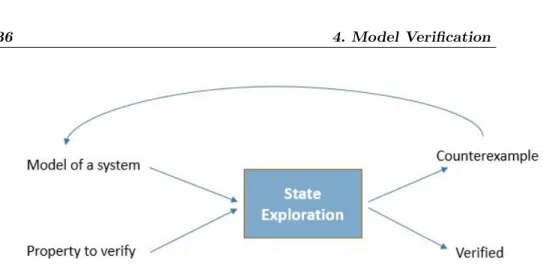
Model Checking [64] is a technique for verifying finite state systems

(FSMs). The advantage of this kind of systems is that verification

is completely automatic. The process uses an exhaustive search

of a given state space of a system to determine if a specification

is true or false. Given enough resources, the process will always

finish with a yes/no answer. In addition, it can be implemented

by algorithms with modest efficiency, which can be executed on

moderate-size machines (not on an average desktop computer).

Even if the restriction to FSMs may be a major disadvantage,

model checking is applied to various type of systems. Many

con-trollers are finite state systems, and many communication

pro-tocols. Sometimes, systems that are not finite are verified using

a combination of model checking and abstraction and induction

principles like our approach.

Applying model checking to a design consists of several tasks:

Modeling: Converting the design into a formalism (i.e:

transi-tion system) recognized by a model checker. In some case, having

limitations of resources (time and memory), the modeling design

may require an abstraction in order to remove irrelevant and

unim-portant details.

(50)

de-36

4. Model Verification

Figure 4.1 Model Checking process.

sign must satisfy before the verification. For CPSs, it is usual to

use temporal logic, which can define how the behavior of a system

evolves over time. The specification is very critical because it is

impossible to determine whether a given specification covers all

the properties that the CPS should satisfy.

Verification:

The verification is not fully an automatic task.

In practice, it evolves human assistance. The human expert must

analyze the verification results. In case of a ”No answer”, the

expert is provided by an error trace, called also a counterexample.

4.2

Model checking tools

Since developing a model checker is a complicated process and

since several model checkers already exist, it is easier to choose an

existing tool that is created and managed by experts in the model

checking field. In this section, we give a brief presentation of 4

model checking software : Spin[65], NuSMV[66], FDR2[67],

Alloy[68].

Spin: It was one the first model checker developed, starting in

1980.

It introduced the classical approach for on-the-fly LTL

model checking. Specifications are written in Promela [69] and

properties in LTL. An LTL property is compiled in a Promela

never claim, i.e. a B¨

uchi automaton. Spin generates the C source

(51)

4.3. Properties expression

37

code of an on-the-fly verifier. Once compiled, this verifier checks if

the property is satisfied by the model. Working on-the-fly means

that Spin avoids the construction of a global state transition graph.

However, it implies that transitions are (re-)computed for each

property to verify. Hence, if there are n properties to verify, a

transition is potentially computed n times, depending on

opti-mizations.

NuSMV: It is a model checker based on the SMV (Symbolic

Model Verifier) software, which was the first implementation of

the methodology called Symbolic Model Checking described in

[70]. This class of model checkers verifies temporal logic

prop-erties in finite state systems with “implicit” techniques. NuSMV

uses a symbolic representation of the specification in order to check

a model against a property. NuSMV is described later on details.

FDR2: It is an explicit state model checker for csp, the well

known process algebra. fdr2 can check refinement, deadlocks,

live-locks and determinacy of process expressions. It gradually builds

the state-transition graph, compressing it using state-space

reduc-tion techniques, while checking properties, which also makes it an

implicit state model checker.

Alloy : Alloy is a symbolic model checker. Its modeling language

is first-order logic with relations as the only type of terms. Basic

sets and relations are defined using “signatures”, a construct

sim-ilar to classes in object-oriented programming languages, which

supports inheritance. Alloy uses SAT-solvers to verify the

satisfi-ability of axioms defined in a model and to find counterexamples

for properties (theorems) which should follow from these axioms.

4.3

Properties expression

Temporal logics have been used to specify properties of

concur-rent systems since they were first proposed for this purpose around

1976, by Amir Pnueli [40]. Temporal logic is a particular variant of

modal logic, where new logical operators are introduced to

quan-tify over a family of objects in the system. In the case of temporal

Figura

Figure 1.1 Cyber-Physical Systems representation
Figure 1.2 V-model of MBD
Figure 1.3 Simulation-Based Verification Diagram
Figure 1.4 Formal Method-Based Verification Diagram
+7

Riferimenti

Documenti correlati

The positivity rate and the larval density per gram (number of larvae per g of examined tissue), both at muscle and visceral level, when present, were calculated;

Risk factors for graft survival after liver transplantation from donation after cardiac death donors: an analysis of OPTN/UNOS data.. Lee KW, Simpkins CE, Montgomery RA,

In order to quantify heat impact on ED activity during days with exposure above the threshold, we calculated the average and the max- imum daily number of high-priority

Rarely these disease are managed in the emergency setting, because are often diagnosed by urologists and the overall survival is about 34 months for the UTUC itself; the

Michele Barbato, Presidente Consiglio dell’Ordine degli Avvocati di Vallo della Lucania Avv.. Nunzio Luciano, Presidente

In this project, we attempt to extend this porting process to other vital parts of the QE code such as the Conjugate Gradient (CG) solver, Γ-point calcula- tions, etc., This

Since the publication of her seminal book Jurassic Management (1997) up to her recent works on School Academies, distributed leadership and the New Labour educational