ROBOTISED FAST CHARGING
OF ELECTRIC BUSES
S. TARAGLIO Energy Technologies Department
Robotics Laboratory Casaccia Research Centre, Rome
RT/2017/1/ENEA
ITALIAN NATIONAL AGENCY FOR NEW TECHNOLOGIES, ENERGY AND SUSTAINABLE ECONOMIC DEVELOPMENT
S. TARAGLIO Energy Technologies Department Robotics Laboratory Casaccia Research Centre, Rome
ROBOTISED FAST CHARGING
OF ELECTRIC BUSES
RT/2017/1/ENEA
ITALIAN NATIONAL AGENCY FOR NEW TECHNOLOGIES, ENERGY AND SUSTAINABLE ECONOMIC DEVELOPMENT
I rapporti tecnici sono scaricabili in formato pdf dal sito web ENEA alla pagina http://www.enea.it/it/produzione-scientifica/rapporti-tecnici
I contenuti tecnico-scientifici dei rapporti tecnici dell’ENEA rispecchiano l’opinione degli autori e non necessariamente quella dell’Agenzia
The technical and scientific contents of these reports express the opinion of the authors but not necessarily the opinion of ENEA.
ROBOTISED FAST CHARGING OF ELECTRIC BUSES S. Taraglio
Abstract
The robotic aspects of an automated charging system for electric buses is presented. The system is based on a plug mounted on a robotic arm visually servoed against a known marker towards the elec-tric socket. The system is described both in physical and software terms together with the needed optical calibrations. Results of operative tests are given.
Keywords: electric buses; fast charging buses; local transportation; robotic arm; visual servoing
Riassunto
In questo lavoro è presentato un sistema robotico per la ricarica automatica di autobus elettrici. Il si-stema si basa su una spina assicurata all’effettore di un braccio robotico che è visualmente guidato con l’ausilio di un marker conosciuto verso la presa elettrica. Il sistema è descritto sia in termini fisici che software insieme alle calibrazioni necessarie al suo corretto funzionamento. Sono brevemente in-dicati alcuni risultati di test operativi.
Parole chiave: bus elettrici; bus a ricarica veloce; trasporto locale; braccio robotico; servoguida visuale
Introduction
The physical system Software architecture
System calibration procedure Camera calibration Handeye calibration
Marker to socket calibration Experimental results and future work References 7 8 9 11 12 12 13 15 16
INDEX
7
Robotised fast charging of electric buses
Sergio Taraglio
Robotics Laboratory (DTE SEN IDRA), ENEA, C.R. Casaccia, Via Anguillarese 301, Rome, Italy
Abstract. The robotic aspects of an automated charging system for electric buses is presented.
The system is based on a plug mounted on a robotic arm visually servoed against a known marker towards the electric socket. The system is described both in physical and software terms together with the needed optical calibrations. Results of operative tests are given.
Introduction
Electric buses are going to be a viable solution in our ever increasingly congested and polluted towns and cities in the framework of a greener environment. There are two main classes of these vehicles: non-autonomous electric buses and non-autonomous ones. The first class comprises trolley buses or gap ones, the former gathering power from an overhead trolley from an aerial line, the latter from a ground level power supply, e.g. the Bordeaux tramway. Their flexibility is evidently limited, being directly linked to a power line [1]. On the other hand the autonomous electric buses store the needed power on board in high capacity batteries, offering the same flexibility of the fossil fuel powered ones and not needing important infrastructures such as a dedicated power line.
The onboard batteries obviously need recharging, but the recharge should be fast in order not to stop the bus too long, at least during working hours. Several hardware solutions have been studied and implemented by the various stakeholders, using pantographs of some kind, inductive charging or robotic arms as the hardware means of electrical fuelling, see e.g. [2][3][4]. In addition, different strategies can be applied: charging longer at the terminus of the line, charging on the fly at the bus stop or both, full recharge over night. Whatever the choice, the need for high currents, implying the use of unmanned devices for safety reasons, is mandatory.
In the following the robotic aspects of an automated charging system for an electric bus is presented. The system is composed of a robotic arm holding the plug, a camera viewing the environment and a managing software system able to drive the plug into the vehicle socket. Such a system should be deployed every few bus stops, or at the terminus, allowing a fast partial recharge of the bus batteries without human intervention. This work is part of a large national initiative funded by the Italian Ministry of Economic Development aiming at innovating the Italian national electric system, decreasing electric power costs for end-users;
8
enhancing the system’s reliability and the service quality, reducing the electric system impact on health and environment; allowing to use energy sources rationally and ensuring the country suitable conditions for a sustainable development [5]. Particularly a part of the initiative is directed to the aim of investigating several system aspects related to the intensive use of plug-in electric vehicles and their technical, environmental and economic impacts.
This work is the natural extension of an ongoing project studying the refitting of a public transportation vehicle, a Gulliver minibus by Tecnobus, for fast battery recharge in the context of urban mobility [6]. In the first section the physical system will be presented, in the second section the software architecture employed will be described. In the third section the needed calibrations to ensure correct geometrical transformations will be explained. Finally in the fourth section results and further developments of the system will be presented.
The physical system
The currents involved in the fast recharging of bus batteries are in the order of hundreds of amperes, this clearly indicates the opportunity to use robotic arms or similar fully unmanned devices. This solution is further sustained by the possible solution of quick recharges every few bus stops, implying a given number of charging stations, unreasonable to be fully manned.
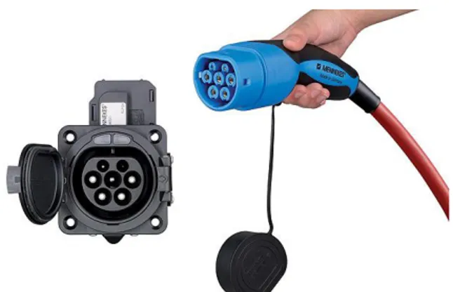
Figure 1. The UR10 robot by Universal Robots Figure 2. The Mennekes Type-2 plug and socket
The proposed system is based on a commercial robot arm, the UR10 model of Universal Robots [7], see Figure 1. The number 10 in the robot name stands for the allowed payload, i.e. up to 10 kg. This feature is important due to the actual weight of the plug and especially the relative cable used in the recharging process. In this proof of concept study, the employed plug is a Mennekes Type-2 [8], see Figure 2.
The plug has been designed for a human use, therefore some work has been done to make the robotic arm securely grasp the plug. In Figure 3 it is possible to see the additional white cylindrical structure mounted on the arm end effector, accommodating a camera and offering a hold for the three cable ties employed to fasten the plug. This experimental set up allows for some residual relative movement between the plug and the arm. This capacity of residual movement greatly helps the process of plugging, since there can often be a
9 negligible misalignment between the plug and the socket axes. It is important to remind here that the here presented system is a proof of concept, in the deployed system this feature will be implemented using a different solution: a dedicated support and a stiff rubber mounting.
On the above mentioned cylindrical structure it is housed a HD webcam (Logitech C615) securely fastened to the structure and thus to the arm.
Figure 3. The plug assembly with the camera
The system is completed by a laptop connected to the camera via a USB port and to the arm control box via an internet connection. It should be noted that a cable direct link is advisable in order to limit possible delays arising from other network traffic present in a more public network configuration.
Software architecture
The main aim of the system is to correctly insert the plug into the socket and refuel electricity in a fully autonomous and robust way. It is obvious that the bus, being driven by a human being, will place itself in a position sufficiently near to the robotic arm to fulfil the task, but not in a repeatable way. The system therefore should be able to measure the actual plug position and opportunely move the arm. The used means to this task is computer vision. A camera has been placed in a fixed position on the arm and a known marker has been placed on the bus next to the socket. The system recognises the marker and computes its three dimensional pose with respect to the camera. The camera pose with respect to the robotic arm origin can be known and thus the marker position with respect to the arm base can be found. The transform from the marker pose to the socket one can be measured and the overall position and pose of the socket with respect to the arm can be finally computed, allowing for the planning and subsequent motion of the arm.
All the system has been developed in the ROS framework (Robot Operating System). ROS is a middleware, i.e. “is a collection of software frameworks for robot software development, providing operating system-like functionality on a heterogeneous computer cluster. ROS provides standard operating system services such as hardware abstraction, low-level device control, implementation of commonly used functionality, message-passing between processes, and package management” [9].
10
The ROS architecture allows the building of a highly modular system, composed of several independent
nodes interacting one another via the publishing of or subscription to topics, i.e. data channels. Since ROS
has gained an outstanding place in the international community of robotic engineers and it is fully open source, it often happens that a needed node implementing a given task can be found already available on line. Naturally some customization work is always needed, but the effort can be limited with respect to a remarkable productivity.
In the presented system it has been exploited the ROS ViSP autotracker package, based on the work of the Lagadic group of INRIA [10][11]. This tracker employs a known pattern and estimates its position and orientation with respect to a calibrated camera. It requires the pattern 3D model and a configuration file. The algorithm first allows to detect automatically the marker using either a QR-code detector or a flashcode one, depending on the pattern used as marker. Then, from the location of the 4 marker corners, it computes an initial pose using a PnP algorithm (Perspective-n-Point: estimating the pose of a calibrated camera given a set of n 3D points in the world and their corresponding 2D projections in the image). This pose allows to initialize the model based tracker that is dedicated to track the two squares defining the black area around the QR-code. The tracker is also able to detect loss of tracking and recover from it entering in a new marker detection and localization stage [12]. In the left part of Figure 4 is shown the QR-code based marker used and in the right one a successful tracking example. Here it is possible to see the 3D reference frame as detected by the tracker (the tiny red, green and blue lines and the four light blue squares).
Figure 4. Left: the QR-code based marker; right: the marker as tracked by the tracking algorithm
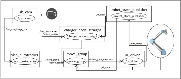
In Figure 5 is shown the software system architecture. It is composed of six ROS nodes: the camera controller, the video tracker, the arm controller and driver composed of three nodes and the main application governing the whole. In the figure are indicated also the ROS topics that the various nodes exchange, e.g. the robot_state_publisher node distributes the arm joint transforms (/tf_static) to the charger_node_straight (the main application) that needs to know the arm position and to the move_group node (responsible for the trajectory planning and control). The usb_cam node manages the video camera and the ur_driver one drives the robot.
11
Figure 5. The SW system architecture with ROS nodes (boxes) and exchanged topics (ovals and arrows)
At the beginning of a typical charging session the arm is in a rest position, while the tracker is up and running, processing the images incoming from the camera. As soon as the bus enters the camera field of view, i.e. when the tracker begins tracking the marker, the main application checks whether the marker is in motion or still. When motionless, it computes a trajectory which will take the plug in front of the socket but at a given distance (presently 30 cm) and actuates the arm to it, with the help of the move_group node. Then it re-acquires the marker position from this vantage point and computes the trajectory for the insertion. Finally it introduces the plug. This second view of the marker is used to confirm the first and to correct the target position if this is the case, being the second view far more reliable than the first out of its nearer and almost perpendicular position.
System calibration procedure
For the system to properly work, three different calibrations are needed: camera calibration, camera hand-eye calibration and marker to socket calibration.
Camera calibration is the process of estimating the intrinsic and extrinsic parameters of a pinhole camera model approximating the camera employed in a given task. Usually, the pinhole camera parameters are represented in two matrices called respectively the camera matrix, with the internal camera parameters, and the extrinsic matrix, carrying information on the camera three dimensional pose.
If a camera is mounted on a robot arm, it is necessary an additional step to know the relationship between the camera and the arm in terms of a roto-translational matrix, this is the so called hand-eye calibration.
Finally the marker to socket calibration is needed to compute the transform from the marker to the actual socket.
12
Camera calibration
A point in homogeneous coordinates in a world frame reference and the matching point on the image plane of a camera are related by a projective transformation matrix:
, (1) where s is a scale factor and P is a 3x4 projective matrix that can be decomposed into:
, (2) Here A is the 3x4 camera matrix describing the internal, or intrinsic, parameters of the camera:
, (3) with the optical centre of the camera (principal point), f its focal length, α and β take into account the pixel x and y physical dimensions and γ encodes the angle between the x and y axes of the CCD (skew), usually set at 0, being the two axes usually perpendicular.
The matrix is the so called extrinsic parameters matrix, relating the camera coordinate system with the world one, i.e. the camera position t and the rotation matrix R:
. (4) Besides perspective projection lens distortion must be also considered. This is usually modelled as two main contributions: radial distortion and tangential one; the first is due to defects in the lenses curvature, while the second is related to misalignments in the lens elements. The pixel distorted position in the CCD ( ) is linked to the undistorted one ( ) by the modelling relations:
(5)
where is the n-th radial distortion coefficient and is the n-th tangential distortion coefficient and r is the distance of the undistorted pixel from the principal point.
In the camera calibration process a given pattern of known geometrical characteristics is captured with the camera in several different positions. From a least square error minimization the correct values for both the intrinsic matrix and the distortion coefficients are computed, see for example [13].
Hand eye calibration
The hand-eye calibration problem is the computation of the relative position and orientation, or transform, between the robot arm gripper and a camera mounted on the gripper. The need for such a calibration is evident since any arm motion will be computed using the robot coordinates, while any information on the surrounding environment will come from the camera in camera coordinates.
13
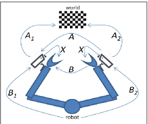
Figure 6. The hand-eye transformations at pose 1 and pose 2
The hand-eye calibration can be described in terms of homogeneous transformation matrices, [14]. With reference to Figure 6, let X be the transformation from camera to gripper (the unknown), the transformation from the camera to the world coordinate system and the transformation from the robot base to the gripper both at a given i-th arm position.
The camera-world transformation is obtained with the standard extrinsic calibration method, the robot-to-gripper transformation is directly given by the kinematics of the arm. For each pose of the robot arm there are two transformations as unknowns: robot-base-to-world and camera-to-gripper. But if two different poses are used (i.e. one motion from initial pose to final one) it is possible to eliminate the robot-base-to-world transformation and to write the equation:
(6) where and this equation can be developed into one matrix and one vector equations: , (7) (8) where R is the rotation ant t the translation, then it is possible to compute the rotation and translation estimation, usually the second after the first, but different authors use different strategies, see a survey in [15]. While actually performing hand-eye calibration, not only two positions and two images are considered, but several images of a not moving pattern are used at the same time, exploiting a larger number of views with an opportune optimization algorithm to reduce error.
Marker to socket calibration
This last step is the easiest one. Once that the above calibrations have been successfully performed, it is possible to know the marker pose with respect to the robot base. If the plug is manually inserted in the socket it is possible to directly read the socket position with respect to the robot base exploiting the arm kinematics. Thus the relative position and orientation between the marker and the socket position can be straightforwardly computed. In order to minimise the errors due to this last passage, the marker has been placed as near and as parallel as possible to the socket.
14
Figure 6. The RViz interface showing the arm with the camera (the black box over the end effector), the tracked marker position, the
consequent plug and in front positions.
In Figure 6 it is shown the ROS RViz interface where it can be seen the robotic arm, the marker pose, the plug pose and the second viewpoint in front of the socket as computed by the main application. The plug position is not on the same plane of the marker, due to the presence of the above mentioned additional cylinder, visible in Figure 3.
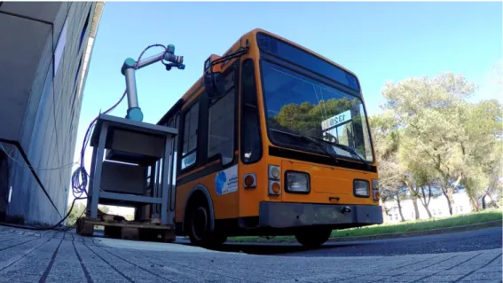
Figure 7. The experimental setup. The bus waiting for the arm to plug in,
15
Experimental results and future work
After some laboratory refinements on the marker to socket calibration, the arm has been moved outside to test it in operative conditions. The Gulliver electric minibus has been equipped with a box hosting both the socket and the marker on the right hand side of the bodywork. For an overall view of the experimental setup see Figure 7.
In Figure 8 is shown a detail of the plug aiming at the socket, visible below the marker. This snapshot is taken when the main application has already moved the arm in front of the socket and the second visual targeting is in progress. In the upper left the plug is successfully inserted in the socket.
Figure 8. The plug aimed at the socket. Upper left the plug inserted in the socket.
The system has been tested for twenty-two runs, where a single run means the starting of the bus well clear of the system, its stop beside the robot arm, the plugging and unplugging and the final exit. In 21 experiments out of 22 the system successfully plugged into the socket. In one case the plug hit the outer rim of the socket going into automatic safe stop. Of the 21 good tries, 5 needed bus repositioning. This means that the bus stopped in a position for which the arm could not plan a safe trajectory, i.e. a trajectory without self collisions of the arm with itself. The system has been designed to take this event into account and to take a corrective action, asking the driver to move further or back a little. The system appears to be quite robust under operative conditions, the main source of error being sometimes an incorrect segmentation of the marker when distant, plausibly due to illumination issues.
As above said this work is a proof of concept of automated re charging of electric buses, naturally further work can be foreseen. From the point of view of the visual servoing of the arm, future work will be aimed at the continuous acquisition of the target while plugging, differently from the present implementation where
16
the target is acquired only twice. Further work will be directed to the direct use of the socket as the visual marker to track. The socket posses a distinctive shape composed of seven holes contained in a larger chopped circumference, see Figure 2, that can be directly tracked, eliminating the need for the marker currently in use and avoiding one of the calibration steps. Another issue that will be considered is the design of a robotic arm customized for the charging application either with the project of an opportune gripper for the plug or the study of a different arm geometry especially conceived to avoid the self collision issues that sometimes force the driver to reposition the bus.
References
[1] https://en.wikipedia.org/wiki/Electric_bus last access 17 Nov 2016.
[2] https://twitter.com/TeslaMotors/status/629305813912326146, last access 17 Nov 2016.
[3] https://www.volkswagen-media-services.com/en/detailpage/-/detail/e-smartConnect-Volkswagen-is-
conducting-research-on-an-automated-quick-charging-system-for-the-next-generation-of-electric-vehicles/view/2448500/39073d24b0267de16d0888122a3ce16b?p_p_auth=m6PhR3iB, last access 17 Nov 2016.
[4] Corradini, M.G. “Ricarica veloce per autobus”, Automazione Oggi 393, Ottobre 2016.
and http://www.abb.com/cawp/seitp202/bc2c3a332d7a35c5c1257ee3002d9a19.aspx last access 17 Nov 2016.
[5] http://www.enea.it/en/research-development/electrical-system-research last access 17 Nov 2016.
[6] F. Baronti, R. Di Rienzo, R. Moras, R. Roncella, R. Saletti, G. Pede, F. Vellucci. Implementation of the fast charging concept for electric local public transport: the case-study of a minibus, Proceedings of INDIN
2015 IEEE International Conference on Industrial Informatics, 22-24 July 2015, Cambridge, UK
[7] https://www.universal-robots.com/ last access 17 Nov 2016. [8] http://www.mennekes.com/ last access 17 Nov 2016.
[9] https://en.wikipedia.org/wiki/Robot_Operating_System access 17 Nov 2016.
[10] A.I. Comport, E. Marchand, M. Pressigout, F. Chaumette. Real-time markerless tracking for augmented reality: the virtual visual servoing framework. IEEE Trans. on Visualization and Computer Graphics,
12(4):615-628, July 2006.
[11] E. Marchand, H. Uchiyama, F. Spindler. Pose estimation for augmented reality: a hands-on survey.
IEEE Trans. on Visualization and Computer Graphics, 22(12):2633-2651, 2016. [12] http://wiki.ros.org/visp_auto_tracker access 17 Nov 2016.
[13] Zhang, Z. “A flexible new technique for camera calibration”. IEEE Transactions on Pattern Analysis
17 [14] Danilidis, K. “Hand-eye calibration using dual quaternions”, The International Journal of Robotics
Research, 18(3): 286-298, 1999.
[15] Wang, C. Extrinsic calibration of a vision sensor mounted on a robot. IEEE Trans. Robot. Automat.
ENEA
Servizio Promozione e Comunicazione www.enea.it
Stampa: Laboratorio Tecnografico ENEA - C.R. Frascati gennaio 2017