Alma Mater Studiorum · Universit`
a di Bologna
SCUOLA DI SCIENZE
Corso di Laurea Magistrale in Informatica
GPU-BASED MANY-CORE
ARCHITECTURE EMULATION:
A DOUBLE LEVEL APPROACH
Tesi di Laurea in Sistemi Virtuali
Relatore:
Chiar.mo Prof.
Renzo Davoli
Correlatore:
Chiar.mo Prof.
Moreno Marzolla
Presentata da:
Andrea Monzali
Sessione II
Anno Accademico 2012/2013
“Con il simulatore di volo non si va in vacanza”
“Roooawh”
(Chewbacca)
Introduzione
Gi`a nel 1965 Gordon Moore (co-fondatore di Intel) teorizz`o che il crescente numero di transistor presenti in un microprocessore e la loro sempre pi`u pic-cola dimensione, avrebbero portato nei primi anni 2000 ad un’attenuazione nella crescita di tali dispositivi. Per andare incontro a questo fatto, la co-munit`a scientifica ha cominciato gi`a da diversi anni ad indagare il calcolo parallelo: se non `e pi`u possibile aumentare la potenza dei processori, `e pos-sibile introdurre pi`u unit`a di calcolo in un unico computer, delineando i due modelli di calcolo parallelo multi-core e many-core. Il primo `e attualmente disponibile nella maggior parte dei PC acquistabili nella grande distribuzione, tali architetture mettono a disposizione un numero di unit`a di calcolo normal-mente compreso tra 2 e 10. I processori della seconda categoria dispongono comunemente di centinaia o migliaia di unit`a di calcolo, sono normalmente adibiti ad usi specifici ed hanno costi decisamente pi`u proibitivi rispetto a quelli di un laptop.
Tuttavia, la mera duplicazione della capacit`a computazionale di un cal-colatore non `e sufficiente per aumentarne le prestazioni: architetture par-allele richiedono programmi paralleli e i vecchi programmi sequenziali non sono pi`u adatti per sfruttare le potenzialit`a offerte dai modelli multi-core e many-core, le applicazioni necessitano infatti di essere riscritte secondo ap-posti paradigmi di calcolo parallelo. Tali paradigmi vengono insegnati gi`a da tempo all’interno dei corsi di laurea di informatica e ingegneria informatica: gli studenti imparano i fondamenti della programmazione parallela e hanno la possibilit`a di testare quanto studiato sui libri attraverso i loro PC
ii INTRODUZIONE
giati di processori multi-core. La situazione cambia nel momento in cui viene approfondito il funzionamento di architetture complesse come ad esempio i processori many-core.
La presente tesi rientra in questo contesto: essa si pone l’obiettivo di fornire agli studenti uno strumento efficiente per realizzare e testare appli-cazioni parallele per architetture many-core. Per questo motivo `e stata inda-gata la tecnica dell’emulazione: essa consiste nella duplicazione delle funzion-alit`a di un sistema guest, al fine di renderle disponibili in un altro sistema, chiamato host. Cos`ı facendo il sistema guest pu`o essere testato utilizzando una sua versione software (un suo emulatore). Tuttavia, la realizzazione di un emulatore per architetture parallele many-core, consisterebbe in un con-siderevole numero di thread concorrenti, ciascuno dei quali emulerebbe una singola unit`a di calcolo; a prescindere dalla potenza di calcolo del sistema host, le prestazioni di un emulatore di questo tipo sarebbero troppo basse a causa dell’elevato numero di context switch tra i thread.
L’apporto di questa tesi consiste nel fornire supporto a questo tipo di elab-orazione tramite l’utilizzo delle schede video, le quali offrono una notevole ca-pacit`a computazionale normalmente adibita al rendering grafico. Parleremo infatti di processori grafici, o GPU (per Graphics Processing Unit ), che sono generalmente composti da alcune centinaia di unit`a di calcolo denominate core e che da alcuni anni sono di fatto programmabili e di conseguenza uti-lizzabili per la comune elaborazione e non pi`u esclusivamente per operazioni grafiche. Implementando all’interno di ciascun core della scheda grafica un thread, sarebbe possibile realizzare un emulatore per architetture many-core senza dover ricorrere ad hardware aggiuntivo (le GPU sono normalmente incluse nella maggior parte degli odierni PC o laptop).
Il problema `e che le GPU offrono una grande potenza di calcolo at-traverso processori SIMD (Single Instruction, Multiple Data), i quali es-eguono la stessa istruzione in maniera sincrona utilizzando dati differenti; ci`o pone un limite non da poco visto che l’applicazione parallela eseguita dall’emulatore potebbe prevedere flussi di esecuzione differenti. Per ovviare
INTRODUZIONE iii
a questo problema una nuova tecnica di emulazione `e stata introdotta: essa descrive l’esecuzione di un algoritmo in termini di dati, i quali vengono rice-vuti in input da un singolo programma che “adatta” la sua esecuzione in base al dato (all’algoritmo) ricevuto. Tuttavia il programma `e sempre uguale, il che lo rende adatto ad essere eseguito sui core di una GPU.
`
E bene precisare che le librerie per la programmazione di GPU organiz-zano l’esecuzione dei thread sui core in modo da minimizzare la divergenza (ovvvero il tentativo da parte di pi`u processi di eseguire differenti istruzioni all’interno dello stesso ciclo di clock); per questo motivo l’approccio clas-sico di emulazione `e stato implementato per essere confrontato con quello nuovo da noi sviluppato, al fine di delineare la possibilit`a e le modalit`a di un possibile approccio ibrido.
Contents
Introduzione i
I
State of the Art
1
1 Aims of this Thesis 3
2 Virtual Machines & Emulation 7
2.1 Emulation vs Simulation . . . 8
2.2 Full system and User mode emulation . . . 10
2.3 Available Virtual Machines and Emulators . . . 11
3 General Purpose Computing on GPU 15 3.1 The Graphics Hardware . . . 15
3.2 The GPGPU . . . 17
3.2.1 An overview: when, what, why and how . . . 17
3.2.2 Branches and Divergence . . . 19
3.3 Available Tools . . . 21
3.3.1 Brook . . . 21
3.3.2 CUDA and OpenCL . . . 22
II
A double level approach for Emulation
29
4 The Emulated Architecture 31 4.1 The Integer Java Virtual Machine . . . 34vi CONTENTS
4.1.1 Registers . . . 36
4.1.2 The memory structure . . . 36
4.2 The emulation of the IJVM model . . . 38
4.2.1 Evaluation . . . 40
5 ISA level emulation 43 5.1 The Fetch-Decode-Execute cycle . . . 43
5.2 A parallel architecture emulator . . . 44
5.2.1 Improvements for the ISA emulation . . . 45
6 Micro Architecture level emulation 47 6.1 The execution model . . . 48
6.1.1 The micro-instruction . . . 50
6.1.2 The ALU . . . 51
6.1.3 The memory model . . . 52
6.1.4 The execution path . . . 54
6.1.5 An example . . . 54
6.2 Improved models . . . 56
6.3 The MIC model . . . 61
6.3.1 A branch-free code . . . 62
6.3.2 An exactly mapping . . . 65
6.4 The PMIC model . . . 67
6.4.1 A parallel architecture . . . 67
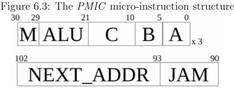
6.4.2 A new micro-instruction structure . . . 70
6.4.3 A language for PMIC microcode . . . 71
7 Conclusions and Future Works 77 7.1 GPU execution time . . . 80
7.2 Memory usage . . . 81
7.3 Future Works . . . 82
List of Figures
3.1 A schematic vision of the RV710 GPU architecture, taken
from [3] . . . 17
3.2 The OpenCL execution model, taken from [28] . . . 24
3.3 A 2D Work-Group example, taken from [28] . . . 26
3.4 The OpenCL memory model, taken from [28] . . . 27
4.1 The multilevel structure of Computer defined in [14] . . . 33
4.2 The memory model . . . 38
6.1 The Mic-1 execution Path, taken from [14] . . . 49
6.2 The Micro-instruction structure, taken from [14] . . . 50
6.3 The PMIC micro-instruction structure . . . 71
7.1 Execution Time . . . 79
7.2 Execution Time . . . 80
7.3 Time per Instruction . . . 81
7.4 Memory Usage . . . 82
List of Tables
3.1 GPGPU programming nomenclature . . . 23
Part I
State of the Art
Chapter 1
Aims of this Thesis
Microprocessors based on a single processing unit dominated the market for more than two decades, increasing their clock frequency and reducing their die area [2]; this trend reached its limit around 2003 due to the high power consumption and the heat dissipation. Hence, processor manufacturers begin to switch their designs to models with more than a single computation unit (core), leading to the multi-core and the many-core architectures [12]. These two models differ in the number of cores, between two and ten for the former and several hundreds for the latter.
As the computational architecture moves from a single-core to a multiple-core model, sequential programs are no longer able to exploit the performance offered by processors. Indeed, they have to be explicitly rewritten in a multi threaded fashion and this require new specific programming paradigms.
Nowadays, common off-the-shelf PCs and laptops expose multi-core pro-cessors, making them an adequate testbed for parallel application developing (with the aid of high level libraries such as OpenMP [13] and MPI [15]). How-ever, this is not true when considering the many-core architecture: writing applications specific for this kind of processor forces you to use hardware with high costs and that is usually not available in common markets. To overcome these limitations two different concepts are introduced:
Emulation Given a guest system SG and a host system SH, the emulation
4 1. Aims of this Thesis
consists in the implementation of the SG functionalities on SH. Using this approach, a parallel many-core architecture can be emulated us-ing a laptop and parallel many-core applications can be executed (i.e., their execution can be emulated) on the laptop multi-core processor. However, this approach presents very low performances, due to the many-to-multi core mapping and the resulting high number of context switches.
Graphic Cards Graphics Devices (even those present in commodity PCs or laptops) are real many-core processing units, normally targeted to ren-dering, shading and texturing. They provide a big instruction through-put and a very high memory bandwidth. Thus, the Graphics Hardware is considered Graphics Processing Units (a.k.a. GPU). Starting from the early 2000s, GPUs have became programmable [2], allowing gen-eral purpose applications to be written using a high level language and executed on the top of a GPU.
These two concepts lead to the develop of a GPU-based many-core archi-tecture emulator, such that real many-core applications can be written, tested and debugged on the emulator, while the required computational power is offloaded to the GPU cores. However, the graphics hardware does not direct support the execution of different flows. According to the Flynn taxonomy [22], the most suitable parallel model for our purpose should be the MIMD one (for Multiple Instruction, Multiple Data), this model allows multiple ex-ecution flows to be executed on different cores, working on different memory portions.
GPUs are many-core platforms that typically expose a Single Instruction, Multiple Data-like paradigm (SIMD ), hundreds of cores are organized into several groups, each of which has a specific roles in the rendering pipeline. Cores from different groups are autonomous, but inside the same group they expose a SIMD behavior, where a single control unit fetches and broad-casts the same instruction to all processing elements [1], forcing them to
5
execute the same operation (Single Instruction) using different memory por-tions (Multiple Data).
GPU programming environment (like CUDA [21] and OpenCL [20]) usu-ally implement a Single Program, Multiple Data (SPMD ) programming paradigm, that is a paradigm for MIMD architectures. Each core runs an instance of the same program, using its own Program Counter following a specific path through the program [18].
The mapping from the SPMD paradigm exposed by GPU programming environments and the SIMD -like architecture exposed by GPU hardware is not trivial and it is not fully manageable by the programmer. Hence, some kind of task parallelism can fit GPUs, but some others cannot.
To investigate this topic, the classical emulation approach is compared with a new one. Typically, emulators work at the Instruction Set Architecture (ISA) level, providing a routine for each ISA instruction that is on-demand invoked every time the emulated processor fetches the corresponding opcode. Implementing such an emulator in each GPU core would cause different cores to emulate different execution paths, leading to the divergence phenomena (i.e., different instructions that should be executed in parallel during the same temporal step, are sequentially performed).
The new approach here proposed tries to answer the question “is it possi-ble to express different computation using different data, handled by a unique algorithm?”
At a first sight, the answer could be a clearly “yes”, the λ-calculus it-self is a mathematical formalism for express computation where there is no distinction between programs and data.
But how this concept can be (efficiently) translate in practice? This thesis describes the emulation of a simple processor, where instructions are coded in terms of data that will be handled by a unique program. This approach become particularly interesting when considering GPUs as the host platform for the emulation. Now, each core can execute the same program, discarding all divergence issues.
6 1. Aims of this Thesis
For this purpose, processors are investigated at the Micro Architecture level, just a step above the rough hardware. Here, the hardware always performs the same execution path and different bits (the data) tune that execution to express different instructions behaviors.
Clearly, this approach has a cost: simple instructions that previously would have been emulated by few lines of code, now require one or more cycles that are executed by a software, and not directly by hardware. This thesis takes the classic approach (that is not well suitable for GPUs) and the new one (that has a high computational cost) and compares them, looking into the chance (and corresponding modalities) for a hybrid solution.
Chapter 2
Virtual Machines & Emulation
The majority of the computer science related topics are not concrete, the software is not a physical entity, but a virtual concept. However, within the computer science world the term virtual receives a specific meaning that express the ability to play the same role of another entity, offering the same interface to the outside world [16].
In computer science there are two main concepts: the abstraction and the interface, the former defines the operations an entity can perform, while the latter is the way by which these operations can be requested. For example, a software library defines new operations abstracting from the underlying levels (whether hardware or software) and it defines an API through which other entities can invoke the defined operations. The virtualization technique provides software entities that expose the same interface of another system, such that they can substitute it in every context.
This thesis investigates the virtualization concept through the emulation technique. Despite these two concepts are slightly different, they share the ability to implement a target system functionalities on a different one. The Virtual Square taxonomy [16] categorizes virtual machines according to their consistency to the lower layer interface. Virtual machines can be either ho-mogeneous or heterogeneous depending on whether or not they provide the same interface of the system where they run. Processor virtualizers can
8 2. Virtual Machines & Emulation
cur in both modalities, on one hand homogeneous virtual machines allow the creation of a virtual environment with the same features of the system where the VM runs. On the other hand, a heterogeneous virtual processor permits a program compiled for a different architecture to be executed on the host system. Emulators are included in this latter category.
The emulation is a computer technique that duplicates the functionalities of a computer system (the guest ) in another system (the host ), this allows the host system to behave as a real instance of the guest system.
Let X be an either hardware of software entity, the entity E(X) (that can be either hardware or software too) is said to be an emulator of X if it allows another entity Y to be interfaced to E(X) as it would be interfaced to X.
Thus, a processor emulator allows to take a program compiled for an arbitrary architecture (e.g., i386, arm, mips, ppc, etc) and to observe its execution on the emulated processor, running on a different platform.
A video game console emulator is a program that run on either a computer or a video game console, it allows the execution of some games that were originally designed for a different console. For example, an emulator for a legacy video game console permits to use games for which the dedicate hardware is no longer sold.
“Emulation” is a black box term, that can be addressed by multiple points of view, this thesis focuses on the processor emulation, in particular on the many-core processor emulation. This kind of architecture exposes a high number (i.e., several hundreds) of processing elements, that differs from the multi-core architecture that nowadays offers between two and ten computa-tional units, [2]. Following sections will explain some key concepts of the emulation technique.
2.1
Emulation vs Simulation
As a first step, it is important to distinguish between these two terms, that concern techniques with similar aims but with different effects.
2.1 Emulation vs Simulation 9
The emulation technique allows the creation of entities that implement all functionalities of a guest (i.e., emulated) system. Emulators expose the same interface of the guest, so that other entities can interact with them in an unmodified manner.
On the other hand, the simulation technique produces environments that mimics the simulated system behavior. Hence, simulators expose interfaces that are different from the one exposed by real instances of the guest (simu-lated) system. Entities that can be interfaced with a specific system have to be rewritten when interfaced with a simulator of that system.
Consider for example a network simulator where packets are exchanged between simulated nodes occurring in some delays that are (hopefully) similar to real world network delays. In such a context, new protocols can be tested, observing how applications behave. But a network simulator is an unreal environment where nodes are not real ethernet-linked nodes, no packet is really exchanged and all delays are generated by the simulator. Real network applications cannot run on (i.e., they are not able to be interfaced with) the simulator. On the other hand, a network emulator forces applications to open sockets, to sends and to receive data packets as they would normally do [16].
Thus, the difference between emulation and simulation lies in the inter-face: while the simulation just mimics the target system behavior (it defines new interfaces, it requires new application), the emulation maintains inter-faces unchanged, so that real unmodified applications can interact with the emulated system.
These two techniques have different use-cases, both of them present ben-efits and drawbacks and sometimes they compare coupled in a hybrid form. However, the emulation presents two main benefits:
applications written (and tested) on the emulator can be executed on a real instance of the target processor, and vice versa (applications written for the target system can be tested using the emulator)
10 2. Virtual Machines & Emulation
can be developed) without really owning it
The latter point has a great importance in the education field, where students study from the books how to use specific hardware platforms but they cannot test them due to their high cost or their unavailability. In par-ticular, this thesis deals with many-core processor emulation, giving students the chance to develop an application suited for a 100+ cores processor, using their own PCs or laptops.
2.2
Full system and User mode emulation
As said before, the term “Emulation” is a special case of the more general concept of virtuality, or virtual entity [16].
An entity XV is a virtualization of X if it can efficiently replace (i.e., it
can be used instead of) X itself. In this sense, emulation could be treated as a form of virtualization, it creates a virtual version of a either hardware or software component and this virtual component can be used instead of the real one (other entities can interact with it as they would do with the real one).
Thus, the term “emulation” no longer refers to a rigid hardware-by-software implementation, but whatever entity can be virtualized, in order to create its virtual version, that can replace the real one in every context. The expression “whatever entity” means that each system (from a small chip to a big and complex computer architecture) can be replicated by software via emulation/virtualization. This leads to multiple emulation approaches, depending on the complexity of the emulated system.
Firstly, a full system emulation duplicates the functionalities of a com-plete computer architecture, including instruction execution, memory man-agement, I/O devices, etc. This mode permits to run a complete O.S. stack, testing all its functionalities.
Clearly, a full system emulator requires a considerable coding effort that sometimes could be useless: most of the emulated components could be
al-2.3 Available Virtual Machines and Emulators 11
ready available in the host system. This leads to another approach, where only some parts of a complex system are emulated and coupled with the rest of the host system, which occurs in its real (not emulated) version.
This second modality includes the user mode emulation approach, which takes into account only the processor virtualization, discarding all other hard-ware components with which it is connected to. Hence, an unmodified pro-gram compiled for the target architecture can be “executed” on (i.e., its execution can be emulated by) a virtual processor.
Qemu is an example of a software that allows both presented modalities (see the next section for more details).
Pushing forward the concept of partial emulation (where only specific components are emulated), it is possible to emulate just a small part of a big entity. This thesis, for example, emulates only the execution path of the Java Virtual Machine. As discussed in chapter 1, the main goal of this work is the development of an emulator that can execute multiple execution flows in parallel, running on GPUs.
For this reason, the execution path will be the only focus of this thesis and components like interrupts handler and memory management unit are discarded. Furthermore, the choice of the target processor is not crucial (as discussed in chapter 4), the implemented ISA is a subset of Java Bytecode, that is much less powerful then the real Java language (no object oriented expressiveness, no input/output and integer only operations).
2.3
Available Virtual Machines and
Emula-tors
As said in the beginning of the chapter, virtual machines and emulators are similar concept but they do not coincide; not all emulators are also virtual machines and vice versa. To clarify the differences between these two con-cepts, both virtual machines and emulators will be presented, highlighting the membership of each tools.
12 2. Virtual Machines & Emulation
Qemu Qemu (short for Quick EMUlator, [17]) is a software that can be considered both an emulator and a virtual machine; it currently emu-lates different architectures such as i386, arm, mips and ppc. It allows the complete emulation of the target system in order to execute an unmodified O.S. in a virtual environment.
To achieve high performances, it implements a technique called dy-namic binary translation, the first time a target instruction is reached Qemu translates it to a host system code fragment and stores it, so that it can be reused the next time the emulator reaches that instruction. Due to its performance, Qemu can be used as a virtual machine instead of the real architecture in order to test, debug and run Operating Sys-tems; moreover, it allows (only under Linux) the execution of programs compiled for a different architecture without having to start a complete OS stack (User mode Emulation).
According to the Virtual Square taxonomy [16] it can be considered a Heterogeneous virtual machine, since it expose to programs a different interface from the one exposed by the host system,
KVM, Virtual Box These two tools are virtual machines, but they are not emulators. Indeed they allow the complete virtualization of an architecture but they force the guest and the host systems to be the same. They are Homogeneous virtual machines.
To achieve near native performances, these tools make use of hardware-assisted virtualization, that permits a direct and fast instruction map-ping from the target to the host (that clearly force these two architec-ture to be the same).
Java Virtual Machine As the name suggests, the JVM is a virtual ma-chine that allows the Java Bytecode to be executed on an arbitrary architecture. However it is not considered an emulator in the strict sense; the guest system (the emulated one) is just an abstract specifi-cation and it does not appear in any real implementation, thus the JVM
2.3 Available Virtual Machines and Emulators 13
is not considered an emulator since it implements the functionalities of a non-existing entity.
uMPS Finally, this is the case of an emulator that is not a virtual machine. µMPS is an educational computer architecture emulator developed at the University of Bologna, that implements the MIPS I Instruction Set [29]. Due to its educational goal it cannot be considered a virtual machine since it is not a good substitute for the real MIPS processor. It allows students to design an Operating System from scratch on the top of a simple hardware, controlling its execution step-by-step. However, using it in a real context implies unacceptable performances because the emulator goal is the correct execution of a program and not the time require for this execution.
Chapter 3
General Purpose Computing on
GPU
The Graphic Processor (sometimes called Graphics Processing Unit, or GPU ) is the engine element of the Graphic Hardware, the computer device responsible for the graphics elements management. Nowadays, GPUs are included in most of the off-the-shelf PCs or laptops, providing a dedicated hardware for the rendering process. To achieve high performances, this pro-cess makes use of several hardware components, each of which exposes a huge number of synchronous Processing Elements (PEs).
GPUs currently represent one of the most powerful computational hard-ware per dollar, moreover they expose a high memory bandwidth, making them an interesting device for non-graphic tasks too, through the processing elements exploitation, in order to achieve General-Purpose computation [4].
3.1
The Graphics Hardware
Graphics devices are today included in all commodity PCs, their task is the creation of a 2D image (i.e., a two dimensional array of pixel) starting from a scene description, provided in terms of an either 2D or 3D geometry, color, light and texture informations, [23, 24].
16 3. General Purpose Computing on GPU
To achieve high performances, all GPUs manufacturers design their de-vices according to a well defined structure call Graphics Pipeline (or Render-ing Pipeline). This pipeline includes five stages, each of which has a role in the rendering process that is performed by a dedicated hardware component. These steps are:
Vertex Operations Primitive Assembly Rasterization
Fragment Operations Texturing
Due to the parallel nature of the problem, Rendering Pipeline steps are usually executed by several Single Instruction Multiple Data (SIMD ) pro-cessing elements working in parallel on multiple memory portions.
For example, Figure 3.1 shows the Radeon RV710 structure [3] (the testbed GPU for this thesis); it exposes 4 Rasterizers, 16 Fragment Pro-cessor and 8 Texture Units. Although the RV170 architecture is a low-end solution (it contains few processing elements), it is able to provide a big amounts of computational power.
In the following sections we will give an overview of the GPGPU concept, specifying capabilities and use-cases. As a preamble, it is important to note that one of its main aims is the ability to provide a high computational power without forcing developers to know low-level hardware details (though a minimal knowledge of the device behavior is clearly required). For this reason this thesis will not deal with the Graphics Pipeline process, leaving interested readers to [5].
3.2 The GPGPU 17
Figure 3.1: A schematic vision of the RV710 GPU architecture, taken from [3]
3.2
The GPGPU
The General Purpose Computation on Graphics Processing Units, from now GPGPU, is the exploitation of the Graphic Hardware (that is usually used for pixel management) for non-graphics tasks [6], this is a non trivial goal due to the Special-Purpose nature of this kind of devices. The next parts of this section discusses some GPGPU aspects.
3.2.1
An overview: when, what, why and how
In 1999 the NVIDIA company released the first programmable Graphics card: it can be consider the GPGPU birth. Before this date all rendering stages were hardwired; starting from the Vertex and the Fragment stages, all pipeline components were gradually transformed from fixed-function stages to developer-manageable programs. This capability, coupled with the in-troduction of an assembly language for stages programming, had enabled the General-Purpose Computation for Graphics Hardware, or GPGPU, term coined in the early 2000 by the NVIDIA itself. In 2002 another important result was achieved by the ATI Radeon company (now AMD ) which has
18 3. General Purpose Computing on GPU
introduced the floating point computation inside the Fragments Operators. Beside these important results, a GPGPU community raised during these years [25], developing interesting solutions for the developers, some of which are described in the following sections.
Graphics devices offer some interesting features like big computational power, high memory bandwidth and a quick performance growth; despite this they are Special-Purpose devices. Thus, using them for General-Purpose computations presents some challenges. Firstly, the high computation power is offered through several Single Instruction Multiple Data (SIMD ) elements, where a single control unit fetches and broadcasts the same instruction to multiple processing elements [1], that are forced to synchronously execute the same instruction using different memory portions.
While writing software for a single-core CPU is relative sample, the ex-ploitation of a parallel architecture requires to write explicit parallel code; and since GPU processing elements are organized in a SIMD -like fashion, par-allel code must be tuned for a SIMD architecture. Due to this fact GPGPU is recommended for computing intensive tasks while interactive programs are not well suitable for Graphics Hardware.
Moreover, GPUs provide high memory bandwidth for inner operations, like load and store, but the exchange of data between the Main Memory (the CPU) and the device memory is very expensive; so interactive programs are still not suitable for Graphic Hardware.
Fortunately, not all programs require an interaction with a human user or with some other device, there is a big class of GPU-suitable tasks like mathematical and physical computation (FFT [7], Matrix Multiplication) or graphics tasks itself (like Ray Tracing).
Beside these specific classes of tasks, there is another trend in the GPGPU that aims to treat the GPUs power in an even more general an flexible way, using it for any kind of computation, like it is a real coprocessor. Within this approach, it is possible to operate at different levels: [10] and [9] are ex-ample of GPU exploiting at the O.S. level, where GPU processing elements
3.2 The GPGPU 19
are treated as any other O.S. managed resource over which processes can be scheduled. On the other hand, [8] and [11] use GPU computation power to speedup the virtualization and the simulation techniques, so that unmodi-fied programs (compiled for a specific target platform) can be executed in a different context. This field has a special impact in this thesis, whose goal is the design of a many-core architecture emulator; however this is not a trivial task (as pointed out in [11]) due the SIMD-like architecture of the Graphics devices; this issue will be addressed in the second part of this thesis.
In recent years, GPGPU development tools have evolved providing high level solutions for GPU parallel applications developing; today these tools usually include a compiler from a C-like syntax to the GPU assembly lan-guage. Such assembly languages have evolved too, thus Graphics Instruction Sets does not only allow geometric primitives management, but some clas-sical operations like mathematical, bitwise, memory and jump instructions are now included (memory and jumps operations will be deeper discussed in following sections).
3.2.2
Branches and Divergence
There is an important issues to address while studying GPGPU : since processing elements are clustered in a SIMD fashion, they are forced to syn-chronously execute the same instructions stream; but what happen if several Processing Elements evaluate the branch condition of an if -like statement to different boolean values? Conditional jump instructions have a key role in an assembly language since they are mandatory for loops description, in a full-fledged programming language conditions and loops must be available, otherwise the language capabilities would be very limited.
This issue can be addressed in several ways, the first one takes into ac-count the GPU architectural design [23], branching can be direct imple-mented in hardware according to three modalities:
Predication This is not a strictly data-dependent branching, when the ex-ecution reaches a branch, both paths are evaluated and then, within
20 3. General Purpose Computing on GPU
each PE, one path is discarded according to the boolean branch con-dition. It is the simplest method for branching support in GPUs and thus it exposes very low performances.
MIMD branching The Multiple Instructions, Multiple Data (MIMD ) ex-ecution model would be the ideal hardware for branching support since each processing element is autonomous during the execution (i.e., it has a dedicated fetch/decode unit). To achieve this result, MIMD branch-ing usually requires additional hardware components, that make the GPUs design more complicated. Apart from some NVIDIA cards, the MIMD branching support is not included in the majority of the GPUs [23].
SIMD branching This is the most widely adopted model: processing ele-ments are organized in SIMD groups and when the execution encoun-ters a branch instruction all boolean conditions are evaluated; if all these values are identical only one path will be executed. On the other hand, if one or more values differ from the others, both paths are exe-cuted and then each PE discards the result of the undesired path. (as in the Predication model)
The execution of both branch paths, discarding one of them according to the branch condition flag implies a great performance downgrade since a lot of cycles are wasted for a useless computation. The extreme case consists in multiple synchronously Processing Elements (PEs), each of which attempts to execute its own path; the available parallel power will be lost since all PEs would execute all possible branches, leading to a sequential-like execution. This phenomena is called divergence.
In addition to these, there are some further techniques to address the branching issue, which work at a higher level [26]; they try to establish if a branch path is useful or not, so its execution could be discarded in advance. This could be done either statically (with some Branch resolvers) or during the execution.
3.3 Available Tools 21
3.3
Available Tools
Any successful programming framework requires at least three additional components: a high level language, a debugger and a profiler [23]. Though profilers are very hardware specific (and their number is very limited), a lot of high level languages and debuggers are today available for GPU program-ming; this section focuses on popular languages, they can be organized in two main categories, Shading languages and General Purpose languages.
Languages from the first group share the common idea that the GPU main aim is the pictures creation, thus all the computation must be expressed in terms of graphics objects management. Languages belonging to this cate-gory are Cg (for C for Graphics, developed by NVIDIA), HLSL (for High Level Shading Language, a proprietary Microsoft language) and GLSL (for OpenGL Shading Language, from the OpenGL Architecture Review Board consortium).
Although it is quite simple to map these languages to a Graphics pro-cessor, they force developers to think a parallel application in terms of ge-ometric primitives, vertices, fragments and textures, while General-Purpose algorithms are well described as memory and mathematical operators, that are concept much more familiar to classical CPU programmers.
For this reason, a second category of programming languages has been developed, in order to allow programmers to write GPGPU applications in a more familiar environment.
3.3.1
Brook
The Brook programming language is an ANSI C extension, developed at the Stanford University [27]. It allows applications to be designed in terms of streams, that are similar to arrays except from the fact that streams components can be accessed in parallel by a kernel.
A kernel is a routine that runs on the Graphics processor; due to the parallel nature of the GPU, multiple kernel instances will be executed using
22 3. General Purpose Computing on GPU
the stream components as input.
In a Brook source, a kernel is a function, within its arguments it is possible to specify several input streams and one output stream. The source is pre-compiled by the brcc compiler, which transforms it in a C++ file, that can be in turn compiled using the standard GNU C Compiler tools. Within the so generated C++ file, the kernel function is transformed into a target specific assembly code that can be executed on various platform, including GPU and CPU itself.
3.3.2
CUDA and OpenCL
After Brook emerged, many similar solutions were born, in 2006 NVIDIA released the first Computing Unified Device Architecture (CUDA) SDK, a programming environment for parallel application developing. CUDA has quickly became the standard de-facto for NVIDIA GPUs programming.
In 2008, some industries defined the Open Computing Language (OpenCL) standard, that try to mimic the CUDA environment using a different aim: while CUDA works only with NVIDIA GPUs, OpenCL is a Heterogeneous Computing standard, it assumes multiple devices to be used for generic com-putations. Today, a lot of micro-processor manufactures provide a OpenCL implementation for their hardware. Despite the difference in the initial aim, these two programming tools are very similar, that is the reason why they are treated together. They expose a very similar programming and memory model, both described below.
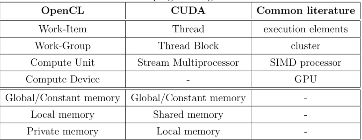
OpenCL was developed in order to design a more flexible version of the CUDA environment, that does not force developers to use an NVIDIA device, but it allows the usage of any processing devices (like, for example, GPU, CPU and DSP). There is a strict correspondence between these two program-ming tools that allows to use terms from the two contexts interchangeably. Table 3.1 correlates terms from these two programming environments, more-over it shows a further column that contains other terms frequently used in literature for address the same concept.
3.3 Available Tools 23
Table 3.1: GPGPU programming nomenclature
OpenCL CUDA Common literature Work-Item Thread execution elements Work-Group Thread Block cluster Compute Unit Stream Multiprocessor SIMD processor Compute Device - GPU Global/Constant memory Global/Constant memory
-Local memory Shared memory -Private memory Local memory
-Finally, it is important to claim that even if they inherit the majority of the design from the Brook language, they cannot be considered streaming languages. On the contrary, both CUDA and OpenCL support the Single Program Multiple Data (SPMD ) paradigm, where multiple processing ele-ments execute different portions of a unique program, the kernel.
The programming model
The design of a GPGPU parallel application requires two parts: a host and a kernel, the former is a classical sequential application that runs on a common CPU with an Operating System like Linux, Windows or MacOS. A kernel is a routine that runs on the Graphic Processor, exploiting the device high parallelism.
One of the host job is the creation of the environment for the kernel launch, it consists in several phases:
(i) the establishment of the target device for the computation (there could be many devices in a system and the CPU itself could be used as a target device)
(ii) the compilation of the kernel code
24 3. General Purpose Computing on GPU
(iv) the choice of how many execution elements has to be parallel executed After that, the parallel phase could start, at the end of which, the host application could copy back the results from the GPU buffers to the Main Memory.
To abstract from the different GPU architectures, kernel programmers could assume that the underlying hardware is organized according to a well-defined hierarchy; since each GPGPU library uses its own names to de-note the same set of concepts, terms from the same line of Table 3.1 will be used in this thesis interchangeably, however since the main focus is on the OpenCL programming environment, terms from this framework will be mainly adopted.
The Figure 3.2 depicts the developer point of view, here the host ap-plication can interact with several Compute Devices, each of which consists of multiple Compute Units (CUs), within a CU the computation occurs through Processing Elements (PEs) that are clustered in some groups.
Figure 3.2: The OpenCL execution model, taken from [28]
A work-item (WI ) is the software entity that logically correspond to an execution flow, the OpenCL runtime system maps each WI to a PE during the kernel execution and all WIs run the same code.
According to the input data, a kernel can organize its WIs in an N dimensional structure, with N ∈ {1, 2, 3}; WIs are clustered in group, called
3.3 Available Tools 25
work-groups (WG ), each of which must contain the same number of WIs. OpenCL specification ensures that all WIs within a WG run in parallel on the same CU.
Once the kernel has been compiled, it must receive both the global num-ber of WIs to execute and the size of a WG, the numnum-ber of groups can be retrieved dividing these two values. Clearly, the WG size must divide the global number of WIs. As example, the Figure 3.3 shows a two dimensional kernel structure with Gx × Gy WIs clustered in groups with size Sx × Sy.
Each work-item can retrieve its position within both the work-group and the whole structure though the built-in functions
int get_local_id(int dimension); int get_global_id(int dimension);
Both functions have an integer parameter that indicates the dimension over which the position must be retrieved. Figure 3.3 assumes that the num-bering starts from the top left of the grid, counting from zero; the WG with index (1, 1) is zoomed showing all WIs inside of it. Within a WI there are the sx and sy variables that hold the WI indices inside the WG (local
in-dices). These indices could be retrieved using the first of the above functions (get local id ), with arguments 0 and 1 respectively.
Once the kernel has launched, this model is mapped to the device archi-tecture; this mapping could be more or less efficient depending of the device capabilities; since all WIs within a WG runs in parallel on the same CU, the maximum number of WI in a group is limited by the physical number of processing elements of a CU (regardless of the number of dimension). If an application requirement (i.e., the number of WIs to be parallel executed) is bigger then a CU capacity, multiple WG must be defined. It is possible to concurrently execute as many WGs as the number of the device CUs; work-items can coordinate themselves only within a work-group, thus if a device is equipped with multiple CUs, several WGs can be concurrently executed but WIs from different groups are not able to synchronize them.
26 3. General Purpose Computing on GPU
Figure 3.3: A 2D Work-Group example, taken from [28]
The memory model
GPUs usually expose a high memory bandwidth such that various Pro-cessing Elements (vertices, fragments, rasterizers) can access the device mem-ory with a high rate. However, this high performance is due to the parallel nature of the graphics operations, there is a strict correspondence between a processing element and the memory portion on which it operates.
When developing a General-Purpose application, programmers should be very careful since a wrong memory usage could cause a big performance downgrade, if all processing elements randomly access the whole memory area, a lot of time is wasted for the PEs synchronization in the bus usage. For this reason GPGPU programming environments usually expose a mem-ory hierarchy, where different memmem-ory areas can be accessed with different capabilities.
As depicted in Figure 3.4, there are four different memory areas:
Global Memory It is the largest and the slowest area, both all work-items and the host can access it in both read and write modes.
Constant Memory Like the Global Memory, this area can be accessed both by all work-items and by the host, the difference is that WIs cannot
3.3 Available Tools 27
modify its content. Constant Memory can be viewed as a read-only portion of the Global Memory. These two areas consist in the only communication channel between the host and the kernel.
Local Memory A memory region local to a single work-group, used for sharing variables between WIs belonging to the same WG. Since the limited number of processing elements competing for the bus usage, Local Memory has better performances w.r.t. both the Global and the Constant memory area. For this reason, it usually has a limited capacity.
Private Memory Data stored in this region is private to a single work-item, it is very fast and it is usually adopted for inner computations.
Figure 3.4: The OpenCL memory model, taken from [28]
The CUDA programming environment exposes a memory hierarchy very similar to the one described, except from the areas names, as show in Table 3.1.
28 3. General Purpose Computing on GPU
The OpenCL programming environment uses a relaxed memory consis-tency model [28], this means that during a kernel execution, a memory con-sistent view from all WIs is not guaranteed. In particular,
Private Memry is consistent within a work-item Local Memory is consistent across WIs inside a WG
Global Memory is consistent across WIs inside a WG, but there are no guarantees of Global Memory consistency between different WGs executing a kernel
This model has a big impact for this thesis, a many-core architecture emulator should scale to a huge number of virtual processing elements, but this number is limited by the physical number of the available PEs of a GPU. To overcome this fact, multiple work-groups could be defined, in order to emulate a larger architecture. However, as pointed out above, between different WGs Global Memory consistency is not guaranteed, this issue will be addressed in the second part of this thesis.
Part II
A double level approach for
Emulation
Chapter 4
The Emulated Architecture
“To emulate” means to provide an either software or hardware entity which expose the same functionalities of a target platform; this technique usually requires a good knowledge of the target system in order to allow other entities to be interfaced with the emulated system as they should do with the real one. For example, a processor emulator implements the target processor functionalities (the instruction set, the memory management unit, the interrupts handler, etc) in order to execute programs compiled for the target processor with no modifications.
However, the emulation does not always require the implementation of all components of the target system; taking into account only a small portion of a complex system permits to reduce the coding effort, exploiting the presence of components that do not have to be emulated.
That is the case of this thesis, it presents a JVM (Java Virtual Machine)-like emulator that limits its functionalities to the instruction set emulation, discarding the management of both memory and interrupts, since they do not concern this thesis goals. Indeed, this work investigates processors emulation in a parallel context using GPUs (Graphics Processing Units) to provide computational power support. Thus the choice of the target platform has not a big impact for the defined purpose, but whether parallel architecture can be implemented in order to evaluate the emulator performances.
32 4. The Emulated Architecture
We will refer to this platform as the IJVM, for Integer Java Virtual Ma-chine; this name comes from the fact that the emulator mimics the JVM behavior but it limits its functionalities on those instructions operating only on integer values. Thus, the target language (the one that follows from this reduced set of instructions) loses all its object-oriented expressiveness because instructions working on object references are not implemented, making this Java-derived language a classic imperative language. The choice of the IJVM as the target processor comes from two main factors:
(i) Java is a high level language, that can be compiled to Bytecode, an Instruction Set whose instructions are easier to decode then those of a binary for a real hardware processor (e.g. i386/powerpc/arm/mips). This makes the Java language a good candidate for tests.
(ii) The processor execution path (in terms of hardware structure) is widely explained in the well known Tanenbaum book “Structured Computer Organization” [14]. Although the proposed model has not led to any real implementation, it offers a simple and accurate model for the exe-cution path of the Java Bytecode.
In [14], Tanenbaum proposes a multilevel abstraction stack shown in Fig-ure 4.1, where at the lowest position there is the rough hardware (Level 0, the Digital Logic Level ) and growing towards the top, there are Micro Architecture and Instruction Set Architecture levels, respectively 1 and 2.
Usually, processor emulation techniques place themselves at level 2 (ISA level ) of this model, implementing a specific routine for each instruction of the target processor. This thesis investigates a different approach, due to the fact that host platforms (the ones on which the emulated software runs) are GPUs. This detail has a great importance when the target architecture has a parallel design, indeed GPUs usually expose a lot of computation elements organized in a SIMD (Single Instruction Multiple Data)-like fashion, making the emulation of different execution flows not trivial.
33
Figure 4.1: The multilevel structure of Computer defined in [14]
If several SIMD cores attempt to execute different instructions during the same temporal step, these instructions are sequentially performed during distinct clock cycles (i.e., the divergence phenomena). Hence, GPUs compu-tational power cannot be fully exploited using the classic approach.
This thesis proposes a new approach that moves one step down in the ab-straction stack, taking into account the Micro Architecture level, the Level 1. Here instructions are no long treated as routines, but they describe different behaviors in terms of different memory words, which enable/disable different parts of the processor. This way, the emulation software no longer consists in a switch-like statement that invoke a specific routine depending on the fetched opcode (that is the common technique), but it iterates the following tasks:
(i) it selects an instruction
(ii) it splits the selected instruction into several fields (that are blocks of bits)
com-34 4. The Emulated Architecture
ponents
(iv) it schedules the next instruction, restarting from point (i)
Thus, different computations (task parallelism) can be expressed in terms of different values stored in memory (data parallelism), making this approach suitable for GPUs usage.
Since GPU programming environments usually allow some form of task parallelism, the classic emulation technique is not completely discarded and both techniques are implemented and compared. The implementation details of both approaches are described in a more detailed form in chapters 5 and 6 respectively, the present chapter gives an overview of the target architecture, presenting its capabilities.
4.1
The Integer Java Virtual Machine
The IJVM is the architecture chosen as target for the emulation. As explained above, this choice has been influenced by two main reasons: Java Bytecode is both simple to write and easy to decode and its Micro Architec-ture level is fully described in [14]. However, this model has been partially modified in order to:
(i) be more efficient
(ii) support parallel execution
(iii) support array dynamic allocation
Except from these factors, the emulated architecture is the one described in [14], it uses an Instruction Set Architecture (ISA) that limits its possible instructions on those working on integer values and integer arrays.
In a parallel scenario, there are two possible memory models: the former is the Shared Memory paradigm, it expose a unique memory address space and parallel processes communicate reading and writing shared variables.
4.1 The Integer Java Virtual Machine 35
The latter is the Distributed Memory model, each process has its own mem-ory address space and the communication occurs via message passing, [18]. Clearly, these are general models, real world applications actually implements a hybrid form of these two paradigms.
The IJVM version emulated in this thesis implements a form of the Shared Memory paradigm. Since the implemented language is Java, parallel appli-cations are designed from classes. The shared memory is realized using class fields, while processes are defined using methods. Each method has its own local variables that are not visible by other methods. Thus, each process will have a dedicated Local Variable area, a dedicated Stack area (for local computation) and a Global Variable are, shared with other processes.
The parallel execution mimics the Fork/Join model, several parallel pro-cesses are dynamically created (forked ) during the execution and there is a point within the program where the execution stops until each forked pro-cess reaches that point (the joining phase) [18]. The IJVM execution starts from the constructor method and each GPU core executes the code of the constructor. Every time a method invocation occurs, only one core forks and begins the called method execution, while other cores continue with the constructor code, waiting for further methods invocation. The joining phase is implicit with the method termination, thus when a process reaches its re-turn opcode, the control does not rere-turn to the constructor but the rere-turn statement is repeated until all processors reach their corresponding return instruction.
Clearly, when the number of method invocation reaches the number of available core, no more method will be called.
Object management is not allowed, except from array (that are treated as object in Java). For this reason, there is a further memory area, called Heap for dynamic arrays allocation.
36 4. The Emulated Architecture
4.1.1
Registers
In the IJVM model all the computation takes place within the Stack, ALU operands are pushed into the stack and replaced by the ALU result. To support this kink of computation, there some Special-Purpose registers:
MAR, MDR, PC, MBR: for memory operations. Micro Architecture level provide two different memory access modes and these four reg-isters behave respectively as source and destination for these modes. At the ISA level these register will not be considered since memory operations are explicit. On the contrary, they have a key role at the Micro Architecture level
SP: the Stack Pointer, it is the address of the last value pushed into the Stack
LV, CPP: Local Variable and Constant Pool Portion, these registers store pointers to the beginning of the LV and CPP areas in the memory respectively (see next section for more details)
TOS: Top Of Stack, the value stored in the memory position pointed to by the SP register
OPC: Old Program Counter, when invoking a new method this register will hold the value of the caller PC
H: Holding, the only general-purpose register. It is usually used as intermediate storage for complex computations
4.1.2
The memory structure
In [14], the proposed model exposes a 4 GB large memory, organized in 32 bits words.
4.1 The Integer Java Virtual Machine 37
CPP The Constant Pool Portion is a read-only byte-oriented area that con-tains some informations about methods (the starting address, the num-ber of arguments) and fields
LV The Local Variable area stores variables local to a method, indexed ac-cording to the order by which they are declared in the source
Stack It is the memory area where the computation takes place
Text It contains the program: opcodes and operands are stored in this area. Like CPP, it is read-only and bye-oriented
This model has been partially modified according to the parallel execution support and the dynamic array allocation. The LV and the Stack areas are replicated for each process. Furthermore, a Global Variable area and a Heap area are added, in order to allow a shared memory communication channel between processes and a way for the dynamic array allocation respectively.
The dynamic memory allocation is very coarse, every time a new instruc-tion is fetched, the current Heap Pointer is increased by the required size and the older value is returned. Thus, there is no memory deallocation and no garbage collection.
This refined memory model requires the introduction of the Heap Pointer (HP ) and the Global Variable (GV ) registers; they will act as pointers to the new memory areas (like CPP and LV point to the base of Constant Pool Por-tion and Local Variable areas respectively). In addiPor-tion, sine ither registers are introduced within the model in order to simplify the computation: the Stream Identifier (SID ) register, for the identification of the current process, and the Invocation Counter (IC ) register, that stores the number of invoked methods.
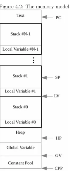
The implemented memory architecture is depicted in Figure 4.2, the right side of the picture shows some registers pointing to specific memory areas, while the CPP, the GV and the HP registers are common to all processors, each core has its own SP, LV and PC registers that define the computation status.
38 4. The Emulated Architecture
Figure 4.2: The memory model The addressing occurs via 32-bit words, thus the memory could be the-oretically 4 GB large. However, the GPU must store some further informa-tion in addiinforma-tion to the memory array and, as explained in chapter 3, graphic devices usually expose a memory hierar-chy where different memory areas can be accessed by different cores with different performances. The higher the number of core sharing a memory area is, the higher the resulting access time will be, GPUs expose both little and fast private memory areas and large but slow global memory areas.
Hence, the IJVM memory capacity must deal with the GPU memory ar-chitecture, that can varies between de-vices.
4.2
The emulation of the IJVM model
Previous sections have described the IJVM model, highlighting the fact that host systems are GPUs. This fact creates some restrictions in the de-velop of a many-core processor emulator. Since GPU cores usually implement a SIMD -like paradigm, the classic emulation approach that invokes a specific routine for each instruction is not well suitable. The parallel emulation of different instruction flows would cause GPU cores to diverge, losing parallel
4.2 The emulation of the IJVM model 39
power (see chapter 3 for more details).
GPGPU programming environments (like Brook, CUDA or OpenCL) ex-pose a SPMD (Single Program Multiple Data) paradigm [2], that makes each GPU core to execute the same program using its own Program Counter, thus each execution is independent from the others. However, this programming paradigm has to deal with the SIMD -like organization of the hardware. GPU cores are clustered into some groups, cores within the same group execute in a pure SIMD manner, but cores that belong to different groups can be considered autonomous. This “cluster organization” can be partially man-aged by programmer, but is always under the control of the adopted library, which arranges the execution flows according to some internal rules.
As a consequence, GPUs expose a massively parallel architecture that can partially support a MIMD -like execution. This thesis investigates how this MIMD -like execution can be exploited, comparing two different emulation approaches: the former emulates at the ISA level, implementing a specific routine for each ISA instruction (that is the classic approach). The latter moves one step lower in the abstraction stack (see Figure 4.1), implementing the Micro Architecture level where the computation is no longer expressed in terms of routine, but different memory words enable/disable specific com-ponents of the (emulated) processor. At this level, the emulation consists in the implementation of the processor components (registers selection, ALU computation, memory operations, ...) and the execution is always the same, regardless of which instruction has to be performed. Unlike ISA level emu-lation, this approach is suitable for GPU hardware, because SIMD-arranged cores can emulate the execution of different tasks implementing the same code.
Both approaches are implemented and compared, the latter (the Micro Architecture one) is improved exploiting the parallel computation power ex-posed by GPUs, leading to three distinct models:
ISA the classic emulation mode: every ISA instruction is implemented by an ad-hoc routine. Although it could be the more intuitive approach,
40 4. The Emulated Architecture
it presents a non trivial scalability issue: the more tasks are paral-lel emulated, the more they will diverge, leading to a sequential-like execution
MIC A precise emulation of the Micro Architecture model described in [14]: each task is emulated by the execution of the same code, making the ISA instructions implementation effort much more expensive, with a corresponding performance downgrade
PMIC (that stands for Parallel MIC ) it is an improved version of the MIC model. This refined architecture provides three distinct processing ele-ments for each instruction flow (that can perform up to three distinct operations in parallel)
These models are compared, in order to discover if and how GPUs are good device for an the emulation hosting; ISA emulation could obtain higher performance in terms of execution time, but it scales worse than MIC ap-proach.
Starting from these observations, it could be possible to develop a hybrid solution that mixes the GPU-suitability of the MIC model and the flexibility of the ISA model.
4.2.1
Evaluation
The two proposed approaches are compared and evaluated according to some measurements. The first one considers the number of processes concur-rently emulated as the variable factor and two different performance mea-sures: the average execution time per instruction and the global memory usage. Given N The former measures the time required for the execution of a single instruction. If an emulation run requires t seconds to be completed and the N processes are composed of n0, n1, .., nN −1instructions respectively,
4.2 The emulation of the IJVM model 41 T (N ) = t N −1 P i=0 ni (4.1)
The global execution time measurement depends on both the number of parallel processes and the amount of processes instructions. Since the latter factor does not affect the scalability of an emulation approach the execution time has been normalized according to the number of processes instructions, obtaining the execution time per instruction measurement.
The second evaluation is the global memory usage, it consists in the memory capacity required by an emulator, i.e. the Mega Bytes that have to be copied to the GPU buffers. Different approaches have different mem-ory requirements, typically Micro Architecture level emulation require more memory than the ISA level emulation, sinc the code has been translated into data. Hence, an execution time improvements can corresponds to a mem-ory occupation increase, that sometimes could be intractable (as explained above).
Chapter 5
ISA level emulation
This chapter presents the classic processor emulation approach, that per-mits an unmodified program compiled for a specific architecture to be exe-cuted on a different platform.
As discussed in chapter 2, “to emulate” means to provide an either hard-ware or softhard-ware system that exposes the same functionalities of the emu-lated system. The more intuitive approach for the development of a processor emulator considers the processor instructions as the primary entities to be emulated, for this reason this approach will be referred to as the Instruction Set Architecture (ISA) level emulation.
At this level the emulator provides an ad-hoc routine for each opcode belonging to the Instruction Set of the emulated processor, the processor image is described through specific data structures for the Registers block, the Main Memory and the Interrupt Vector.
5.1
The Fetch -Decode-Execute cycle
Given a target architecture (e.g. i386, arm, mips, ..) an emulator takes a program compiled for that platform as input and it mimics the Fetch-Decode-Execute (FDE ) cycle in this way:
Fetch it fetches a byte from the binary file
44 5. ISA level emulation
Decode it selects the right routine through a switch-like statement accord-ing to the fetched opcode
Execute it invokes the chosen routine, providing the processor image as input
If the adopted language permits the use of function pointers, the Decode and the Execute steps can be merged in a unique phase. Opcode routines can be referenced by a function pointers array opcode[], where the generic element opcode[i] points to the routine corresponding the opcode i.
These steps are repeated until there are no more opcodes to be fetched or a return-like statement is reached.
5.2
A parallel architecture emulator
The aim of this thesis is the development of a many-core architecture em-ulator such that multiple binary files can be taken as input and concurrently emulated. Thus, there will be several virtual Execution Units each of which emulates its own FDE loop.
In a single-core scenario, these Execution Units are treated as concurrent processes (or threads) that are interleaved on the processor core. Due to the high number of context switches, this approach leads to a big performance downgrade, that can be reduced using an either multi-core or many-core platform as the host system for the emulation. The emulator performs a many-to-many mapping from the virtual Execution Units to the real proces-sor cores.
This thesis investigates this approach, it implements a many-core emu-lator on the top of a Graphics Processor, the mapping is very simple since once an Execution Unit is scheduled on a GPU core, it performs all its com-putation on that core, reducing the mapping time.
As discussed in previous chapters, GPU cores are arranged in SIMD groups, within which they are forced to simultaneously execute the same
5.2 A parallel architecture emulator 45
instructions sequence using different memory portions. Thus, the parallel emulation of multiple execution flows is not trivial, indeed given N input pro-grams to emulate, for each of them there will be a dedicated Execution Unit, which iterates the Fetch, the Decode and the Execute phases. Though the first two steps (Fetch and Decode) could be easily emulated on N SIMD cores (all cores would perform the same instructions sequence for these steps), the Execute phase always requires different instructions to be performed, leading to a divergent execution.
To address this issue, this thesis proposes a new emulation technique, that will be detailed described in the next chapter; this new approach consists in a unique routine R where each opcode is treated as a processor configuration that allow R to behave differently depending on the opcode. It is important to claim that GPGPU libraries usually apply some policies when scheduling parallel threads on GPU cores, in order to reduce the divergent phenomena as much as possible.
For this reason, both emulation techniques are implemented and com-pared.
5.2.1
Improvements for the ISA emulation
The ISA level emulation is based on a mature technology, with a lot of innovations proposed during recent years (see chapter 2). For example, the Qemu machine emulator implements a combination of static compilation and dynamic translation to achieve high performance [17].
However, this technique cannot be direct implemented on the top of a GPU since this kind of device does not allow all programming techniques that are commonly available in the classic CPU programming (e.g., function pointers); moreover some new techniques need to be introduced in order to address the divergence phenomena; in [11], a many-core emulator is developed on the top of a GPU, introducing a further compilation step where the input program is compiled to a new ISA with a very limited number of instructions, in order to reduce the divergence probability.
![Figure 3.1: A schematic vision of the RV710 GPU architecture, taken from [3]](https://thumb-eu.123doks.com/thumbv2/123dokorg/7470732.102379/30.892.255.583.255.559/figure-schematic-vision-rv-gpu-architecture-taken.webp)
![Figure 3.2: The OpenCL execution model, taken from [28]](https://thumb-eu.123doks.com/thumbv2/123dokorg/7470732.102379/37.892.197.658.654.929/figure-opencl-execution-model-taken.webp)
![Figure 3.3: A 2D Work-Group example, taken from [28]](https://thumb-eu.123doks.com/thumbv2/123dokorg/7470732.102379/39.892.199.653.208.503/figure-d-work-group-example-taken.webp)
![Figure 3.4: The OpenCL memory model, taken from [28]](https://thumb-eu.123doks.com/thumbv2/123dokorg/7470732.102379/40.892.230.662.553.982/figure-opencl-memory-model-taken.webp)
![Figure 4.1: The multilevel structure of Computer defined in [14]](https://thumb-eu.123doks.com/thumbv2/123dokorg/7470732.102379/46.892.202.698.200.561/figure-multilevel-structure-computer-defined.webp)
![Figure 6.1: The Mic-1 execution Path, taken from [14]](https://thumb-eu.123doks.com/thumbv2/123dokorg/7470732.102379/62.892.231.646.470.918/figure-mic-execution-path-taken.webp)
![Figure 6.2: The Micro-instruction structure, taken from [14]](https://thumb-eu.123doks.com/thumbv2/123dokorg/7470732.102379/63.892.165.692.422.685/figure-the-micro-instruction-structure-taken-from.webp)