Abstract
A pilot power system formed by photovoltaic panels, alkaline elec-trolyser and fuel cell stacks was designed and set up to supply the heat-ing system of an experimental greenhouse. The aim of this paper is to analyse the main safety aspects of this power system connected to the management of the pressured hydrogen, such as the explosion limits of the mixture hydrogen-oxygen, the extension of the danger zone, the protection pressure vessels and the system to make unreactive the plant. The electrolyser unit is the core of this plant and from the safety point of view has been equipped with devices able to highlight the mal-functions before they cause damages. Alarm situations are highlighted and the production process is cut off in safe conditions in the event that the operational parameters have an abnormal deviation from the design values. Also the entire power system has been designed so that any failure to its components does not compromise the workers’ safety even if the risk analysis is in progress because technical operations
are being carried out for enhancing the plant functionality, making it more suitable to the designed task of supplying electrically the green-house heating system during cold periods. Some experimental data pertinent to the solar radiation and the corresponding hydrogen pro-duction rate are also reported. At present it does not exist a well-estab-lished safety reference protocol to design the reliability of these types of power plants and then the assumed safety measures even if related to the achieved pilot installation, can represent an original base of ref-erence to set up guidelines for designing the safety of power plants in the future available for agricultural purposes.
Introduction
The peculiar changeability and unstable usefulness of renewable energy sources usually restrict their wider adoption (Jallouli and Krichen, 2012) and to overcome this limit the renewable energy based systems are equipped with a power back up usually composed by bat-teries that unfortunately have short lifetime and low energy storage capacity. Nowadays solar systems can be provided with power back up based on a combination of an electrolyser and a fuel cell stack so to generate high purity hydrogen gas through water electrolysis process (David, 2005). Produced hydrogen acts as an energy vector that can accumulate the photovoltaic energy exceeding the current demand, and it can be used to generate power later by means of fuel cell. Hydrogen production systems powered by stand-alone photovoltaic generators can contribute to improve living standards in rural areas not yet supplied with electric grid, avoiding expensive investments for a single electric grid implementation (Valdés et al., 2012). These plants can operate reliably under dynamic solar irradiance and dynam-ic loads, even though the global effdynam-iciency of such systems is very low (less than 5%) mainly owing to the operating performance of the pho-tovoltaic panels (Maclay et al., 2011). Presently worldwide hydrogen production is set up on fossil sources using natural gas reforming process or coal gasification (Mueller-Langer et al., 2007) but hydrogen can be also manufactured by biomass thermal processing or by biolog-ical methods (Redwood et al., 2009). Water electrolysis is the only one without carbon dioxide emissions in atmosphere and it produces zero emissions if linked to electricity obtained by renewable sources (Chai et al., 2012; Valdés et al., 2012). Hydrogen produced with this process is stored in pressurized gas cylinders and can be used to supply elec-tricity for various farming applications. The use of solar hydrogen power systems can provide a possible option for powering stand-alone greenhouses (Ganguly et al., 2010), which are widespread, especially in the areas with unfavourable climatic conditions (von Zabeltitz, 1999; Baldoin et al., 2008; Giacomelli et al., 2012). Really the storage of solar energy in the form of hydrogen (H2) can be the basis for a totally renewable system, composed by photovoltaic panels in combination Correspondence: Simone Pascuzzi, Department of Agricultural and
Environmental Science, University Aldo Moro of Bari, via Amendola 165/A, 70126, Bari, Italy.
Tel./Fax: +39.080.5442214. E-mail: [email protected]
Key words: Safety; hydrogen hazards assessment; water electrolysis; agricul-tural equipment.
Funding: the present work has been carried out under the project Integrated
production of energy from renewable sources within the Apulia Region (Italy) agricultural-industrial system - Networks of public research laborato-ries (project code RTL 01) co-funded by the Apulia Region under the
Agreement of Framework Program concerning the Scientific Research - PO
Apulia FESR 2007-2013, Axis I, Line 1.2 - PO Apulia FSE 2007-2013 Axis IV.
Contributions: the authors contributed equally. Received for publication: 19 August 2015. Accepted for publication: 23 October 2015.
©Copyright S. Pascuzzi et al., 2016 Licensee PAGEPress, Italy
Journal of Agricultural Engineering 2016; XLVII:507 doi:10.4081/jae.2016.507
This article is distributed under the terms of the Creative Commons Attribution Noncommercial License (by-nc 4.0) which permits any noncom-mercial use, distribution, and reproduction in any medium, provided the orig-inal author(s) and source are credited.
Hazards assessment and technical actions due to the production
of pressured hydrogen within a pilot photovoltaic-electrolyser-fuel cell
power system for agricultural equipment
Simone Pascuzzi, Ileana Blanco, Alexandros Sotirios Anifantis, Giacomo Scarascia-Mugnozza
Department of Agricultural and Environmental Science, University Aldo Moro of Bari, Italy
Non
commercial
use
with hydrogen produced by electrolysis, H2-storage and fuel cells con-nected to a ground source heat pump (Kondili and Kaldellis, 2006). The geothermal heating systems with heat pump may be useful, environ-mental friendly and economically favourable to meet energy require-ments of modern greenhouses for winter heating systems pushing up the sustainability of the covered cultivations (Vox et al., 2010; Scarascia-Mugnozza et al., 2011; Benli, 2013).
The Authors are carrying out a research with the aim to investigate the suitable solutions of a power system, based on solar energy (photo-voltaic) and hydrogen, supporting a self-sustained greenhouse of 48 m2
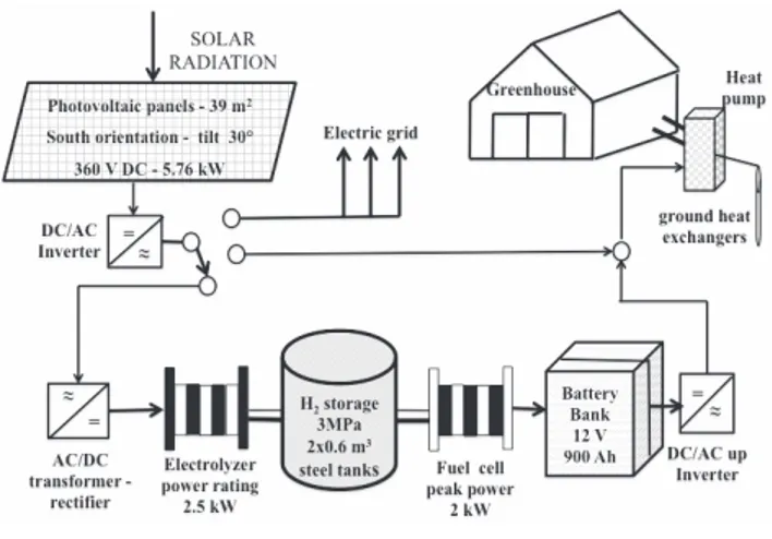
heated with a geothermal heat pump. The study is going on at the experimental farm of the University of Bari (latitude 41° 01’ 12.2” N, longitude 16° 54’ 16.3” E), where a pilot power system integrated with a greenhouse composed of photovoltaic panels, an alkaline electrolyser bank, fuel cell stacks, a plastic greenhouse and a geothermal heat pump were designed and set up (Figure 1). The electricity coming from the solar photovoltaic source (PV) feeds the water electrolyser and the produced hydrogen is then stored in a pressured tank (Blanco et al., 2013). When the PV is inactive (during night time or overcast sky), H2 is consumed by the fuel cell producing electricity based on the green-house energy demands (Blanco et al., 2014).
The design of this pilot plant has also affected the safety aspects tak-ing into account that the management of the pressured gases requires a careful risks analysis to safeguard the farmer operators that must be trained to be aware of potential hazards and to take appropriate precau-tions.
According to this, this paper analyses the main safety aspects of the pilot power system connected to the management of the pressured hydrogen and the pertinent designed and assembled technical actions in order to reduce the hazards. Therefore in order to minimize the operators’ risks the protection pressure vessels, the system to make unreactive the plant and the extension of the danger zone have been carefully studied.
At present it does not exist a well-established safety reference proto-col to design the reliability of these types of power plants and then the assumed safety measures even if related to the achieved pilot installa-tion, can represent an original base of reference to set up guidelines for designing the safety of power plants in the future available for agri-cultural purposes. Finally some experimental data pertinent to the solar radiation and the corresponding hydrogen production rate are reported as example of the performance of the electrolyser.
Materials and methods
The assembled pilot power system
The pilot power system was designed and assembled with the pur-pose of using the PV both directly, when the photovoltaic energy pro-duction and the greenhouse energy demands are simultaneous, and when there is no greenhouse energy demand so that the photovoltaic production can be used for the hydrogen production and storage (Figure 1). The designed passive loads are seasonally dependent.
The array of photovoltaic panels consists of 24 modules grouped in order to achieve a nominal voltage of 360 V and 5.76 kW pick power. The electric power produced by the PV modules is converted to alternate current (AC) power by an inverter so to feed directly the heat pump of the greenhouse or the grid if necessary (Figure 1). Conversely another power converter allows transforming the alternating current into direct current (DC) of intensity and characteristics suitable for the process of electrolysis (Figure 1). The electrolyser is supplied by a power rating of 2.5 kW at a voltage of 230 VDC and produces a hydrogen nominal rate
(dry gas) of 0.4 Nm3 h–1at 3 MPa (Sioli, 2014). The electrolyser is made
of 33 bipolar circular cells connected in series, fitted with frames con-taining channels for the distribution of the electrolyte and further channels for the collection of the electrolysis products. Each cell has an active area of 10–4 m2 and comprises an anode and a cathode separated
by a diaphragm. The electrolyte is a potassium hydroxide solution (KOH concentration 28% w) and the amount of electrolyte loaded is 30 L. The electrolyser depletes 45×10–5m3h–1of demineralized water at
full load.
Hydrogen and oxygen bubbles generated in the electrolyser are col-lected in two separate channels and conveyed into the purification sys-tem, which begins with the gas separators. These are two stainless steel cylindrical recipients half filled with electrolyte where the pro-duced gases are separated from the liquid. The two gases are then fil-tered and conveyed to cross final droplets separators before be deliv-ered from the unit. Hydrogen is routed through a backpressure con-troller; oxygen is vented to the atmosphere. The produced pressurized hydrogen is stored inside two steel tanks having a total capacity of 0.6 m3. Pressured nitrogen hold inside metallic cylinders is employed to
make unreactive the plant before each restarting of the electrolyser. The fuel cell system has a peak power of 2 kW and for its working requires industrial grade hydrogen (99.95%) and oxygen (air). The energy produced by the fuel cells charges a bank composed by six lead/gel batteries in series-parallel interconnected with a global capac-ity of 900 Ah. Another inverter is connected to the battery terminals in order to be used as a stand-alone sinusoidal AC voltage provider. A con-trol system mainly composed by the programmable logic concon-troller (PLC) Horner PLC XL6 OCS manages and supervises the different phases of the process concerning the generation and purification of the produced hydrogen by the electrolyser, the hydrogen storage and the electric production ensuring reliable safe and efficient effectiveness.
Main current safety and technical regulations
perti-nent to the assembled power plant
The devices, pipes and systems pertinent to the hydrogen generation have to be complied with both the ATEX (Atmosphères Explosibles) directives concerning the hydrogen equipments that are 94/9/EC and 99/92/EC (European Commission, 1994, 1999). The directive 94/9/CE establishes the technical requirements for equipment and protective system intended for use in potentially explosive atmospheres, whereas
Figure 1. Integrated power system layout.
Non
commercial
use
the directive 1999/92/CE formulates minimum requirements for the safety and health protection of workers potentially at risk from explo-sive atmospheres. These instructions define as exploexplo-sive atmosphere a mixture with air of dangerous substances in the form of gases, vapour, mist or dust in which after ignition has occurred, combustion spreads to the entire unburned mixture. According to this statement, to deter-mine a possible presence of atmospheres explosive in an activity, pro-vided that flammable substances mixed with the air in the right propor-tions (mixing inside the flammable range) are present accidentally or during normal working conditions. In Italy the provisions of ATEX Directives were faithfully implemented by the Regulation regarding the workplaces health and safety (Italian Regulation, 2008) and in such cases, in order to avoid explosions, the employer according to a risk assessment must adopt the technical and organizing measures suitable to the type of the activity carried out. In particular, he must avoid the ignition of explosive atmospheres and attenuate the injurious effects of an explosion. In addition, the ATEX classify places where explosive atmospheres can occur into zones and the classification is made according to frequency and duration of explosive atmosphere through the number 0,1,2. The design of the hydrogen production process has been carried out according to the current technical standard ISO 22734-1:2008, which defines the construction, safety and performance requirements of hydrogen generators (ISO, 2008). Finally also the instructions PED (Pressure Equipment Directive), concerning the avail-ability on the market of pressure equipment have been complied (European Commission, 2014).
Hazard study connected to the electrolyser working
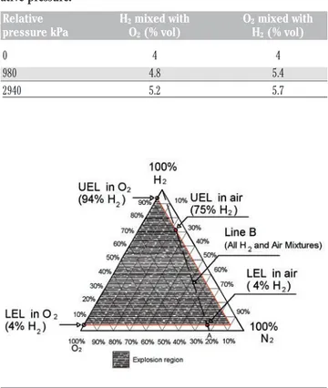
The electrochemical reaction concerning the water splitting into hydrogen (H2) and oxygen (O2) takes place when a suitable DC elec-tric current is applied to the electrodes of the electrolyser (Atkins, 1990). In an electrolysis cell an electric current moves between two electrodes separated by a diaphragm and conductive electrolyte, pro-ducing hydrogen at the negative electrode (cathode) and oxygen at the positive electrode (anode). As water is H2O, twice the volume of hydrogen is produced for each volume of oxygen. The gases produced by this process are mutually impure, because of the diffusion phe-nomenon through the diaphragm of the electrolysis cell (Buttner et al., 2011). The diffusion takes place in the pores of the diaphragm through the liquid phase of the electrolyte and is due to the tendency of hydrogen to migrate from the cathode sectors, in which the elec-trolyte is saturated with this gas, to the anodic sectors, in which con-versely the electrolyte is lacking of hydrogen (Atkins, 1990). Clearly oxygen migrates in reverse way that is from anodic sectors to cathode ones (Atkins, 1990). The mutual mixing of these two gases, beyond specified limits, may lead to the formation of explosive mixtures (ISO, 2004). As known before a fire or explosion occurs, three condi-tions must be met simultaneously. A fuel (i.e., combustible gas) and oxygen (air) must exist in certain proportions, along with an ignition source, such as a spark or flame (Atkins, 1990). The required ratio fuel/oxygen varies with each combustible gas or vapour. The mini-mum concentration of a particular combustible gas or vapour neces-sary to support its combustion in air is defined as the lower explosive limit (LEL) for that gas (Ng and Lee, 2008). Below this level, the mix-ture is too lean to burn. The maximum concentration of a gas or vapour that will burn in air is defined as the upper explosive limit (UEL) (Molnárné et al., 2005). Above this level, the mixture is too rich to burn. The range between the LEL and UEL is known as the explo-sion region for that gas or vapour (Molnárné et al., 2003). Usually the concentrations are in per cent by volume. The conventional limits for hydrogen in air are: LEL=4.0%; UEL=75% (Atkins, 1990). The tertiary diagram for hydrogen, oxygen and nitrogen including the explosion
envelope at temperature of 20°C and absolute pressure of 101.325 kPa is shown in Figure 2, which is read as follow: the top (apex) of trian-gle represents 100% hydrogen an the base of the triantrian-gle represents 0% hydrogen (Molnárné et al., 2003; ISO, 2004). The lower right cor-ner is 100% nitrogen and the lower left corcor-ner is 100% oxygen. Mixtures inside the envelope are explosive. Line B is drawn from air (Point A in Figure 2) to 100% hydrogen and thus any mixture of hydrogen and air alone must lie on Line B. The aforesaid LEL and UEL points for hydrogen in air are also marked out on line B. Furthermore note the LEL and UEL of hydrogen mixed with oxygen (4% hydrogen and 94% hydrogen, respectively). Temperature and pressure affect these limits: in particular both LEL of hydrogen into oxygen and oxy-gen into hydrooxy-gen trend to reduce raising the temperature from 20 to 80°C and Table 1 reports the safety characteristics measured at 80°C (Molnárné and Schröder, 2011). Therefore for safety purposes it is necessary to respect these thresholds also considering the margins of uncertainty of their definition.
The technical standard (ISO, 2008) requires that the electrolysis process must be stopped at the fulfilment of 2% of H2mixed with O2 (50% of LEL at atmospheric pressure) and 1.6% of O2mixed with H2 (40% of LEL at atmospheric pressure) regardless to temperature and pressure values. Regarding the effects of explosions, in the case of H2 mixed with O2the overcoming of few units% of the LEL produces a very restrained effect because the explosion occurs in conditions of little concentrated fuel. Conversely, the effect is much more disastrous in the case of O2mixed with H2because the hydrogen is prevailing and then the choice of a lower threshold than the corresponding LEL.
Figure 2. Tertiary diagram for hydrogen, oxygen and nitrogen, with explosively envelope at temperature of 20°C and absolute pressure of 101.3 kPa (ISO, 2004). UEL, upper explosive limit; LEL, lower explosive limit.
Table 1. Lower explosive limit evaluated at 80°C for different rel-ative pressure.
Relative H2mixed with O2mixed with pressure kPa O2(% vol) H2(% vol)
0 4 4 980 4.8 5.4 2940 5.2 5.7
Non
commercial
use
only
Experimental data
The solar radiation influences significantly the hydrogen production rate. The PLC Horner continuously checks these two parameters with sampling frequency of 1 minute through the electric signals respective-ly sent by a solarimeter and a mass flow meter. In particular the radia-tion level of solar exposure is evaluated through the sensor SunMeter equipped with a monocrystalline silicon cell whose main technical fea-tures are: input range: irradiation 0-1250 Wm–2, spectral range 0.3-1.1
m, temperature –30/80°C; output precision: irradiation ±2.5%, temper-ature ±1°C. Conversely the main characteristics of the mass flow meter Bronkhorst (Ruurlo, The Netherlands) model Select MFM F-111BI are: accuracy: standard ±0.5% Rd(reading) plus ±0.1% FS (full scale); turn-down: 1:50; repeatability: <0.2% Rd. The data relevant to the solar radi-ation and the corresponding hydrogen production rate of the electrol-yser registered during a day characterized by unstable solar radiation are reported.
Results and discussion
The equipment was designed and set up according to the current safety and technical regulations in order to reduce the hazards and the farmer operators’ accident using also avant-garde devices. In particular the process and control areas of the pilot power system have been locat-ed in distinct rooms separatlocat-ed by a watertight bulkhead inside the con-tainer, whereas obviously the photovoltaic panels and the pressured steel tanks have been placed outdoor (Figure 3). These last ones have been installed on a reinforced concrete foundation and are shaded by a metallic shelter (Figure 4). Also the container has been constrained at its corners with reinforced concrete foundations (Figure 3). Inside the container the process room fundamentally includes the electrolysis unit and the fuel cell stack, whereas the control room comprises the cabinet PLC, the battery bank, the inverters and the electric patch and control boards. The electrolyser has been located inside a metallic cab-inet equipped with a system for the air extraction. Suitable openings have been made in the lower part of the cabinet to suck the outside air, which is then withdrawn at the top by a suitable fan. In this way, the area classified as dangerous is restricted inside the cabinet and evalu-ated as Zone 2 that is a place in which an explosive atmosphere is not likely to occur in normal operation but, if it does occur, will persist for a short period only (European Commission, 1994; ISO, 2008). A device controls if the atmosphere inside the cabinet is able to explode giving an alarm signal if H2into air reaches a concentration of 10% of LEL and cutting off the electrolysis process if the aforesaid concentration comes to 30% of LEL. In case of hydrogen discharge, the control system put out potential the electrical components not consistent with the Zone 2, whereas feeds only the electrical components conformable with it such as those linked to the process or intended to carry out the safety oper-ations. The fan air extraction is equipped with an electric engine suit-able for working in presence of hydrogen. From the electrical point of view, besides, the cathode head of the electrolyser has been wired directly to the earthing electrode by a cable and then also all the pipes are connected to the ground because these ones are linked to the cath-ode head of the stack. Also the instrumentation placed inside the con-trol room have been wired to ground through a second cable. A suitable uninterruptible power supply (UPS) feeds the control system if a lack of electricity occurs so to carry out the procedure to restore the system in safe conditions. According to the technical standard, the electrolyser and all the vessels stressed by internal pressure are protected against overpressure through safety valves (European Commission, 2014). In addition to these mechanical devices, three active safety levels with
selective trigger thresholds have been designed and assembled to reduce the operators’ hazards. The first level is pertinent to the soft-ware and then, taking into account that the operative pressure of the electrolyser is 3 MPa, the PLC automatically reduces the power to 50% if the pressure increases to 3.15 MPa. Furthermore if the pressure increases again beyond the 3.25 MPa, despite the reduction of the load, the electrolyser cuts off the hydrogen production and automatically goes into the stand-by pressurized state. The second level is of electro-mechanical type and its action occurs if the previous level has been unable to handle the increased pressure. Therefore at 3.3 MPa a pres-sure switch mechanically cuts off the electric feed to the electrolyser and discharges a fraction of the electrolysis gases so to bring the sys-tem to a pressure less than 3 MPa. The syssys-tem restarts with the normal production if other alarms do not take place. The third level is activated if also the second level should fail. At a pressure of 3.5 MPa a safety valve discharges into the atmosphere the gas amount necessary to avoid overpressure inside the tank. The control system is also equipped with three buttons emergency stop placed respectively in the control room, in the process room and off the container. Pressing the emer-gency stop, the production is cut off at once and gases contained inside the electrolyser are discharged into the environment. Furthermore it is also broken the electric feed in the control room and the depressuriza-tion process is carried out through the UPS.
During the hydrogen generation process an analyser of O2mixed with H2located on the production line (Table 2), gives an alarm signal or cut off the electrolysis process if the concentration of O2mixed with H2 reaches, respectively, 1.1% and 1.6%. The hydrogen sample is extracted upstream of the purification system, depressurized, drained and conveyed to the sensor through a flow meter that ensures the
Figure 3. Pilot plant layout.
Table 2. Main technical characteristics of O2 mixed with H2 analyser.
Alarm threshold + cut off process 1.6 %O2 First warning alarm 1.1 %O2 Continuous concentration control signal 4-20 mA Hydrogen consumption 1 L min-–1
Max operative pressure 101.3 kPa Gas discharge Chimney
Non
commercial
use
appropriate flow to the analyser. Once tested, the sample is released into the atmosphere. The tertiary diagram of Figure 2 is useful to devel-op a methodology for the dilution of mixtures rich in hydrogen to avoid an explosion hazard. Suppose that a loss of hydrogen has filled an envi-ronment (room, vessels, piping and so on) to a final concentration of 80% by volume, thus realizing a mixture represented by point B of Figure 5. If one were merely to let air into this environment, the point B would move along the segment BA, so crossing the explosion region and the risk that any trigger face starting an explosion. Then it is better to enter in the environment pure nitrogen, moving on the segment B-100%N2, up to reach the mixture of type C, that is, the mixture that with the minimum nitrogen addition allows, with subsequent dilution with air, to move along the segment CA which is only tangent to the region of explosion. According to this methodology, before each restarting of the electrolyser nitrogen is employed to make unreactive the plant removing hydrogen and air inside the system. This operation is carried out automatically pressing the emergency stop button. The pressured nitrogen retained inside metallic cylinders, is depressurized to work inside the electrolyser at low pressure (max 0.5 MPa). A pressure switch connected to the PLC controls the residual pressure inside the nitrogen cylinders and if this last one pulls down below a threshold value cut off the hydrogen production of the plant. Finally, in case of malfunction potentially dangerous (or critical alarm) the electrolysis process is stopped automatically. Hydrogen and oxygen are gradually vented to avoid the danger of their mixing and nitrogen is automatical-ly injected when the pressure becomes close to the atmospheric.
Finally Figure 6 reports the solar radiation and the hydrogen produc-tion rate registered during a day characterized by partially cloudy sky (24thApril, 2015). The obtained results highlight an unstable hydrogen
production rate caused by the fluctuations of the solar radiation that affected the working of the electrolyser compelling it to operate contin-uously in a transient state.
Conclusions
The photovoltaic-electrolyser-fuel cell pilot power system aimed at supplying the heating system of an experimental greenhouse has been designed and set up so that any failure to its components does not com-promise the safety of the plant. The main aspects linked to the safety during the production of pressured hydrogen have been analysed in this paper, such as the explosion limits of the mixture hydrogen-oxygen and the extension of the danger zone, the protection pressure vessels
Figure 4. Pilot power plant external layout.
Figure 5. Dilution of mixtures rich in hydrogen to avoid an explosion hazard.
Figure 6. Solar radiation and hydrogen production rate during a day with partially cloudy sky.
Non
commercial
use
and the system to make unreactive the plant. In the assembled pilot power system alarm situations are highlighted and the production process is cut off in safe conditions in the event that the operational parameters have an abnormal deviation from the design values. The reasons that have caused alarm are highlighted and the operator is called for an inspection. The system can be reactivated after the repair just if the cause of malfunctioning has been effectively removed. The electrolyser is the heart of this plant and requires remarkable attention during its operation. From the safety point of view the electrolyser unit has been equipped with devices able to highlight the malfunctions before they cause damages to the operators and break off the process of hydrogen production. The management of the products of the elec-trolysis process also involves forethought and trained operators. The risk analysis of the power system is in progress because technical oper-ations are being carried out for enhancing the plant functionality, mak-ing it more suitable to the designed task of supplymak-ing electrically the greenhouse heating system during cold periods.
References
Atkins P.W. 1990. Physical chemistry, 4th ed. Oxford University Press, Oxford, UK.
Baldoin C., Balsari P., Cerruto E., Pascuzzi S., Raffaelli M. 2008. Improvement in pesticide application on greenhouse crops: Results of a survey about greenhouse structures in Italy. Acta Hort. 801:609-14.
Benli H. 2013. A performance comparison between a horizontal source and a vertical source heat pump systems for a greenhouse heating in the mild climate Elazig, Turkey. Appl. Therm. Eng. 50:197-206. Blanco I., Anifantis A.S., Pascuzzi S., Scarascia-Mugnozza G. 2013.
Hydrogen and renewable energy sources integrated system for greenhouse heating. J. Agr. Eng. 44:226-30.
Blanco I., Pascuzzi S., Anifantis A.S., Scarascia-Mugnozza G. 2014. Study of a pilot photovoltaic-electrolyzer-fuel cell power system for a geothermal heat pump heated greenhouse and evaluation of the electrolyzer efficiency and operational mode. J. Agr. Eng. 45:111-8. Buttner W.J., Post M.B., Burgess R., Rivkin C. 2011. An overview of hydrogen safety sensors and requirements. Int. J. Hydrogen Energ. 36:2462-70.
Chai L., Ma C., Ni J.Q. 2012. Performance evaluation of ground source heat pump system for greenhouse heating in norther China. Biosyst. Eng. III:107-17.
David E. 2005. An overview of advanced materials for hydrogen storage. J. Mater. Process. Technol. 162-163:169-77.
European Commission, 1994. Directive of the European Parliament and the Council of 23 March 1994 on the approximation of the laws of the Member States concerning equipment and protective systems intended for use in potentially explosive atmospheres, 94/9/EC. In: Official Journal, L 100, 19/04/1994, pp 1-29.
European Commission, 1999. Directive of the European Parliament and the Council of 16 December 1999 on minimum requirements for improving the safety and health protection of workers potentially at risk from explosive atmospheres, 99/92/EC. In: Official Journal, L 23, 28/01/2000, pp 57-64.
European Commission, 2014. Directive of the European Parliament and of the Council of 15 May 2014 on the harmonisation of the laws of the Member States relating to the making available on the market of pressure equipment, 2014/68/EU. In: Official Journal, L 189, 27/06/2014, pp 164-259.
Ganguly A., Misra D., Ghosh S. 2010. Modeling and analysis of solar photovoltaic-electrolyzer-fuel cell hybrid power system integrated
with a floriculture greenhouse, Energ. Buildings. 42:2036-43. Giacomelli G.A., Sase S., Cramer R., Hoogeboom J., MacKenzie A.,
Parbst K., Scarascia-Mugnozza G., Selina P., Sharp D.A., Voogt J.O., Van Weel P.A., Mears D. 2012. Greenhouse production systems for people. Acta Hort. 927:23-38.
ISO, 2004. Basic considerations for the safety of hydrogen systems. Norm ISO/TR 15916:2004. International Organization for Standardization Publ., Geneva, Switzerland.
ISO, 2008. Hydrogen generators using water electrolysis process - Part 1: Industrial and commercial applications. Norm ISO 22734-1:2008. International Organization for Standardization Publ., Geneva, Switzerland.
Italian Regulation, 2008. Code on health and safety protection of employees in the workplace. LD 81/2008. In: Official Journal No. 101, 30/04/2008, pp 5-24; Official Journal No. 180, 05/08/2009. Jallouli R., Krichen L. 2012. Sizing, techno-economic and generation
management analysis of a stand alone photovoltaic power unit including storage devices. Energy 40:196-209.
Kondili E., Kaldellis J.K. 2006. Optimal design of geothermal-solar greenhouses for the minimisation of fossil fuel consumption. Appl. Therm. Eng. 26:905-15.
Maclay J.D., Brouwer J., Samuelsen G.S. 2011. Experimental results for hybrid energy storage systems coupled to photovoltaic generation in residential applications. Int. J. Hydrogen Energ. 36:12130-40. Molnárné M., Mizsey P., Schröder V. 2005. Flammability of gas mixtures.
Part 2: Influence of inert gases. J. Hazard. Mater. A121:45-9. Molnárné M., Schendler T., Schröder V. 2003. Sicherheitstechnische
Kenngrö en, Band 2: Explosionsbereiche von Gasgemischen. Wirtschaftsverlag NW, Bremerhaven, Germany.
Molnárné M., Schröder V. 2011. Comparison of calculated data for flam-mability and the oxidation potential according to ISO 1156 with experimentally determined values. J. Loss Prev. Process Ind. 24:900-7.
Mueller-Langer F., Tzimas E., Kaltschmitt M., Peteves S. 2007. Techno-economic assessment of hydrogen production processes for the hydrogen economy for the short and medium term. Int. J. Hydrog. Energ. 32:3797-810.
Ng H.D., Lee J.H.S. 2008. Comments on explosion problems for hydro-gen safety. J. Loss Prevent. Process Industr. 21:136-46.
Redwood M.D., Paterson-Beedle M., Macaskie L.E. 2009. Integrating dark and light bio-hydrogen production strategies: towards the hydrogen economy. Rev. Environ. Sci. Bio. 8:149-85.
Scarascia-Mugnozza, G., Pascuzzi, S., Anifantis, A., Verdiani, G. 2011. Photovoltaic and geothermal integration system for greenhouse heating: an experimental study. Not numbered volumes pp. 135-138 in Proc. 5th Int. Sci. Symp. Farm Machinery and Process Management in Sustainable Agriculture, Lublin, Poland.
Sioli G. 2014. High pressure electrolyzer, United States Patent. Available from: http://worldwide.espacenet.com/publicationDetails/ biblio;jsessionid=3B8961542034B3972FAFF4E13987BBC4.espacen et_levelx_prod_2?FT=D&date=20100506&DB=&&CC=CA&NR=2 739019A1&KC=A1&ND=1&locale=en_EP Accessed: May 2014. Valdés R., Rodríguez L.R., Lucio J.H. 2012. Procedure for optimal design of
hydrogen production plants with reserve storage and a stand-alone photovoltaic power system. Int. J. Hydrogen Energ. 37:4018-25. von Zabeltitz C. 1999. Chapter 2: Greenhouse structures. In: G. Stanhill
and H. Zvi Enoch (Eds.), Greenhouse ecosystems. Elsevier, Amsterdam, Netherlands, pp. 17-69.
Vox G., Teitel M., Pardossi A., Minuto A., Tinivella F., Schettini E. 2010. Chapter 1: Sustainable greenhouse systems, sustainable agricul-ture: technology, planning and management. Nova Science Publishers, New York, NY, USA.