ALMA MATER STUDIORUM
UNIVERSIT `
A DEGLI STUDI DI BOLOGNA
Scuola di Ingegneria e Architettura
Corso di Laurea in Ingegneria elettronica, informatica e
telecomunicazioni
AGENTS, NODES & RESOURCES: UNIVERSAL
NAMING SYSTEM FOR A COORDINATION
MIDDLEWARE
Elaborata nel corso di: Sistemi Distribuiti
Relatore:
Prof. ANDREA OMICINI
Co-relatori:
ING. STEFANO MARIANI
Tesi di Laurea di:
FEDERICO FOSCHINI
ANNO ACCADEMICO 2012–2013
SESSIONE II
PAROLE CHIAVE
TuCSoN Cassandra Naming Locator Research”Don’t waste time living someone else’s life.
Stay hungry. Stay Foolish.”
Contents
Introduction xi
1 Background knowledge 1
1.1 What is TuCSoN ? . . . 1
1.2 Tuple Centre . . . 1
1.2.1 The tuple based coordination model . . . 4
1.2.2 Tuple Spaces . . . 5
1.2.3 Limitations of Tuple Spaces . . . 6
1.2.4 From Tuple Spaces to Tuple Centres . . . 7
1.2.5 Tuple Centre Definition . . . 8
1.3 Model, language, architecture and technology in TuCSoN . . 9
1.3.1 TuCSoN Model . . . 9
1.3.2 Naming in TuCSoN . . . 10
1.3.3 TuCSoN Language . . . 11
1.3.4 TuCSoN Architecture . . . 12
1.3.5 TuCSoN Coordination Space . . . 13
1.3.6 TuCSoN Technology . . . 14
1.4 Background Knowledge for Cassandra . . . 16
1.4.1 CAP Theorem . . . 16
1.4.2 Variation over CAP Theorem . . . 18
1.4.3 Limits of RDBMS . . . 19
1.5 Cassandra . . . 21
1.5.1 Data Model . . . 22
1.5.2 Data Distribution Model . . . 23
2 JADE 29
2.1 What is JADE . . . 29
2.2 JADE Architecture . . . 30
2.2.1 JADE & FIPA . . . 31
2.2.2 JADE Agents . . . 33
2.2.3 FIPA ACC . . . 37
3 Naming, Locator & Research Service Structure & Interaction Model 41 3.1 Main Model . . . 42
3.2 Naming Service Model . . . 44
3.2.1 Outside Interfacing Layer . . . 45
3.2.2 Internal Request Computation Layer . . . 47
3.2.3 Data Storage Layer . . . 51
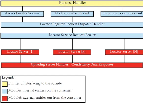
3.3 Locator Service Model . . . 54
3.3.1 Outside Interfacing Layer . . . 55
3.3.2 Internal Request Computation Layer . . . 57
3.3.3 Data Storage Layer . . . 61
3.4 Research Service Model . . . 64
3.4.1 Outside Interfacing Layer . . . 65
3.4.2 Internal Request Computation Layer . . . 67
4 Universal Naming Syntax 73 4.1 Syntax Definition . . . 75
4.2 Naming System Syntax Procedure . . . 76
5 Case Studies 79 5.1 Naming Service System Case Study . . . 81
5.1.1 Local Naming Service System Case Study . . . 82
5.1.2 Distributed Naming Service System Case Study . . . 91
5.2 Locator Service System Case Study . . . 100
5.2.1 Local Locator Service System Case Study . . . 101
5.2.2 Distributed Locator Service System Case Study . . . 110
5.3 Research Service System Case Study . . . 119
5.3.1 Local Research Service System Case Study . . . 120
5.3.2 Distributed Research Service System Case Study . . 124
5.5 Fault Tolerance Case Study:
Internal Entities Crash . . . 130 5.6 Fault Tolerance Case Study:
Unavailable Connection between
Internal Entities . . . 132 5.7 Fault Tolerance Case Study:
Unavailable Network Connection . . . 134 5.7.1 Fault Tolerance Case Study:
Temporary Unavailable Network Connection . . . 136 5.7.2 Fault Tolerance Case Study:
Persistent Unavailable Network Connection . . . 138 5.8 Fault Tolerance Case Study:
Server Updating Error . . . 140 6 Future Developments 143 6.1 Individual Tuple Space . . . 144 6.2 Customized Query Language . . . 145
7 Conclusions 147
Introduction
The thesis aims at design a model, architecture, and technology for the Naming System of the TuCSoN Coordination Middleware, including agents, nodes, and resources. Universal identities accounting for both physical and virtual mobility will be defined, moving towards a comprehensive, dis-tributed Management System dealing also with ACC and transducers, fore-seeing issues such as fault tolerance, persistence, consistency, along with disembodied coordination in the cloud.
During the design of this Naming System we have decided to design also a new Locator System in order to upgrade all functionalities about the Naming and Locator System in TuCSoN . Will will also introduce a new Re-search System in order to give to any consumer entity, a complete ReRe-search Service that provides all data about the Naming and the Locator System. Starting from this defined parts of the module that will be explained, we have decided to give to this module a name: LoReNa; this is an acronym standing for Locator, Research and Naming.
First of all we will introduce and define all the background knowledge useful to understand all details about the system that has been designed; in fact, the first chapter is dedicated to the TuCSoN description and all its features in terms of model, architecture and technology with the description of the concept of Tuple Centre and Tuple Space because these are very important parts of that coordinated middleware.
Another foundamental part of the background knowledge is the descrip-tion and definidescrip-tion of Cassandra because this is the data store distributed model adopted in the designed system in the layer about the data store.
After the background knowledge chapter we will describe all details about JADE. This is a Java based framework for interoperable, intelli-gent, multi-agent system. Like the other background knowledge, also for this framework, all details about its model, architecture and technology will be explained. This framework is foundamental because its model is an important factor for the development of the designed model that will be described; in fact, the LoReNa’s model has been designed basing on the JADE’s one but, in the model of LoReNa we have introduced other func-tionalities such as the Locator module. Also the architecture of LoReNa has been studied starting from the JADE one but it’s more oriented to the network distribution than the other one because it’s designed according to the previously cited LoReNa’s model. Dealing with the fact that TuCSoN is Java based, we have decided to give to LoReNa a Java base but, as will be described in the relative chapter, this module can be adopted with any programming language.
In the third chapter of this thesis the LoReNa’s structure and inter-action model will be detailed described in all its parts, starting from the Naming Service Model with all its details about the three layer structure. Also for the Locator Service Model there is the complete description about the same three layers because these two models are very similar in terms of structure and interaction. The unique different model is the Research Service one because it communicate with the others in order to sadisfy all research requests and it’s divided in two layers.
In the next chapter the new Naming Syntax, described as Universal Naming Syntax, is introduced and described in all its details, starting from its definition. In this chapter also the procedure that an entity has to do is explained in order to give a complete description of all aspects of this syntax.
In the fifth chapter all the case studies will be introduced in all details in order to give all aspects in terms of computation in all cases, both as local and distributed one for all services contained in LoReNa (so, these are Naming, Locator and Research services). In the second part of this chapter all details about the Fault Tolerance Case Studies will be described in order to give a complete useful description of all policies and procedures relating to solve all faults, errors and issues.
Logically, it’s impossible to treat all fault cases, so we have decided to explain all details about the Fault Tolerance relating to the foundamental issues (for example relating to the crash of internal entities or the connec-tion unavailability, etc.) in order to provides a useful report of all relative procedures of these main Fault Tolerance Cases.
The complete description of the main possibly future developments are contained in the next chapter, the sixth one, in order to explain all future development ways for LoReNa because this is an important aspect for a new system as this one.
The last chapter of this thesis is dedicated to the conclusions of the design and modelling phases in order to give a final and exhaustive report for LoReNa. In this chapter will be described all aspects of this system from different viewpoints so as to provide a complete vision of all positive aspects about this module.
Chapter 1
Background knowledge
1.1
What is TuCSoN ?
TuCSoN (Tuple Centres Spread over the Network ) is a general-purpose multi-agent systems infrastructure (MAS ) that allows the communication and coordination between agents by making use of centers of tuples, which are defined as programmable tuple spaces, shared and responsive, in which the Agents can enter, read or consume tuples.
1.2
Tuple Centre
In multi-agent technology has become crucial the role of coordination to allow heterogeneous mobile agents to work collectively in order to ”unify separated activities in a set” [1]. Agents are defined as independent soft-ware components, possibly distributed and concurrent, based on the goal. Therefore agents are active entities organized in societies and inserted into an environment. The agent systems differs from the object system because they are not based on the controls, but on the goal; in fact in the object system the controls is outside of them, and humans work as a kind of central control authority, while in agent system, the control is inside the system and agents’ goal is to driving control [2].
As objects of the OOP paradigm (Object Oriented Paradigm), agents encapsulate a state and a behavior. Unlike objects, agents have control over both, while objects do not have control over their behavior: to send
2 CHAPTER 1. BACKGROUND KNOWLEDGE a message to an object causes the invocation and execution of a method. The agents, however, do not interact via the invocation of methods, which causes the shift of control from one object to another, but through some interaction model / coordination, which can be based on messages passing or other abstractions communication / coordination abstractions, such as blackboard, tuple spaces, etc.
Generally speaking [3], we can define a coordinated system as a col-lection of coordinables that live and interact in a coordination space. In a software enviroment, coordinated entities are indipendent computational el-ements whose mutual interaction is the global behaviour of the coordinated system.
The coordination limits the interaction between communicating soft-ware components [4]. Thus, the coordination model is modeling the space of interaction between components, providing the mechanisms, protocols and abstractions used by components to communicate. More precisely, the specification of a model of coordination should include:
• The coordination space: the collection of interacting entities and the space of their interactions. More precisely, it defines:
– What is a coordinated eligible entity (a component, an agent, a process, an object, an application, etc.)
– What is a means of coordination (a channel of communication, a connector, a blackboard, a space of tuples, etc.)
– What is a communication event, incoming or outgoing
An eligible coordinated entity is any computational entity that sees and realizes both the communication language and coordination language, and from the viewpoint of the coordination space, an entity is characterized by its observable behavior, defined by generated communication events.
• The communication language: syntax used by the coordinating entities to express the information exchanged between them.
• The coordination language: syntax used by the coordinating enti-ties for communicating operations, and its semantics in terms of kind of communication events (incoming or outgoing).
CHAPTER 1. BACKGROUND KNOWLEDGE 3 • The means of coordination: abstraction that govern the interaction between coordinating entities. This is characterized by an observable behavior (in terms of events in the input or output) and an execution model, which sets the basic rules for the interaction of the components. Being interactive machines [5], then taking incoming communication events and generating new outbound events, means of coordination are suitable to be described as interactive transitions systems, where the communication state is the state of the system. Some transitions are triggered by interaction events, and some transitions generate output events.
While on the one hand, this approach makes it possible to work with unfinished computations, on the other hand should keep the semantic specification simple, and make it efficient in guiding the implementa-tion process, considering a system of transiimplementa-tions such as a operaimplementa-tional characterization that can be directly mapped into the structures of any programming language.
In the specific case of agent systems we are dealing with: • the eligible coordinating entities are agents
• the means of coordination are Tuple Centres
• the communication language is the set of tuples and tuple templates eligible in addition to the unification function that connects the two sets
• the coordination language is given by the coordination primitives ex-ecutable on the tuple centres
• communication events are the execution of the coordination primi-tives or environmental events associated with the infrastructure (time passing, external resources, etc.).
All these concepts will be discussed and described in detail in the following sections.
4 CHAPTER 1. BACKGROUND KNOWLEDGE
1.2.1
The tuple based coordination model
In general, coordination is responsible for management of the interaction between components [6], then in the context of a multiagent system it will be directed to the problem of how agents interact. A model of coordination for multi-agent systems [7] constitutes a structure with the goal of modelling the interaction space of companies composed by agents (agent societies) [8]. The tuple based coordination models [3] were initially used in the field of parallel programming, but their characteristics make them ideal for ad-dressing the problem of coordination in open, distributed and heterogeneous systems such as Internet agents [9].
In tuple based models, agents interact by exchanging tuples, which are ordered collections of elements that contain information. The agents communicate, synchronize and cooperate through tuple spaces, inserting, reading and consuming tuples. The main benefits of these models based on tuples are:
• Clear separation between computation and coordination [1] (architecture neater)
• Generative communication [10] (the generated information has a live time independent from the creation time)
• Associative access to the interaction space [11] (the access is based only on the structure and content of information exchanged) • Suspensive semantics
The main features of generative communication are forms of spatial and temporal decoupling, based on the fact that anyone who sends and receives informations doesn’t need to know each other in a reciprocal way and they doesn’t need to coexist in the same space or at the same time to communi-cate (in this case for exchange tuples).
The associative access based on the unification between tuples promotes synchronization based on the content and structure of tuples; the coordina-tion is informacoordina-tion driven and allows the knowledge-based pattern ordering implementation.
Finally, the semantic suspension allows pattern of coordination based on the information availability, so an agent can suspend itself waiting for a
CHAPTER 1. BACKGROUND KNOWLEDGE 5 tuple in the tuple space.
However, the tuple spaces do not provide flexibility and control necessary for complex multi-agent systems development, it’s necessary to take a step forward towards the Tuple Centre to try to overcome the tuple spaces’ lim-its. A Tuple Centre is a space of tuples whose behavior can be defined in terms of reactions to communication events. To understand the Tuple Centres functioning we have to start from the study of tuple spaces, which are the basis.
1.2.2
Tuple Spaces
A tuple space is an implementation of the associative memory paradigm for parallel and distributed programming, so the access to data (tuples) is based on tuples’s content and type, not to their physical location [19].
It consists of a repository of tuples, defined as a list of fixed size het-erogeneous elements which can be accessed concurrently. As an idea you can consider the example of producers and consumers, thinking about a set of processors that produce data and a set of processors that consume these data [20]. The producers put their data in the form of tuples in tuple spaces, while consumers consume these tuples taking them from the space of tuples in the case where these match a certain pattern. You can think about tuple spaces as a form of distributed shared memory [19]. In fact, any processor can refer to any tuple, regardless of its specific physical location: even if you have the perception that you are working with a shared memory is not necessary that there is a physical memory shared.
The concept of tuple space had as a pioneer David Gelernter, a pro-fessor at Yale University. The first concurrent tuple space based model is LindaTupleSpace, it is a coordination language to express the parallel computation and its strength is the ability to describe parallel algorithms without making any specific reference to an architecture [10].
Nowadays there are various tuple spaces based system wich have been implemented for different programming languages.
The tuple spaces functioning is based on five basic fundamental primi-tives:
• out(): insertion of a tuple (asynchronous)
6 CHAPTER 1. BACKGROUND KNOWLEDGE suspended waiting for a tuple that satisfies the request (synchronous) • rdp(): non-blocking read of a tuple (asynchronous)
• in(): blocking read out and erase of a tuple, if the tuple is not present the process is suspended waiting for a tuple that matches the request (synchronous)
• inp(): non-blocking read out and erase of a tuple (asynchronous) There are also four other primitives for bulk coordination to achieve sig-nificant gains in terms of efficiency for many coordination problems that involve managing more than one tuple in a single coordination operation [18]: instead of returning a single tuple, bulk coordination operations return an unified tuple list. In the event that is found no tuple, return with success an empty tuple list: then bulk primitive are always successful.
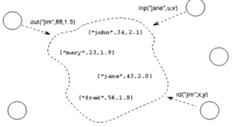
An element can be updated before deleting it and then reinserting the modified version. The out(Tuple) operation provides a key and the value of the arguments of the new tuple, while the other four operations specify the key and the arity (number of arguments) of the tuple to be read or consume. You can have duplicated tuples, so read or consumed tuples are not necessarily uniquely determined by provided key and arity. The operations rdp(TupleTemplate) and inp(TupleTemplate) guarantee to find a tuple that matchs with the request if this tuple has been inserted (but not consumed yet) in the space of tuples before the request was generated. In the Picture 1 you can see an example of a space of tuples in action [21].
1.2.3
Limitations of Tuple Spaces
One of the biggest advantages of the tuple spaces based interaction is that coordination is information driven: agents synchronize themselves; they also cooperate and enter into competition depending on the information available in a shared data space, so agents access it in associative mode by producing, reading or consuming information.
All this makes interaction protocols simple and expressive, but there is a problem: there is no way to separate how information is represented by how the informations are perceived by the agents (e.g. Dining Philosophers Problem, [3]).
CHAPTER 1. BACKGROUND KNOWLEDGE 7
Figure 1.1: Example of use of a tuple space.
1.2.4
From Tuple Spaces to Tuple Centres
The limits described in the previous subsection can be overcome by main-taining separated information’s representation from its perception in the agents communication space.
This result can be achieved by keeping the standard interface of tuple spaces and enriching it with the ability to define the behavior in terms of state transitions as a result of certain communication events.
This is the motivation that led to the Tuple Centres definition, which are tuple spaces whose behavior can be modeled in response to incoming or outcoming communication events, in accordance with the coordination requests specifications [12].
In this context, the Tuple Centres represent abstractions of general-purpose coordination, which can be understood as the interaction-oriented
8 CHAPTER 1. BACKGROUND KNOWLEDGE virtual machines to use as a base to build any kind of high-level abstraction for coordination between the components of a system.
1.2.5
Tuple Centre Definition
The Tuple Centre takes the concept of tuple space, specialize and extend it with a specific behavior which defines the behavior of the centers of tuples in response to incoming or outgoing communication events. The Tuple Centre’s behavior specification is expressed through a specific Turing equivalent language [13] to define reactions (a series of activities to be performed) that can be associated with any communication event which can be present in the Tuple Centre. This allows to define any coordination law by modelling the agents’s interaction space.
This language should allow:
• to define sets of operations (reactions) to run on a Tuple Centre • to associate reactions to any incoming and outgoing communication
events that may arise in the Tuple Centre
Each reaction can change the status of the center of tuples, such as inserting or consuming tuples, or access information related to the communication event that has triggered the reaction, such as the agent involved or the type of operation performed, etc. In this way you can model the Tuple Centre behavior as a simple primitives’ result, in order to shape the Tuple Centre’s semantics according to necessity.
Each event can trigger many reactions that will be performed before serving another communication event request by another agent; in this way, from the agent’s point of view, the result of a communication primitive exe-cuted on a Tuple Centre is the sum of the primitives and of all the reactions that it triggers, and this result is perceived as a single state transition in the Tuple Centre. So, we can say that a center of tuple with an empty behaviour specification set is reduced to a simple space of tuples.
Thus, the Tuple Centres are a means for data-driven communicating, that keep all advantages resulting from it, and also provides some of the characteristics of control driven models, such as the complete observability of communication events, the ability to react in a selective manner to them, and implement coordination rules by manipulating the interaction space
CHAPTER 1. BACKGROUND KNOWLEDGE 9 [12]. While the basic model of the Tuple Centre is not tied to any specific language, to define the behavior in terms of reactions (or defining a set of specification tuples) TuCSoN adopts a specific language called ReSpecT [22].
1.3
Model, language, architecture and
tech-nology in TuCSoN
TuCSoN (Tuple Centres Spread over the Network ) is a model for the co-ordination of distributed processes, as well as autonomous, intelligent and mobile agents [14].
The TuCSoN Tuple Centres adopt the ReSpecT language to define their behavior in terms of reactions (ie to define the set of specification tuples) [22].
1.3.1
TuCSoN Model
The TuCSoN ’s base entities are:
• TuCSoN Agents: the coordinables entities
• ReSpecT Tuple Centres: the means of coordination (by default in TuCSoN model) [15]
• TuCSoN Nodes: represent the topological abstraction that host the Tuple Centres
All agents, nodes and Tuple Centres have an universal identificator in a TuCSoN system.
Being agents proactive entities while Tuple Centres are reactive entities, the coordinated entities require coordination operations in order to act on the means of coordination: these operations are given by the TuCSoN co-ordination language. The agents interact by exchanging tuples through Tuple Centres using the TuCSoN coordination primitives that all together define the coordination language. The Tuple Centres provide two distinct tuple spaces:
10 CHAPTER 1. BACKGROUND KNOWLEDGE • the space to programming the behaviour of the tuple based
coordina-tion (specificacoordina-tion tuples)
The TuCSoN model has the following characteristics [23]:
• agents and Tuple Centres are distributed over the network • Tuple Centre belong to nodes
• agents can reside anywhere on the network, and thay can interact with the centers of tuples hosted by any reachable TuCSoN node.
• agents can move regardless of the device where they are running [16] • The Tuple Centres are associated in a permanent manner to a device,
possibly mobile (the mobility of the Tuple Centres depends on the device on which they reside).
So, a TuCSoN system is a collection of TuCSoN nodes possibly distributed and they are associated with agents in execution on mobile devices that interact with Tuple Centres on the nodes.
1.3.2
Naming in TuCSoN
Each TuCSoN node in a TuCSoN system is uniquely identified by the pair [NetworkID, PortNumber ]
Where the parameters in the pair are described as follows:
• NetworkID : this is the IP address, or DNS address, of the device that hosts the TuCSoN node
• PortNumber : this is the port number where the TuCSoN coordination service listen the coordination operation invocations
So, the abstract syntax of a TuCSoN node ID hosted by a device connected to the netword netid on the port with number portno is:
CHAPTER 1. BACKGROUND KNOWLEDGE 11 An admissible name for a Tuple Centre is any logical ground (that doesn’t contains variables) term of the first order. Each node contains at most one center of tuples for each admissible name, then each Tuple Centre is uniquely identified by its name associated with the admissible identifier of the node.
So, the TuCSoN complete name of a Tuple Centre tname in a TuCSoN node [networkid : portno] is:
[tname @ networkid : portno]
This works as a global identifier for a Tuple Centre in a TuCSoN system. An admissible name for an agent is any ground (that doesn’t con-tains variables) term of the first logic order [17]. When an agent enters into a TuCSoN system, this system assigne an universally unique identifier (Universally Unique Identifier - UUID [24]) to that agent.
So, the complete name agname for an agent who has been assigned the UUID uuid turns out to be:
[aname : uuid]
1.3.3
TuCSoN Language
The TuCSoN coordination language allows agents to interact with Tuple Centres by performing coordination operations. TuCSoN provides to coor-dinated entities many coordination primitives that allows agents to write, read and consume tuples in tuple spaces, and to synchronize with them.
The coordination operations are built starting from the coordination primitives and communication languages [23] :
• the tuples language
• the tuple templates language
Both languages depend from the kind of Tuple Centre adopted by TuCSoN , in fact the default means of coordination in TuCSoN are ReSpecT Tuple Centres and the language of the tuples and tuple templates are both logic based. More precisely:
12 CHAPTER 1. BACKGROUND KNOWLEDGE • each Prolog Atom can be an admissible TuCSoN tuple template As a result, TuCSoN default languages about tuples and tuple templates concide.
A TuCSoN coordination operation is invoked by a source agent on a determined destination Tuple Centre, which is in charge of its execution.
Each TuCSoN operation has two phaases:
• invocation: the source agent request to the destination Tuple Centre, the request transport all the informations about the invocation • completion: the reply from the Tuple Centre destination to the
source agent, the response includes all the informations about the execution
The abstract syntax of a coordination operation op invoked on the destina-tion Tuple Centre who has the complete name tcid is:
[tcid ? op]
Given the structure of a complete name for a Tuple Centre, the general abstract syntax for a coordination operation TuCSoN will be:
[tname @ netid : portno ? op]
Finally, the TuCSoN coordination language provides all the coordination primitives (eg: basic coordination primitives [20], bulk coordination primi-tives [18], uniform coordination primiprimi-tives [23]) needed to build coordina-tion operacoordina-tions.
1.3.4
TuCSoN Architecture
A TuCSoN system is characterized by a collection of TuCSoN nodes (possibly distributed) on which it is running a TuCSoN service.
A TuCSoN node is characterized by a device connected to the network on which it is running the service, and a network port where the TuCSoN service is listening for incoming requests. In principle, many TuCSoN nodes can running on the same device connected to the network, each of which is listening on a different port [23].
The TuCSoN default port number is 20504. Thus, as seen above, an agent can invoke operations by issuing the following request:
CHAPTER 1. BACKGROUND KNOWLEDGE 13 [tname @ netid ? op]
without specifying the port number portno, it means that the agent wishes to invoke the operation op on the Tuple Centre tname of the default node netid hosted by the device connected to the network netid on port 20504.
In principle, any other port can be used for a TuCSoN node. The fact that a TuCSoN node is available on a device connected to the network does not imply that a node is also available in the same unit on the default port (in practice, it is no certain that there is the default node).
Given an acceptable name for a Tuple Centre tname, the Tuple Cen-tre tname is an admissible Tuple CenCen-tre. The coordination space of a TuCSoN node is defined as a collection that contains all admissible Tuple Centres. Each TuCSoN node provides to agents a complete coordination space, so any coordination operation can be invoked on any admissible Tu-ple Centre belonging to any TuCSoN node.
Each TuCSoN node defines a default Tuple Centre, that reply to all the invocations received by any node of any operation that does not specify the destination Tuple Centre: the default Tuple Centre for each TuCSoN node is called default. As result, agents can invoke operation by the following request form:
[@ netid : portno ? op]
without specifying the Tuple Centre tname, it means wishing to make the operation op on the default Tuple Centre node netids hosted by the device connected to the network netid on the port portno.
Combining the concepts of default Tuple Centre and default port, agents can also invoke operations of the following request form:
[@ netid ? op]
with the meaning intending to invoke the operation op on the default Tuple Centre node netid hosted by the device connected to the network netid on the port 20504.
1.3.5
TuCSoN Coordination Space
The TuCSoN global coordination space is defined at any time from the collection of all available Tuple Centres on the network, and hosted by
14 CHAPTER 1. BACKGROUND KNOWLEDGE an identified node by their full name [23]. A TuCSoN agent running on any device connected to the network has at each instant the full TuCSoN global coordination space available for its coordination operations through invocations by the following form:
[tname @ netid : portno ? op]
that invoke the operation op on the Tuple Centre tname provided by the node netid on the port portno.
Given a device connected to the network netid that hosts one or more TuCSoN nodes, the TuCSoN local coordination space is defined at any time from the collection of all Tuple Centre made available by all TuCSoN nodes hosted by netid By exploiting the concepts of default node and default Tuple Centre, any agent can exploit the local coordination space for all request forms previously seen or any admissible request invocation [23].
1.3.6
TuCSoN Technology
TuCSoN is a Java and Prolog based middleware. TuCSoN relies on Java tuProlog for:
• first order logic tuples
• analyze and identify primitives
• ReSpecT specification language and virtual machine The TuCSoN middleware provides:
• Java APIs in order to exend Java programs with TuCSoN primitives • Java Classes in order to program TuCSoN agents with Java language • Prolog Libreries in order to exends tuProlog programs with TuCSoN
coordination primitives
Given any network-connected device that is running on a Java virtual machine (JVM), on it you can start a TuCSoN node to provide a TuCSoN service. The service on the node must:
• listen to the invocations of operations on the incoming port associated with the device TuCSoN service
CHAPTER 1. BACKGROUND KNOWLEDGE 15 • send received invocations to the destination Tuple Centres
• return operations’ completions
A TuCSoN service running on a node provides the full coordination space. The centers of tuples in a node can be in every moment actual or poten-tial :
• actual Tuple Centres: eligible Tuple Centres that already have a reification as an abstraction at runtime
• potential Tuple Centres: eligible Tuple Centres that have not yet as a reification abstraction at run-time
The service on the node have to change potentials Tuple Centres to actuals as soon as the first operation on them is received and served.
Details for using the TuCSoN infrastructure, both to initialize the ser-vice agents to handle Java and Prolog or to take informations about tools provided by TuCSoN package, can be found in the guide [23].
16 CHAPTER 1. BACKGROUND KNOWLEDGE
1.4
Background Knowledge for Cassandra
In this section will be described all background knowledge in order to un-derstand Cassandra .
Cassandra will be used in the module’s model in order to give a tech-nological solution to data storage issues that will be studied in following chapter.
1.4.1
CAP Theorem
A distributed system cannot simultaneously provide more than two out of the following three guarantees:
• Consistency • Availability
• Partition Tolerance
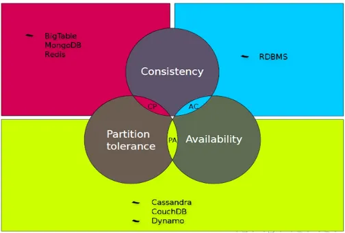
In the following picture will be described the previous property about distributed systems relating to following four important data storage dis-tributed system:
• Big Table - MongoDB Redis: management system of non-relational databases, document-oriented, type NoSQL [25]
• RDBMS : database management system (DBMS) that is based on the relational model, the full description is Relational DataBase Man-agement System [28]
• Cassandra : non-relational database management system optimized for handling large amounts of data; it will be described in following sections [27]
• Dynamo: fast, fully managed NoSQL database service that makes it simple and cost-effective to store and retrieve any amount of data, and serve any level of request traffic [26]
CHAPTER 1. BACKGROUND KNOWLEDGE 17 So, starting from these described distributed system, the graph that explain better the main property is:
Figure 1.2: Table Data about Distributed Systems Properties.
As you can see in the above picture, there are three possibility about the distributed system properties pair:
• CP: pair that explain that the distributed system has the consis-tency and partition tolerance properties
• AC: pair that explain that the distributed system has the availability and consistency properties
• PA: pair that explain that the distributed system has the partition tolerance and availability properties
To understand and interpret this theorem you have to undestand what are partitions. In a distributed system partitions are unavoidable.
Then you have to think to CAP as the following logic equation: P = ( A XOR C)
18 CHAPTER 1. BACKGROUND KNOWLEDGE So, as you can see in the previous logic equation, as a partition occurs, the tradeoff is between:
• A - availability: in terms of cost of inconsistency • C - consistency: in terms of cost of downtime
1.4.2
Variation over CAP Theorem
A better classification for real-life systems have been introduced with a variation over the CAP Theorem seen in the previous section.
This variation is based on the following condition: if there’s no partition, the tradeoff is about how much Latency the system employs to achieve a certain degree of Consistency.
Then, there is a logic equation better that the previous one and it is: P ? ( (A OR C) : (L OR C))
So, as you can see in this logic equation, there are two cases, dependently from the presence of a partition, in the case of one partition, the tradeoff is between Availability (A) and Consistency (C), while if there is no partitions (so in otherwise cases), the tradeoff is between Latency (L) and Consistency (C).
Starting from this variation about the seen theorem, there is a further system classification, in fact you have the following policy:
Systems following P ? C depend on :C So there is the following classification:
• [P ? C : C] : reliable systems (eg: DBMS) so this classification relating to fully ACID systems and traditional RDBMS
• [P ? A : C] : systems that give up on Consistency as partitions occur
• [P ? A : L] : high availability systems focused on low latency and high scalability
The ACID property is related to a group of four properties that an operation can have and the meaning is:
CHAPTER 1. BACKGROUND KNOWLEDGE 19 • A - atomic: operation that doesn’t break indivisible consistency (”all
or nothing”)
• C - consistent: committed updates don’t break domain constraints • I - isolated: doesn’t break serializable consistency
• D - durable: committed updates are persistent
These properties are the same about the transaction operation in the DataBase space because this section is related to systems that use database and similar structures in order to storage data. There are also three property that a system can have, relating to all properties previously seen; these properties are:
• Basic Availability: availability is the main focus of the system • Soft State: state of the system can change anytime, even without
inputs
• Eventually Consistent : system will become consistent after a long enough timeframe without inputs
These properties are derived by all previously seen properties and condi-tions and these are very important in order to obtain a better data storage distributed system as we want to have in the module studied in the following chapter.
1.4.3
Limits of RDBMS
The main limits of RDBMS are related to the Two Phase Commit algorithm that put in evidence all limits and problems derived by most system characteristics, like for example the huge quantity of data to storage. In particular, will be explained all properties about the Two Phase Commit and will be described all problem and all its limits because this is the most used algorithm in RDBMS.
The Two Phase Commit is an algorithm taking place in a Distributed Atomic Transaction (DAT ). This algorithm has the aim to coordinate all processes that participates in a DAT. This algortithm is a type of Consensus
20 CHAPTER 1. BACKGROUND KNOWLEDGE Protocol in order to achieve the described aim and it tolerates a wide fraction of failure configurations about participant processes.
The Two Phase Commit is composed by two phases:
• Phase 1 - Commit Request Phase : the Coordinator sends a query to commit to each Participant of the transaction and waits for all replies; each Participant performs the transaction up to the point in wich it’s asked to commit and send a reply, this reply can be a message of:
– Agreement : which means that the Participant would commit the transaction
– Abort : which means that the Participant would roolback the transaction
• Phase 2 - Commit / Rollback phase : the Coordinator decides wheter to commit or rollback the transaction, and issues the outcome to each Participant ; each Participant follows the issued commit or roll-back, releasing lock and resources; in the end, each Participant sends an acknowledgement back to the Coordinator. The Coordinator com-pletes the transaction when all acknowledgements have been received From this description it can be seen the Consistency costs a lot because • it block the execution in many parts of each phase
• the Coordinator is a Single Point of Failure • Horizontal Scaling is not so effective
All solutions in the RDBMS world are related to optimizations about the recursive approach (2PC optimizations like Recursive 2PC, etc.) or a variation of a known algorithm (for example the Three Phase Commit that’s more resilient to failures but still blocking).
So, it’s evident that in some scenarios the ACID is too much for this kind of DBMS and it needs to introduce a new architectural model that have to be more efficient and more powerfull in actual scenarios.
CHAPTER 1. BACKGROUND KNOWLEDGE 21
1.5
Cassandra
In this section will be described Cassandra , a non-relational database man-agement system optimized for handling large amounts of data that can work in a distributed management system maintaining all its features [27].
A particular feature about this DBMS is that Cassandra ’s Data Model is based on Google’s Bigtable and its Distribution Model is based on Amazon’s Dynamo. This is a very important feature because from these model derive all the following key properties about Cassandra : • NoSQL Data Model : deriving from Google’s Bigtable this model doesn’t adopt SQL Data Model so its data model can be seen as a multidimensional hash-map that have to contain all system’s data • Decentralized Model : deriving from Amazon’s Dynamo this
DBMS Model is optimized as a distributed system where nodes are peers, each node can satisfy any request and there is no single-point of failure
• Elastic Scalability : from two ”parents system” derive also this property that give to the system the horizontally scalability, both up and down, almost linearly
• Fault Tolerance : thanks to the mix of those two system model, this property is giveng by data replication that allows to add and replace any node without downtime
• High Availability : given from the reliability of this model and its elastic runtime adapting to any distributed configuration given by deriving from Amazon’s Dynamo
• Tuneable Consistency : in order to obtain the best kind of consis-tency, this property ca be given by two diffent ways:
– by cluster configuration: working on many distribution factors (eg replication factor)
– by client, per-operation: working on many model levels basing the choice on many requirements and issues (eg consistency level)
22 CHAPTER 1. BACKGROUND KNOWLEDGE
1.5.1
Data Model
As previously seen, the Cassandra ’s Data Model derive from Google’s Bigtable so it has almost all features about that model [29].
The most important entities in the Cassandra ’s Data Model are: • Keyspace: outermost container for data, it is similar to the table
schema in Relational DataBase (RDB ) world
• Column Family: collection of columns, it is similar to table in Re-lational DataBase (RDB ) world
• Column: map from row keys to values; values updates are times-tamped and all timestamps are provided by clients that communicate with the system
• SuperColumn: special kind of columns wich hold normal columns; this special columns can have also special functions about data ma-nipolation
There are also many characters to underline because these characters make this model better thant many others; these characters are related to the schema, to amount of data and to the sorting about data.
In the firse case you have that different rows can have different columns in the same Column Family, this character allow to define this model’s schema as a schema-less ”tables”, so it give to this schema many advantages relating to constrains about columns and their families. In the second case you have that the data growth is often in the ”column direction” while in the RDB world the data growth is related in the ”rows direction”. The last key character about this schema is related to the sorting of data, in fact, in this schema columns are sorted by their name that make more efficient all column-slice queries and it is heavily exploited in data design.
In the end, this data model is classified as JSON-ified because all en-tities and features are represented and decoded by using the JSON lan-guage because this lanlan-guage has many important features and advantages in network communication in order to obtain a better efficency and a better reliability in the distributed data storage system.
CHAPTER 1. BACKGROUND KNOWLEDGE 23
1.5.2
Data Distribution Model
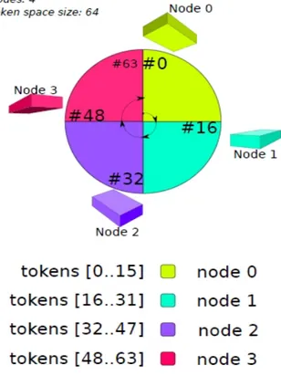
As previously seen, the Cassandra ’s Distribution Model derive from Amazon’s Dynamo so it has almost all features about that model [26]. This model’s Data Space is represented as a ring of tokens (this number depends on the distributed system) where each token cooresponds to a row key. This Data Space is sliced into ranges, where the number of ranges is equal to the number of nodes, so there is a binary correspondance between nodes and ranges. Thanks to that feature, each node covers a slice of the token space and the mapping operation between row keys and tokens is the aim of a component called Partitioner; consequently this mapping affects data distribution among the nodes.
Figure 1.3: Example of Cassandra’s Data Distribution Model.
This distribution model is based on the Row Oriented Sharding and Replication of Data that allows many important functionalities in order
24 CHAPTER 1. BACKGROUND KNOWLEDGE to manipolate the Data Space.
In the end there are the following main knobs relating to the possible configurations:
• cluster-wide configuration: in this configuration the Partitioner controls how data is partitioned (for example: which node belongs k-row key?)
• per-keyspace configuration: in this configuration the Replication Factor controls how many replicas are stored and the Replication Strategy controls in which nodes replicated data goes
1.5.3
Client Requests
First of all, if a client has to send a request to a node, it needs to connect to the target node and after that operation, the client can perform the request. The node plays the Coordinator role for this operation because the mes-sage exchanging between these two entities will be managed by the entity that have to sadisfy the request (the node).
Then, the node acts to fullfill the received request and notify the result to the sender client if the request have been executed correctly or not. In all these phases, the communication to other nodes is generally involved.
Each client request has an associated Consistency Level: the minimum number of replicas that should respond. These levels are described for read and write operations in the following table.
CHAPTER 1. BACKGROUND KNOWLEDGE 25 From the above picture you can see that the write operation has following properties about its executions and the consistency level:
• the consistency level to ALL or QUORUM guarantee writes to a suf-ficient number of replicas
• QUORUM statistically has a lower latency then others and is more fault tolerant then ALL
• failed writes don’t cause roll-backs in any of the eventual nodes where the write succeeded
• Cassandra guarantees atomic writes on a single node, row key basis There is a particular situation when the Coordinator detects that a replica node for the write operation is down and this write operation is set to the ANY or higher consistency level. In this situation the Coordi-nator writes down an hint for that operation that will be handoff to the target node once it will become available again.
This operation is called Hinted Handoff and is executed because it reduce the time required for a temporarily failed node to become consistent again and provides extreme write Availability when Consistency is not required (Consistency Level ANY).
Like any other operation, this one has some important issues to consider: • When a failed node becomes available again, could be flooded by hints
from other nodes?
• It’s possible to disable Hinted Handoff or reduce its priority of over ”normal” writes?
In order to obtain an efficient Hinted Handoff operation you have to consider these issues basing on requirements and use case.
26 CHAPTER 1. BACKGROUND KNOWLEDGE Like write operations there are many issues related to read operations that can be done. In this phase the Coordinator contacts only a number of replicas specified by the Consistency Level basing on the number of replicas involved in that process, in fact:
• only one replica involed: a background thread performs Read Repair operation to ensure Consistency with other replicas
• more then one replicas involed: if the involved replicas are incon-sistent, a foreground (blocking) Read Repair is performed, a back-ground thread performs Read Repair between all replicas and is return the most recent value
The Read Repair is a timestamp-based way to achieve replica concil-iation, as seen above, these timestamp are provided by clients and, because they are part of the system, they must have low clock drifts (for example this issue is solved by using vector clocks like in Dynamo [26]).
In the end, we have to answer to an important question: Where to put latency?
For this issue Cassandra choose low latency writes over low latency reads (Read Repair over Write Repair). The adopted model is the Cache write-back model (Borrowed from BigTable [25]) where:
• writes are written to a commit log
• writes are written to in-memory tables (memtables)
• writes are flushed in persistent storage to read-only tables (SSTables: Sorted Strings Tables) that are periodically optimized.
So, the Consistency can be:
• Weak: when you have that (Write + Read) is lesser then Replica-tion Factor, in this case clients may read stale values
• Strong: when you have that (Write + Read) is greather then Repli-cation Factor, in this case clients will always read the most recent write
CHAPTER 1. BACKGROUND KNOWLEDGE 27 In the following pictures is showed an example of Strong Consistency and the impact of the Consistency Level Choice on the system.
Figure 1.5: Strong Consistency Example.
Figure 1.6: Impact of the Consistency Level Choice.
All details about model and implementation of Cassandra can be found in its website [27] like the other system seen in this chapter (Google’s Bigtable [?] and Amazon’s Dynamo [26]).
Chapter 2
JADE
2.1
What is JADE
JADE (Java Agent DEvelopment Framework) [30] is a Java-based framework to develop agent-based applications in compliance with the FIPA specifications [31] for interoperable, intelligent, multi-agent systems.
As an agent-oriented middleware, JADE pursues the twofold goal of being:
• a full-fledged FIPA-compliant agent platform. Hence, it takes in charge all application-independent aspects (for example agents life-cycle management, communications, distribution transparency, etc.) needed to implement a MAS [32]
• a simple comprehensive agent development framework. Therefore it provides Java developers a set of APIs (it stands for Application Programming Interface, so all interfaces needed to developers) to build their own customizations
Being fully implemented in Java, JADE is a notable example of a dis-tributed, object-based and agent-oriented infrastructure, hence an interesting example about how to face a design/programming paradigm shift. Being compliant to FIPA standards, JADE is a complete and coher-ent agcoher-ent platform providing all the necessary facility to deploy MASs.
30 CHAPTER 2. JADE As follows all main features about JADE are itemized, in fact, JADE offers:
• a distributed agent platform, where distributed means that a single JADE system can be split among different networked hosts
• transparent, distributed message passing interface & service • transparent, distributed naming service
• white pages & yellow pages discovering facilities
• intra-platform agent mobility (contex, to some extent) • debugging & monitoring facilities
All other details about JADE and FIPA can be found at the specific websites: JADE Official Website [30] and the FIPA Official Website [31]
2.2
JADE Architecture
The following picture represents the main JADE architectural ele-ments.
An application based on JADE is made of a set of components (the Agents) each one having a unique name. Agents execute tasks and interact by exchanging messages.
Agents live on top of a Platform that provides them with basic ser-vices such as message delivery. A Platform is composed of one or more Containers each one can be executed on different hosts thus achieving a distributed platform and each Container can contain zero or more Agents.
For instance, with reference to the picture below, Container Container 1 in host Host 3 contains Agents A2 and A3. Even if in some particular scenarios this is not always the case, you can think of a Container as a JVM (it stands for Java Virtual Machine, the virtual machine that execute the Java Platform) so there is the relation:
CHAPTER 2. JADE 31 A special Container is the Main Container existing in any platform. The Main Container is itself a container and can therefore contain agents, but differs from other containers as:
• It must be the first container to start in the platform and all other containers register to it at bootstrap time
• It includes two Special Agents:
– the AMS (it stands for Agent Management System) that rep-resents the authority in the platform and is the only agent able to perform platform management actions such as starting and killing agents or shutting down the whole platform (normal agents can request such actions to the AMS)
– the DF (it stands for Directory Facilitator ) that provides the Yellow Pages Service where agents can publish the services they provide and find other agents providing the services they need
It should be noticed that if another Main Container is started, as in host Host 4 in the following picture, this constitutes a new platform.
All details about this architecture will be described in following sections.
2.2.1
JADE & FIPA
According to FIPA, the Agent Platform can be splitted on several hosts given that:
• each host acts a container of agents, that is, provides a complete runtime environment for JADE agents execution (for example the lifecycle management, message passing facilities, etc.)
• (at least) one of these containers is the main container (actually, the first started ), responsible to maintain a registry of all containers in the same JADE platform (through wich agents can discover each other )
• hence, it promotes a P2P (it stands for Peer to Peer, the complete description can be found at the specific Wikipedia web page [33]) interpretation of a MAS
32 CHAPTER 2. JADE
Figure 2.1: JADE Architectural Model
Then, after the Agent Platform description, we introduce the JADE AMS, that is another particular part of a JADE system. So, for a given JADE platform, a single AMS exists, wich:
• keeps track of all agents in the same JADE platform, even those living in remote containers
• should be contacted by JADE agents prior to any other action (they do not exist until registered by an AMS)
• hence, provides the White Pages Service, that is a location-transparent naming service
Another JADE foundamental components is the DF (it stands for Di-rectory Facilitator); a singleton DF exists for each JADE platform, that: • keeps track of all advertised services provided by all agents in the same
CHAPTER 2. JADE 33 • should be contacted by JADE agents who wish to publish their
capa-bilities
• hence, provides the default Yellow Pages Service, according to the publish & subscribe paradigm
The last JADE foundamental component is the ACC (it stands for Agent Communication Channel) that is the agent that provides the path for basic contact between agents inside and outside the platform; so it is the default communication method which offers a reliable, ordered and accurate message routine service and it must also support all functions for interoperability between different agent platforms.
So, for a given JADE platform, a distributed message passing sys-tem exists, which is the ACC:
• it controls all exchange of messages within the JADE platform, be them local or remote
• it implements all the needed facilities to provide asynchronicity of communications
• it manages all aspects regarding FIPA ACL (it stands for FIPA Agent Communication Language) message format, such as se-rialization and desese-rialization
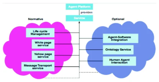
In the end, the JADE FIPA Architecture is showed in the following picture, that contains the normative and optionals services given by the FIPA required services.
2.2.2
JADE Agents
Being JADE an object-based middleware, JADE agents are first of all Java objects:
• user-defined agents must extend the specific Java class, thus inheriting some ready-to-use method
• a JADE agent is executed by a single Java thread (there is an ex-ception, though)
34 CHAPTER 2. JADE
Figure 2.2: FIPA required services
JADE agents have a wide range of features enabling their autonomy, despite being still Java objects, so:
• all JADE agents must have a globally unique name (defined as aid), which is, by default, the concatenation by simbol @ of their local name and the JADE platform name
• agents bussiness logic must be expressed in terms of behaviours • JADE agents can communicate by exchanging FIPA ACL
mes-sages
Thus, according to FIPA, a JADE agent can be in one of several states during its lifetime:
• Initiated: the agent object has been built, but cannot do anything since it is not registered to the AMS yet, so it has no aid even • Active: the agent is registered to the AMS and can access all
JADE features, in particular, it is executing its behaviours
• Waiting: the agent is blocked, waiting for something to happen and to react to, tipically this is an ACL message
CHAPTER 2. JADE 35 • Suspended: the agent is stopped, therefore none of its behaviours
are being executed
• Transit: the agent has started a migration process and it will stay in this state until migration ends
• Unknown: the agent is dead, so it has been deregistered to the AMS Thus, the lifecycle of a JADE agent can be described as the following picture, where are described all states and transitions of an agent’s state, according to the FIPA.
So, as follows, is showed the FIPA Agent Platform Life Cycle:
Figure 2.3: FIPA Agent Platform Life Cycle
After the agent lifecycle’s description, we will treat the description about the agent behaviours description in order to explain all details about
36 CHAPTER 2. JADE these entities. By definition, JADE agents are autonomous entities, therefore they should act independently and in parallel with each other, so the need for efficency drives toward the execution of JADE agents as a single Java thread each but, however, agents need to perform complex activities, possibly composed by multiple tasks, even concurrently.
Thus, theis contrasting needs to behaviours in order to conciliate them. A behaviour can be seen as an activity to perform with the goal of completing a task. It can be represented both as a proactive activity started by the agent on its own, as well as a reactive activity performed in response to some event (for example in response to a timeout event, messages event or any other event relating to agents).
However, JADE implements behaviours as Java objects, which are executed concurrently (still by a single Java thread ) using a non-preemptive, round-robin scheduler that is internal to the agent class but hidden to the developer.
Thus, the JADE multi-tasking, non-preemptive scheduling policy is described as showed in the following picture:
CHAPTER 2. JADE 37
2.2.3
FIPA ACC
According to the FIPA specification, JADE agents communicate via asyn-chronous message passing where:
• each agent has a message queue (a sort of mailbox ) where the JADE ACC delivers ACL messages sent by other agents
• whenever a new entry is added to the mailbox, the receiving agent is notified so, it does not need to block nor to poll either
These specifications about the message passing are valid and must be respected when the agent actually process a message is up to the agent itself (or the programmer), for the sake of agents autonomy
Thus, the ACL compliant messages have a crucial role in order to obtain the situation where each agent is able to understand each other. So, they need to have a defined format and semantic relating to messages.
Hence, an ACL message contains the following foundamental informa-tions:
• sender: the agent who sends the message; this field is automatically set by the middleware component where the sender agent live
• receiver: the agent who the message targets; this field is setted by the sender agent because it may be many different target agents • performative: the name of the communication act the agents want
to carry out ; this field is constrained by a FIPA ontology • content: the actual information conveyed by the message • language: the syntax used to encode to the content • ontology: the semantics upon which the content relies
Logically, there are many other fields but they depend on the technology progress of JADE so, the itemized fields are the foundamental fields that must be present in all JADE versions.
38 CHAPTER 2. JADE After the previous description about the FIPA communication model, the following picture shows a model abstraction about it in order to repre-sent all itemized foundamental fields about a message and its communica-tion.
Figure 2.5: FIPA communication model abstraction
In the end, JADE agents have a couple of methods in order to guarantee a stable interaction mode; these foundamental communication primitives are:
• send: to send a message to a implicity specified recipient agent • receive: to asynchronously retrieve the first message in the mailbox,
logically, if the mailbox contains only one message, this message will be retrieved to the target agent involved in the communication • timed receive: to perform a timed, synchronously receive on the
mailbox in order to obtain the situation where the timeout causes agent to wake up, so it has to retrieve the messages contained in the mailbox
CHAPTER 2. JADE 39 • selective receive: to retrieve a message from the mailbox which matches a given message template, so the message queue order is by-passed by the target agent involved in the communication because it selects the message to retrieve
All these methods are distribution-transparent, that is they choose the proper address and transport mechanism based upon sender and receiver locations in order to obtain the best communication situation.
Chapter 3
Naming, Locator & Research
Service
Structure & Interaction Model
In this chapter it will be introduced the general model for providing services related to naming, location and research service.
These services are part of a separate module that can be used with any middleware, less than small changes relative to the structural details of the application context of the middleware considered. In the case treated, this module is used with the middleware TuCSoN , introduced and described in the first chapter.
This model has been studied starting from the previously seen JADE system because that system is an efficient distributed middleware for dis-tributed system. This system is JADE like in terms of layer vertical mod-eling because it is a good solution relating to system network distribution. Comparing with the JADE system, this model’s characteristics have been increased in order to obtain a better model, in particular it has been studied in order to increase the characteristics about the network distribu-tion because, as described in the previous chapter, JADE has many con-strains that limit the possible network distribution of that system. In fact, this model is more distributed-oriented than JADE because all lower layers can be distributed excep the upper layer because, as you can see in the fol-lowing sections, it must be located on the consumer because it is the layer that has the aim to manage the communication with the consumer.
42
CHAPTER 3. NAMING, LOCATOR & RESEARCH SERVICE STRUCTURE & INTERACTION MODEL Another advantage of this model compared to jade is the complete in-dependence of the layers by their location in order to remove all the con-straints that made jade less network distribution-oriented of internal parts of the middleware, therefore this model has a higher efficiency in terms of computational load.
Also there is another foundament characteristic of this model: the inde-pendence of this module by the consumer middleware.
The decision to design this module as a separate module from the context of specific use (varying the model that will be introduced for TuCSoN the same logic can be adapted to any type of middleware) was taken to obtain the maximum orthogonality between the consumer middleware (TuCSoN in the considered case), and the service module introduced in this chapter. The orthogonality is guaranteed by the characteristic malleability of the structure of the considered module because this module template is suitable for multiple contexts of use.
As you will see below, this module can be contained entirely on the consumer, or may be distributed, in this case there will be only a part of the module of a consumer (probably would be on the consumer only the part of the module that it intends to use, or the module’s most used part) and the rest of the module would be placed in another point of the system and on demand from the consumer involved in the distributed architecture of that specific instance of the module.
3.1
Main Model
The following picture shows the architectural main model of the considered module. This model has been studied in order to have a common external interface to customers and three specialized modules inside:
• a module related to the Universal Naming Service: service that provides all functions about the naming system (for example: giving an universal identificator to a customer)
• a module related to the Universal Locator Service: service that provides all functions about the locator system (for example: register-ing the current customer’s position)
CHAPTER 3. NAMING, LOCATOR & RESEARCH SERVICE
STRUCTURE & INTERACTION MODEL 43 • a module related to the Research Service: service that provides all functions about the research system (for example: research the customer’s position starting from its universal identificator)
All these modules will be described in details in following sections.
Figure 3.1: Main Architectural Model
As described above, a consumer can contain only a part of the module (for example, if it uses most the location service then this part of the module will be local on the consumer while the other could be distributed), and in this case the module is distributed, or the consumer can contain the entire module, so without any system distribution. In any case, the consumer is coordinated by the individual services so you do not have problems with latency and fault tolerance.
44
CHAPTER 3. NAMING, LOCATOR & RESEARCH SERVICE STRUCTURE & INTERACTION MODEL
3.2
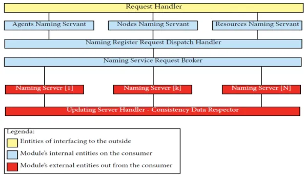
Naming Service Model
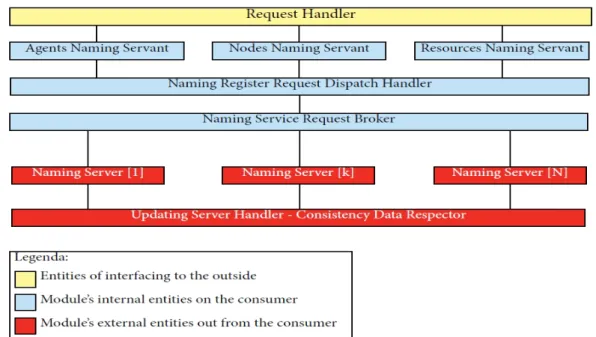
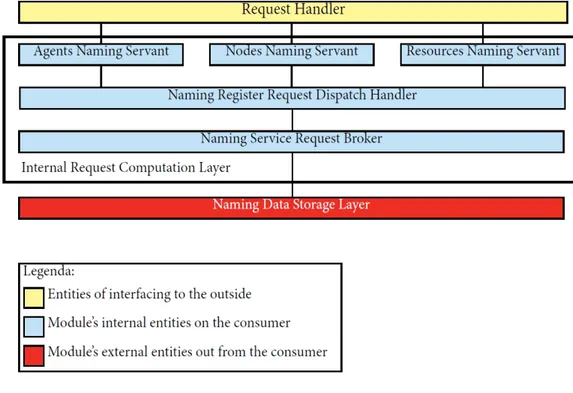
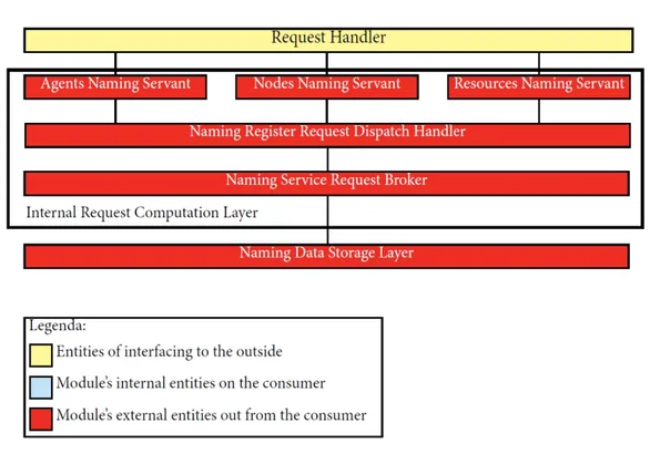
This module handles registrations and all claims relating to the naming system. As shown in the description in the following picture, also some components of this module’s part can be distributed, so there is a further distribution of the model, this further distribution will be further detailed later in this section.
The infrastructural model of this module is based on the three layer vertical modeling and in one of these layers there is a further horizontal subdivision in many layers as you can see in the picture below.
Figure 3.2: Naming Service Architectural Model
As seen in the picture there are the following three vertical layers: • outside interfacing layer : this layer interface the module with the
external consumer (for example the TuCSoN middleware)
• internal request computation layer : this layer is designed to compute the received requests from the above layer and return the results of