I
POLITECNICO DI MILANO
School of industrial and information engineering
Master of Science in Electrical Engineering
Thesis Topic: Batteries and Charging Method
Supervisor:
Prof. Brenna Morris
Author:
Noman Mohammad
Matr. 10421881
Academic year
2018-2019
II
Acknowledgement
I would like to thank Dr. Morris Brenna and his assistant Leone Carola for their support in this thesis process, because I’m also working and trying to do my best to complete my studies , I want to say thanks to my parents for supporting me in this long journey.
II
Abstract
Nowadays many devices are fed by batteries, especially li-ion based batteries. Some examples are like smartphones, smartwatches, laptops, electrical vehicles. And in this document, I will try to describe the type of battery used now and their application, the most promising technology is based on Li-ion battery, used in EVs, there will be a chapter on the batteries used in EVs and comparison between them. Obviously the best one is Li-ion based battery, charging and discharging of li-ion batteries is typically faster than the others.
What will be the future development of the batteries, the battery technology is top of the priority list for many players, the companies try to build a key position in the market.
I will describe the future development and what is needed to improve the lifetime of a battery and obviously they must assure the safety in every circumstance. Most important in EVs usage. The study will focus on silica anodes, advanced cathodes and solid-state electrolytes.
In the last one there is a little chapter on fast charging and the problems due to it, like the temperature and the lithium deposition.
III
Table of Content
Sommario
Acknowledgement ... I Abstract ... 3 Table of Content ... iv List of Tables ... 7 1 Introduction ... 1 1.1 THE CELL ... 2 1.2 ELECTRODES ... 2 1.3 ELECTROLYTE ... 31.1 Type of existing batteries and main application ... 4
1.1.1 Primary Batteries ... 4
1.1.2 Secondary Batteries ... 5
1.1.2.1 Lithium-ion Batteries ... 7
1.1.2.2 Nickel-Cadmium Batteries ... 8
1.1.2.3 Nickel-Metal Hydride Batteries ... 9
1.1.2.4 Lead-Acid Batteries ... 10
2 EV batteries (Li-ion) ... 11
2.1 Hybrid/Electric Vehicle Designs ... 12
2.2 Available Batteries for EV ... 15
2.2.1 Lead-acid battery ... 16
2.2.2 Nickel Metal Hydride Battery ... 19
2.2.3 Lithium-ion Battery ... 20
2.2.4 Lithium Polymer Battery ... 22
3 Future Developments ... 23
3.1 Challenges is Lithium-ion battery ... 25
3.2 Silica anodes ... 26
3.2.1 The solutions for Si anode practical application ... 27
3.2.2 Silicon-carbon anode ... 28
3.2.3 Vapor deposition ... 28
3.2.4 High temperature solid phase synthesis ... 28
3.2.5 Mechanical alloying ... 29
3.2.6 Electrostatic electrospinning ... 29
3.2.7 Modification of silicon–carbon anode materials ... 29
3.2.8 Structural modification of silicon–carbon anode materials ... 29
III
3.2.10 Silicon-carbon nanofibers ... 31
3.2.11 Silicon–carbon nanotubes ... 33
3.2.12 Silicon-carbon nanosphere ... 34
3.2.13 Doping modification of silicon–carbon anode materials ... 34
3.2.14 Si/nitrogen-doped carbon anode materials ... 34
3.2.15 Compound modification of silicon–carbon anode materials ... 35
3.2.16 Si/carbon/graphite anode materials ... 36
3.2.17 Si/carbon/graphene anode materials ... 36
3.2.18 Conclusion and perspective ... 37
3.3 Advanced cathodes ... 38
3.3.1 Challenges of Li-Ion and Li-S Battery Cathodes ... 38
3.3.2 Methods for Making 3D Porous Li-Ion Battery Cathodes ... 39
3.3.3 Sol-Gel Method ... 41
3.3.4 Methods for Constructing 3D Porous Li-S Battery Cathodes and Their Comparison ... 43
3.3.5 Brief Comparison between Li-Ion and Li-S Batteries ... 45
3.4 Solid-state electrolytes ... 45
3.4.1 Thin Film Solid State Batteries ... 46
3.4.1.2 Moving to 3D Architectures ... 48
3.4.1.3 Electrode Selection ... 49
3.4.2 The Fabrication of All-Solid-State Lithium-Ion Batteries via Spark Plasma Sintering ... 51
3.4.2.1 Materials and Methods ... 52
3.4.2.2 Results and Discussion ... 54
4 Problems which born from the fast charge ... 58
4.1 Li-ion battery Fast charging fundamentals ... 60
4.1.2 Li-ion battery fast charging techniques ... 60
4.2 Temperature ... 64
4.3 Lithium deposition ... 66
IV
List of Figures
Figure 1 ... 2 Figure 2 ... 2 Figure 3 ... 4 Figure 4 ... 5 Figure 5 ... 7 Figure 6 ... 8 Figure 7 ... 9 Figure 8 ... 10 Figure 9 ... 13 Figure 10 ... 13 Figure 11 ... 14 Figure 12 ... 14 Figure 13 ... 17 Figure 14 ... 17 Figure 15 ... 18 Figure 16 ... 18 Figure 17 ... 20 Figure 18 ... 21 Figure 19 ... 21 Figure 20 ... 25 Figure 21 ... 27 Figure 22 ... 27 Figure 23 ... 31 Figure 24 ... 32 Figure 25 ... 33 Figure 26 ... 34 Figure 27 ... 35 Figure 28 ... 36 Figure 29 ... 37 Figure 30 ... 40 Figure 31 ... 40 Figure 32 ... 46 Figure 33 ... 47 Figure 34 ... 52 Figure 35 ... 53 Figure 36 ... 55 Figure 37 ... 56 Figure 38 ... 57 Figure 39 ... 61 Figure 40 ... 62 Figure 41 ... 63 Figure 42 ... 67V
List of Tables
Table 1 ... 15 Table 2 ... 20 Table 3 ... 23 Table 4 ... 24 Table 5 ... 28 Table 6 ... 30 Table 7 ... 35 Table 8 ... 42 Table 9 ... 44 Table 10 ... 54 Table 11 ... 55 Table 12 ... 641
1 Introduction
The purpose of this chapter is to introduce and explain the basic theory and characteristics of batteries. The batteries which are discussed and illustrated have been selected as representative of many models and types which are used in many applications today. No attempt has been made to cover every type of battery in use, however, after completing this chapter you will have a good working knowledge of the batteries which are in general use.
A battery is a collection of one or more cells that go under chemical reactions to create the flow of electrons within a circuit. There is lot of research and advancement going on in battery technology, and as a result, breakthrough technologies are being experienced and used around the world currently. Batteries came into play due to the need to store generated electrical energy. As much as a good amount of energy was being generated, it was important to store the energy so it can be used when generation is down or when there is a need to power standalone devices which cannot be kept tethered to the supply from the mains. Here it should be noted that only DC can be stored in the batteries, AC current can’t be stored.
First, you will learn about the building block of all batteries, the Cell. We will explore the physical makeup of the cell and the methods used to combined cells to provide useful voltage, current and power, we will discuss also about the chemistry of the cell and ow chemical action is used to convert chemical energy to electrical energy.
Batteries are widely used as sources of direct-current electrical energy in automobiles, boats, aircraft, ships, portable electric/electronic equipment, and lighting equipment. In some instances, they are used as the only source of power; while in others, they are used as a secondary or standby power source. A battery consists of several cells assembled in a common container and connected together to function as a source of electrical power.
Battery cells are usually made up of three main components: 1.
The Anode (Negative electrode)
2.
The Cathode (Positive electrode)
3.The electrolytes
The anode is a negative electrode that produces electrons to the external circuit to which the battery is connected. When batteries are connected, an electron build up is initiated at the anode which causes a potential difference between the two electrodes. The electrons naturally then try to redistribute themselves, this is prevented by the electrolyte, so when an electrical circuit is connected, it provides a clear path for the electrons to move from the anode to the cathode thereby powering the circuit to which it is connected. Anode and cathode are separated by a porous barrier.
2
Figure 1
Figure 2
1.1 THE CELL
A cell is a device that transform chemical energy into electrical energy. The simplest cell known as either a galvanic or voltaic cell, is shown in figures 1-1. It consists of a piece of carbon (C) and a piece of Zinc (Zn) suspended in a jar that contains a solution of water (H2O) and sulfuric acid (H2SO4)
called the electrolyte.
Fig 1-1: Simple voltaic or galvanic cell.
The cell is the fundamental unit of the battery. A simple cell consists of two electrodes placed in a container that holds the electrolyte. In some cells the container acts as one of the electrodes and, in this case, is acted upon by the electrolyte.
1.2 ELECTRODES
The electrodes are the conductors by which the current leaves or return to the electrolyte. In the simple cell, they are carbon and zinc strips that are placed in the electrolyte; while in the dry cell (fig. 1-2), they are the carbon rode in the center and zinc container in which the cell is assembled.
3
1.3 ELECTROLYTE
The electrolyte is the solution that acts upon the electrodes. The electrolyte, which provides a path for electron flow, may be a salt, an acid, or an alkaline solution. In the simple galvanic cell, the electrolyte is in a liquid form. In the dry cell, the electrolyte is a paste.
CONTAINER
The container which may be constructed of one of many different materials provides a means of holding (containing) the electrolyte. The container is also used to mount the electrodes. In the voltaic cell the container must be constructed of a material that will not be acted upon by the electrolyte.
4
Figure 3
1.1 Type of existing batteries and main application
Batteries generally can be classified into different categories and types, ranging from chemical composition, size, form factor and use cases, but under all of these are two major battery types;
1. Primary Batteries 2. Secondary Batteries
A primary cell is one in which the chemical action eats away one of the electrodes, usually the negative electrode. When this happens, the electrode must be replaced, or the cell must be discarded. In the galvanic-type cell, the zinc electrode and the liquid electrolyte are usually replaced when this happens. In the case of the dry cell, it is usually cheaper to buy a new cell.
A secondary cell is one in which the electrodes and the electrolyte are altered by the chemical action that takes place when the cell delivers current. These cells may be restored to their original condition by forcing an electric current through them in the direction opposite to that of discharge. The automobile storage battery is a common example of the secondary cell.
1.1.1 Primary Batteries
Primary batteries are batteries that cannot be recharged once depleted. Primary batteries are made of electrochemical cells whose electrochemical reaction cannot be reversed. Primary batteries exist in different forms ranging from coin cells to AA batteries. They are commonly used in standalone applications where charging is impractical or impossible. A good example of which is in military grade devices and battery powered equipment. It will be impractical to use rechargeable batteries as recharging a battery will be the last thing in the mind of the soldiers. Primary batteries always have high specific energy and the systems in which they are used are always designed to consume low amount of power to enable the battery last if possible.
Fig 1-3: Primary Batteries
Some other examples of devices using primary batteries include; Pacemakers, Animal trackers, Wrist watches, remote controls and children toys to mention a few. The most popular type of primary batteries are alkaline batteries. They have a high specific energy and are environmentally friendly, cost-effective and do not leak even when fully discharged. They can be stored for several years, have a good safety record and can be carried on an aircraft without being subject to UN Transport and other regulations. The only downside to alkaline batteries is the low load current, which limits its use to devices with low current requirements like remote controls, flashlights and portable entertainment devices.
5
Figure 4
1.1.2 Secondary Batteries
Secondary batteries are batteries with electrochemical cells whose chemical reactions can be reversed by applying a certain voltage to the battery in the reversed direction. Also referred to as rechargeable batteries, secondary cells unlike primary cells can be recharged after the energy on the battery has been used up.
They are typically used in high drain applications and other scenarios where it will be either too expensive or impracticable to use single charge batteries. Small capacity secondary batteries are used to power portable electronic devices like mobile phones, and other gadgets and appliances while heavy-duty batteries are used in powering diverse electric vehicles and other high drain applications like load levelling in electricity generation. They are also used as standalone power sources alongside Inverters to supply electricity. Although the initial cost of acquiring rechargeable batteries is always a whole lot higher than that of primary batteries but they are the most cost-effective over the long-term.
A secondary cell or battery is one that can be electrically recharged after use to their original pre-discharge condition, by passing current through the circuit in the opposite direction to the current during discharge. The following graphic evidences the recharging process.
Secondary batteries fall into two sub-categories depending on their intended applications.
• Cells that are utilized as energy storage devices, delivering energy on demand. Such cells are typically connected to primary power sources to be fully charged on demand. Examples of these type of secondary cells include emergency no-fail and standby power sources, aircraft systems and stationary energy storage systems for load-leveling.
• Cells that are essentially utilized as primary cells but are recharged after use rather than being discarded. Examples of these types of secondary cells primarily include portable consumer electronics and electric vehicles.
6 The following table summarizes the pros and cons of primary and secondary batteries:
Secondary batteries can be further classified into several other types based on their chemistry. This is very important because the chemistry determines some of the attributes of the battery including its specific energy, cycle life, shelf life, and price to mention a few.
There are basically four major chemistries for rechargeable batteries; 1. Lithium-ion (Li-ion)
2. Nickel Cadmium (Ni-Cd) 3. Nickel-Metal Hydride (Ni-MH) 4. Lead-Acid
7
Figure 5
1.1.2.1 Lithium-ion Batteries
Lithium ion batteries are one of the most popular types of rechargeable batteries. They are found in different portable appliances including mobile phones, smart devices and several other battery appliances used at home. They also find applications in electro vehicles, aerospace and military applications due to their lightweight nature.
Lithium-ion batteries are a type of rechargeable battery in which lithium ions from the negative electrode migrate to the positive electrode during discharge and migrate back to the negative electrode when the battery is being charged. Li-ion batteries use an intercalated lithium compound as one electrode material, compared to the metallic lithium used in non-rechargeable lithium batteries. Lithium-ion batteries generally possess high energy density, little or no memory effect and low self-discharge compared to other battery types. Their chemistry alongside performance and cost vary across different use cases for example, Li-ion batteries used in handheld electronic devices are usually based on lithium cobalt oxide (LiCoO2) which provides high energy density and low safety risks when
damaged while Li-ion batteries based on Lithium iron phosphate which offer a lower energy density are safer due to a reduced likelihood of unfortunate events happening are widely used in powering electric tools and medical equipment. Lithium ion batteries offer the best performance to weight ratio with the lithium Sulphur battery offering the highest ratio.
Some of the attributes of lithium ion batteries are listed below; • Specific Energy: 100: 265W-h/kg
• Energy Density: 250: 693 W-h/L • Specific Power: 250: 340 W/kg • Charge/discharge percentage: 80-90% • Cycle Durability: 400: 1200 cycles • Nominal cell voltage: NMC 3.6/3.85V
8
Figure 6
1.1.2.2 Nickel-Cadmium Batteries
The nickel–cadmium battery (NiCd battery or NiCad battery) is a type of rechargeable battery which is developed using nickel oxide hydroxide and metallic cadmium as electrodes. Ni-Cd batteries excel at maintaining voltage and holding charge when not in use. However, NI-Cd batteries easily fall a victim of the dreaded “memory” effect when a partially charged battery is recharged, lowering the future capacity of the battery.
In comparison with other types of rechargeable cells, Ni-Cd batteries offer good life cycle and performance at low temperatures with a fair capacity, but their most significant advantage will be their ability to deliver their full rated capacity at high discharge rates. They are available in different sizes including the sizes used for alkaline batteries, AAA to D. Ni-Cd cells are used individual or assembled in packs of two or more cells. The small packs are used in portable devices, electronics and toys while the bigger ones find application in aircraft starting batteries, Electric vehicles and standby power supply. Some of the properties of Nickel-Cadmium batteries are listed below.
• Specific Energy: 40-60W-h/kg • Energy Density: 50-150 W-h/L • Specific Power: 150W/kg
• Charge/discharge efficiency: 70-90% • Self-discharge rate: 10%/month • Cycle durability/life: 2000cycles
9
Figure 7
1.1.2.3 Nickel-Metal Hydride Batteries
Nickel metal hydride (Ni-MH) is another type of chemical configuration used for rechargeable batteries. The chemical reaction at the positive electrode of batteries is similar to that of the nickel–cadmium cell (NiCd), with both battery type using the same nickel oxide hydroxide (NiOOH). However, the negative electrodes in Nickel-Metal Hydride use a hydrogen-absorbing alloy instead of cadmium which is used in NiCd batteries.
NiMH batteries find application in high drain devices because of their high capacity and energy density. A NiMH battery can possess two to three times the capacity of a NiCd battery of the same size, and its energy density can approach that of a lithium-ion battery. Unlike the NiCd chemistry, batteries based on the NiMH chemistry are not susceptible to the “memory” effect that NiCads experience.
Below are some of the properties of batteries based on the Nickel-metal hydride chemistry; • Specific Energy: 60-120h/kg
• Energy Density: 140-300 Wh/L • Specific Power: 250-1000 W/kg
• Charge/discharge efficiency: 66% - 92% • Self-discharge rate: 1.3-2.9%/month at 20oC • Cycle Durability/life: 180 -2000
10
Figure 8
1.1.2.4 Lead-Acid Batteries
Lead acid batteries are a low-cost reliable power workhorse used in heavy duty applications. They are usually very large and because of their weight, they’re always used in non-portable applications such as solar-panel energy storage, vehicle ignition and lights, backup power and load levelling in power generation/distribution. The lead-acid is the oldest type of rechargeable battery and still very relevant and important into today’s world. Lead acid batteries have very low energy to volume and energy to weight ratios, but it has a relatively large power to weight ratio and as a result can supply huge surge currents when needed.
These attributes alongside its low cost makes these batteries attractive for use in several high current applications like powering automobile starter motors and for storage in backup power supplies.
A third battery category is commonly referred to as the reserve cell. What differentiates the reserve cell from primary and secondary cells in the fact that a key component of the cell is separated from the remaining components, until just prior to activation. The component most often isolated is the electrolyte. This battery structure is commonly observed in thermal batteries, whereby the electrolyte remains inactive in a solid state until the melting point of the electrolyte is reached, allowing for ionic conduction, thus activating the battery. Reserve batteries effectively eliminate the possibility of self-discharge and minimize chemical deterioration. Most reserve batteries are used only once and then discarded. Reserve batteries are used in timing, temperature and pressure sensitive detonation devices in missiles, torpedoes, and other weapon systems.
Reserve cells are typically classified into the following 4 categories. • Water activated batteries.
• Electrolyte activated batteries. • Gas activated batteries.
• Heat activated batteries.
11
2 EV batteries (Li-ion)
In this chapter we will focus our attention on electrical vehicles batteries, based on Lithium-ion technology. During the past few decades, the atmospheric CO2 concentration has dramatically increased
resulting in global warming and significant climate change. The global price of crude oil is increasing day by day, therefor also the ownership of Internal Combustion Engine (ICE) vehicles continue to increase, which is paving the way for alternative technologies such as EVs. EVs have gained acceptance as low or zero emission means of transportation and for low noise, the energy required by EVs can be supplied by clean renewable energy sources. In addition, EVs have the ability to recover energy that otherwise would be lost during braking, known as Regenerative braking.
The initiative to move away from using fossil fuels as the energy source for transport use, therefore, arises from the need to address the following concerns:
• Energy security: reduce dependence on foreign oil and to sustain development while facing decreasing available resources.
• Environmental conservation: sustain development without negatively impacting the environment.
• Revenue protection: maintain profitability and reduce the operating costs by insulating against fluctuating fuel prices.
To address these issues, various green technologies, such as EVs, battery technology, and alternative propulsion systems have gained prominence. The development has been most obvious in the automotive industry, due to the need to improve vehicle fuel efficiency and to satisfy increasingly stringent emission standards. Spurred by the feasibility of hydrogen fuel cells and development of higher energy density batteries, EVs have been demonstrated as possible successors of traditional vehicles operating with an internal combustion engine (ICE). One of the main advantages of electric-powered vehicles is the significantly lower operating costs compared to ICE powered vehicles.
While EVs do not produce any in-situ pollutants, the electricity powering the vehicle is a formed of processed energy that has to be produced off-site. In terms of emissions produced, an EV is only as clean as the method used to produce the electricity.
Battery powered EVs can be categorized based on the power level:
1. Light electrical vehicles (LEV) such as electrical bikes, scooters and motorcycles with a power demand of less than several kilowatts
2. Sedan vehicles, which includes sedan hybrid electrical vehicles (HEV) and full electrical vehicles up to 100 kW
3. Sedan vehicles, which includes sedan hybrid electrical vehicles (HEV) and full electrical vehicles up to 100 kW
Currently, EVs face multiple challenges which are the prohibiting factors for mass deployment and commercialization. High initial costs, limited lifetime and relatively poor performance at low temperature are often cited as the most important issues, with the latter three directly involving the energy storage system (ESS) and battery management system (BMS) of the vehicle.
The average lifetime of batteries in EVs is approximately 8 to 10 years, in practice, the lifetime of the battery is reduced due to the high-power profile of the vehicle during acceleration and braking, which
12 can be much more than 10× higher than the average power.
An electrical vehicle generally contains the following major components an electric motor, a motor controller, a traction battery, a battery management system, a plug-in charger that can be operated separately from the vehicle, a wiring system, a regenerative braking system, a vehicle body and a frame. The battery management system is one of the most important components, especially when using lithium-ion batteries.
Many kinds of batteries exist, and as new systems are developed to commercial maturity, they have been applied to the problem of electrified transportation.
2.1 Hybrid/Electric Vehicle Designs
EVs exists for more than a century by now. In 1899, there was a Belgian electric car powered by lead-acid battery, that was able to reach 30 m/s. However, the lack of progress in batteries prevents the development of EVs, but recently electric and hybrid vehicles re-emerged.
EVs are powered entirely by electric propulsion systems, while hybrid vehicles have two or more power sources—normally an ICE coupled to an electric motor/generator powered by an electric energy storage system. A useful way to define the powertrain characteristics of such vehicles is to use degree of hybridization (DOH), which is defined as:
𝐷𝑂𝐻 = 𝑒𝑙𝑒𝑐𝑡𝑟𝑖𝑐 𝑚𝑜𝑡𝑜𝑟 𝑝𝑜𝑤𝑒𝑟
𝑒𝑙𝑒𝑐𝑡𝑟𝑖𝑐 𝑚𝑜𝑡𝑜𝑟 𝑝𝑜𝑤𝑒𝑟 + 𝐼𝐶 𝑒𝑛𝑔𝑖𝑛𝑒 𝑝𝑜𝑤𝑒𝑟
Depending on the DOH of the vehicle, a hybrid vehicle can be classified into the following groups: • Mild hybrid: vehicles which rely on secondary energy storage systems to assist ICE. A moderately-
sized battery is normally used as the second power source. The battery has limited discharge range, low power output, and it offers slight fuel economy improvement. This type of vehicle requires little modification to the existing vehicles and incur the lowest incremental cost among the hybrid options. Vehicles belonging to this category of hybrids include Toyota Prius.
• Plug-in hybrid: vehicles with all-electric driving range. An ICE or turbine is available for extended range or to recharge the battery. They use a large battery pack with high power output that can be charged directly from the grid. Such vehicles offer significant fuel savings and reduced GHG emissions for short commutes. However, large battery packs incur significant additional vehicle costs and weight. GM’s Chevrolet Volt and Ford C-Max Energy are two of the commercially available plug-in hybrid electric vehicle (PHEV)s.
• Electric vehicle: vehicles with only all-electric driving capability. These use an extremely large battery pack and can only be recharged with electricity from the grid. These vehicles have zero in-situ emissions, but they are currently either much more expensive than conventional vehicles or have very limited range. Nissan Leaf and Model S are both EVs that contain large lithium-ion battery packs to provide all the onboard energy.
13 ICE AC DC DC AC Storage DC DC G M Figure 9 Figure 10
There are various ways to configure the drivetrain components of a hybrid vehicle:
The series connection, the electric motor is the only component connected directly to the drivetrain. The decoupling of the engine from the wheels means it can always operate at an optimum torque and speed regime. It performs best for low-speed, high-torque applications, such as buses or other urban work vehicles. However, it is less efficient, as mechanical energy from the ICE needs to be converted to electrical energy in the generator and then converted back to mechanical energy again. The electric energy is provided by a generator connected to a prime mover ICE and to a storage system.
Fig 2-1: Series configuration
The parallel configuration allows wheel to be driven by either the electric motor, the ICE, or both. The benefit of this system is redundancy, which is important for both civilian and military vehicles. However, direct connection between the engine and the wheel means that the ICE may not operate at its most efficient regime, thereby limiting its efficiency. Alternatively, a power-split configuration can be employed in which neither the ICE nor the electric motor are directly connected to the drivetrain. A planetary gear is used to transfer power from either the ICE or the motor to power the vehicle. Such a system offers increased efficiency and reduced emissions over the previous two systems. However, design complexity due to the coupling of the various sub-systems adds to the cost and control strategies required. There are various parallel hybrid configurations depending on the DOH of the vehicle. In any case, the traction power is provided both from ICE and an electric motor supplied from a storage system.
14
Figure 11
Figure 12
Series-Parallel configuration, depending on the working mode, the vehicle can have series configuration or parallel one or both at the same time.
Fig 2-3: series-parallel configuration
A Ragone plot of some of the more common battery technologies is shown: comparison of different battery technologies in terms of Volumetric (Volumetric energy density - how much energy a system contains in comparison to its volume) and Gravimetric (how much energy a system contains in comparison to its mass) energy density, metal hydride and Li-ion batteries have high energy densities and are the most promising classes of modern rechargeable batteries. Li-ion batteries are very attractive for modern portable electronic devices, modern hybrid vehicles and nickel metal hydride (NiMH) batteries remains the most suitable technology for high power application. On the x-axis we have the gravimetric energy density (Wh/kg), and on the y-axis we have the volumetric energy density (Wh/L). To a high value of energy densities correspond a small and light battery.
Fig 2-4: Ragone plot
15
2.2 Available Batteries for EV
An EV battery is a battery used to power the propulsion of battery electric vehicles. Vehicle batteries are usually a secondary (rechargeable) battery. EV batteries are designed to give power over sustained periods of time. Batteries for EV’s are characterized by their relatively high power-to-weight ratio, specific energy and energy density; smaller, lighter batteries reduce the weight of the vehicle and improve its performance. A cell of a battery is consisting of an anode and a cathode and all the chemical process happen between those two. Other than the electrodes a battery has separators, terminals, electrolyte and a case. A battery has one negative terminal and a one positive terminal. The electrolyte can be a gel, solid or liquid according to the battery type and it can be acidic or alkaline.
For an example electrolyte of a lead-acid battery is sulphuric acid and the negative terminal is made by pure lead and the positive terminal is made by lead-dioxide. Electric vehicle batteries should have some special properties rather than the normal batteries like laptop and cell phone batteries. The battery should have high energy density to travel long range. The battery should give a stable output with different acceleration and it should have a higher C rate (discharge current is often expressed as a C-rate in order to normalize against battery capacity, which is often very different between batteries. A C-rate is a measure of the rate at which a battery is discharged relative to its maximum capacity. A 1C rate means that the discharge current will discharge the entire battery in 1 hour). Long life cycle is more important for electric vehicle battery and the maintenance cost also should be low. Also, the battery must be environmentally friendly and recycling must be possible.
Rechargeable batteries used in electric vehicles include lead–acid, NiCd, nickel–metal hydride, lithium-ion, Li-ion polymer, and, less commonly, zinc–air and molten-salt batteries. The most common battery type in modern electric cars are lithium-ion and Lithium polymer battery, because of their high energy density compared to their weight. The amount of electricity (i.e. electric charge) stored in batteries is measured in ampere hours or in coulombs, with the total energy often measured in watt hours.
Battery characteristic of some batteries displayed in below table. Referring the table, we can see that polymer has the highest energy density with respect to the ion but considering the battery safety Li-polymer is dangerous to use in electric vehicle because in a collision the battery can be exploded.
Table 1
Tabel 2-1: different types of batteries and their data Type Energy Efficiency (%) Energy Density (Wh/kg) Power Density (W/kg) Cycle life (Cycles) Self- discharge Lead-acid 70 - 80 20 – 35 25 200 – 2000 Low Ni-Cd 60 – 90 40 – 60 140 – 180 500 – 2000 Low NI-MH 50 – 80 60 – 80 220 3000 High Li-ion 70 – 85 100 – 200 360 More than 2000 Medium Li-polymer 70 200 250 – 1000 More than 1200 Medium Fuel Cell 50 - 80 250 - 350 800 – 1200 More than 2000 Negligible Super Capacitors 95 0.3 – 0.5 2500 More than 30 000 high
16 Super capacitors are also a good type of an energy storage although the self-discharging characteristic is quite high in capacitors it cannot be used as electric vehicle energy storage. Capacitors can store instantaneous energy so they can be used to store the regenerative energy of the car.
Under development of EV technology today many batteries are used gel, paste or resin as the electrolyte. Future batteries may have different chemistry than present batteries, but the temperature effects will be their also. Every battery has an operating temperature range and when discharging or charging battery temperature rise. If we can minimize the temperature of batteries a large energy can be saved. There are a vast range of EV vehicle battery available on the market. Most of the electric
vehicle manufacturers are using Li-ion or Ni-MH batteries for their EV’s. Normally NiMH battery is used in electric vehicles as a secondary power source. Ni-MH batteries are safer than the Li-ion battery, but Li-ion is preferred as the power source of electric vehicles.
we are going to discuss characteristics of some battery type that can use as electric vehicle batteries. They are listed as follows:
1. Lead-acid battery
2. Nickel metal hydride battery (NI-MH) 3. Lithium ion battery (Li-ion)
4. Lithium polymer battery (Li-Po)
2.2.1 Lead-acid battery
Lead-acid batteries are the cheapest and in past most common traction batteries available, while the most widely used type in automobiles for over a century, have lower energy density when compared to other more modern battery types. There are four types of lead-acid batteries available on the market.
i. Flooded battery.
▪ This is the traditional lead-acid battery. In this type of a battery liquid electrolyte is free to move in the cell compartment
▪ Can add distilled water as the battery dries out by accessing to the individual cells. ii. Sealed battery
▪ This is seal type of battery and the user doesn’t have access to cells. This battery is only a slight modification of the flooded lead-acid battery
iii. Valve regulated lead-acid battery. (VRLA)
▪ This is also a sealed type battery and by the valve regulating mechanism allow hydrogen and oxygen to outflow safely while charging.
iv. Absorbed glass matte battery. (AGM)
▪ The charging and discharging efficiencies have increased in this type of lead-acid batteries by the absorbed glass matte construction theory.
▪ This type of batteries are now using for power sport and in many engine start applications.
17
Figure 13
Figure 14
Lead and lead-dioxide are good electric conductors, so they are taken as the anode and the cathode of the lead-acid battery respectively. As the electrolyte Sulphuric acid and the water is used.
During charging water in the electrolyte solution is broken down by electrolysis. Connection of an electrical power source forces electrons to flow from positive to negative.
Structure: - Anode: Pb - Cathode: PbO2 - Electrolyte: H2SO4 - Proper spacers prevent cathode-anode contact
Fig 2-5: lead-acid battery
The cathodic and anodic reactions are expressed as follows: • At the anode
𝑃𝑏𝑆𝑂4 + 2𝐻++ 2𝑒− → 𝑃𝑏 + 𝐻2𝑆𝑂4 • At the cathode
𝑃𝑏𝑆𝑂4 + 2𝐻2𝑂 → 𝑃𝑏𝑂2 + 𝐻2𝑆𝑂4+ 2𝐻++ 2𝑒−
Fig 2-6: Pb-acid battery
During discharge electrons move from negative electrode Positive electrode through an external load. This process reduces the charge and the voltages at the electrodes. When the battery is discharged, a coating can see around the surfaces of two electrodes.
The cathodic and anodic reactions when discharging displayed below: • At the anode
𝑃𝑏 + 𝐻2𝑆𝑂4 → 𝑃𝑏𝑆𝑂4 + 2𝐻++ 2𝑒−
18 Fully charged Figure 15 Figure 16 • At the cathode 𝑃𝑏𝑂2 + 𝐻2𝑆𝑂4 + 2𝐻++ 2𝑒− → 𝑃𝑏𝑆𝑂4 + 2𝐻2𝑂
➢ This reaction releases a net energy of 𝐸0= 1.685 𝑒𝑉
Voltage of the battery cell depends on the temperature. So, at the 298° K the battery cell voltage of a lead-acid battery is,
V𝑜𝑐 = 0.356 + 1.685 = 2.041 𝑉
When a lead-acid battery discharge at some point the electrode sulfation builds where it becomes difficult to recharge. So, battery should not be over discharged. In this figure we can see the Voltage of lead-acid electrochemical cell vs. electrolyte concentration, we have an usable range and when the battery is completely discharged, we need to recycle it.
Fig 2-7: Battery molality vs battery cell voltage
Normally lead-acid batteries are rated at room temperature and operates well around this temperature. Low temperatures result in performance decline while high temperature cause shortened in battery life. Typically, the lower operating temperature of the lead-acid battery is -40 °C and the upper temperature range is 50 to 60 °C.
19
2.2.2 Nickel Metal Hydride Battery
MH battery came to use from 1950s, until now it has developed dramatically, passing decades. Ni-MH batteries are widely used for laptops, camcorders and mobile phones. However, today over 95% of HEV’s are using Ni-MH batteries because they have low maintenance cost, design flexibility, High power and energy density. In addition, Ni-MH batteries are safer than Li-ion batteries. However, for electric vehicles Li-ion are most preferred than the Ni-MH because of fast charging.
General characteristics of a Ni-MH battery listed as follows: i. Can be recharged around hundred times.
ii. Efficient at high rate discharges.
iii. Has higher capacity than nickel-cadmium batteries. iv. The life expectancy would be about 2 – 5 years.
v. Operates well at a wide range of temperatures. 0 °C to 50 °C temperature range for both charging and discharging.
The electrochemistry of the Ni-MH battery on charging shown below: • At the negative electrode
𝐴𝑙𝑙𝑜𝑦 + 𝐻2𝑂 + 𝑒 ↔ 𝐴𝑙𝑙𝑜𝑦 (𝐻) + 𝑂𝐻−
• At the positive electrode
𝑁𝑖(𝑂𝐻)2 + 𝑂𝐻 − ↔ 𝑁𝑖𝑂𝑂𝐻 + 𝐻
2𝑂 + 𝑒
The electrochemistry of discharge as follows: • At the negative electrode
𝐴𝑙𝑙𝑜𝑦(𝐻) + 𝑂𝐻− ↔ 𝐴𝑙𝑙𝑜𝑦 + 𝐻
2𝑂 + 𝑒
• At the positive electrode
𝑁𝑖𝑂𝑂𝐻 + 𝐻2𝑂 + 𝑒 ↔ 𝑁𝑖(𝑂𝐻)2+ 𝑂𝐻−
Electrolyte of nickel-metal hydride battery is alkaline. As the separator to allow efficient ionic diffusion non-woven polyolefin is used.
20
Figure 17
2.2.3 Lithium-ion Battery
‘Lithium is the metal with highest negative sub-atomic particles and lowest atomic weight’
Lithium metal is a highly reactive metal with air and most liquid electrolytes. So graphitic carbon intercalated with Lithium metal are used. Lithium-ion and NiMH batteries produced equivalent amount of energy. But rather than NiMH batteries Lithium-ion batteries are smaller and half weight. Charging and discharging of Li-ion batteries is typically faster than Pb-acid and NiMH batteries. Li-ion batteries are lighter and have more power and storage capacity than lead acid and nickel metal hybrid batteries. Lithium batteries perform well if they are operated using an effective battery management system. Li-ion cells available in market today have the highest energy and power density and their performance is also better than the other available batteries. There are four types of cells available in the market considering the shape. They are small and large cylindrical shape, prismatic and pouch.
Fig 2-9: Li-ion battery varieties
As the anode material carbon, particularly graphite and hydrogen-containing carbon materials are generally used. Cobalt, Nickel and manganese are used usually as the cathode material, but cobalt oxide is the material which is preferred by technically. For the electrolyte liquid material is used contain with lithium hexafluoro-phosphate. Nominal voltage, energy and power density varies with the using materials and their chemistry. Liquid Li-ion batteries were in the global market for several years then in 1995 the solid-state Li-ion batteries were introduced. Then the energy density increased up to 100Wh/kg and the operating temperature also increased -20 °C to 60 °C. By modifying a special manganese oxide spinel structure with a specific capacity almost equal to the cobalt oxide spinal a battery has developed with a specific energy of 115 Wh/kg and with a 60 Ah rate.
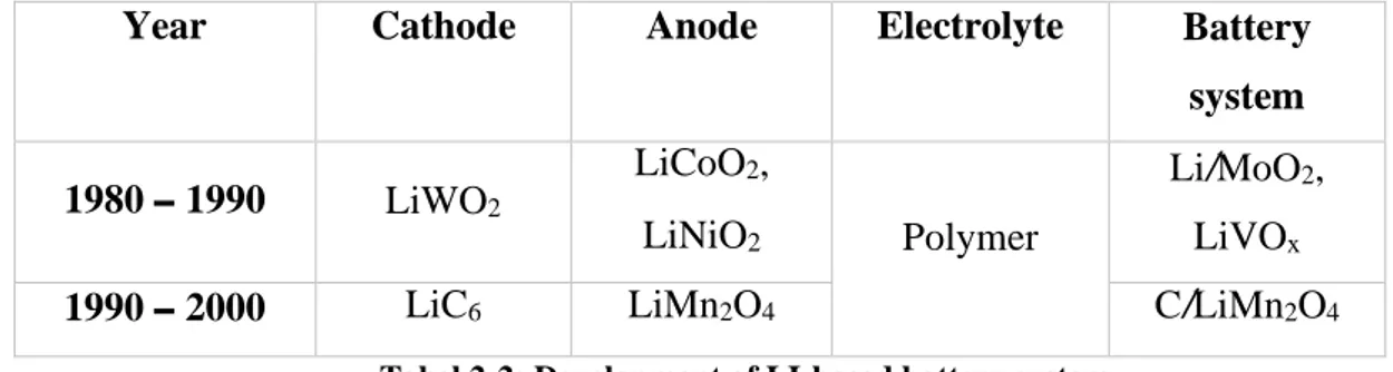
Table 2
Year Cathode Anode Electrolyte Battery
system 1980 – 1990 LiWO2 LiCoO2, LiNiO2 Polymer Li/MoO2, LiVOx
1990 – 2000 LiC6 LiMn2O4 C/LiMn2O4
Tabel 2-2: Development of LI-based battery system
Li-ion cells should be operated with in a safe operating voltage range and if the limitations are exceeded the battery can be damaged, also fire will generate. So, to avoid damage and fire Li-ion cells should not charge exceeding the save voltage limit or discharge beneath the limited voltage. Also, the cells should be operated between the given temperature range to increase the lifetime.
21
Figure 18
Figure 19
Fig 2-10: Safe operating area charging and discharging
Normally Li-ion cells are discharged in constant current. Without damaging the cell, Li-ion can discharge to 20% of SOC (state of charge) by a constant current rate but after that, the discharging should do by using constant voltage. Charging voltage is large than the discharging voltage generally and because of that all charging energy does not involve when discharging.
Fig 2-11: Charging and Discharging of Li-ion batteries
The electrochemistry of the Li-ion battery on charging shown below: • At the negative electrode
𝐿𝑖𝑥𝐶6+ 𝑥𝐿𝑖+ + 𝑥𝑒− → 𝐿𝑖𝐶6
• At the positive electrode
𝐿𝑖𝐶𝑜𝑂2 → 𝑥𝐿𝑖 + 𝑥𝑒−+ 𝐿𝑖(1 − 𝑥)𝐶𝑜𝑂 2
22 The electrochemistry of discharge as follows:
• At the negative electrode
𝐿𝑖𝐶6 → 𝐿𝑖𝑥𝐶6 + 𝑥𝐿𝑖+ + 𝑥𝑒− • At the positive electrode
𝑥𝐿𝑖 + 𝑥𝑒−+ 𝐿𝑖(1 − 𝑥)𝐶𝑜𝑂
2 → 𝐿𝑖𝐶𝑜𝑂2
Modern Li-ion storage batteries are powerful and light, even though relatively expansive. They do not contain metallic lithium, but ions only. They hold their charge. A lithium-ion battery pack loses only about 5 percent of its charge per month, compared to a 20 percent loss per month for NiMH batteries. They have no memory effect, which means that you do not have to completely discharge them before recharging, as with some other battery chemistries. Lithium-ion batteries can handle hundreds of charge/discharge cycles.
Pros: Lithium has the lowest standard reduction potential, which makes it a very good anode. E.m.f. = 3 V, lightness and no memory effect; no decrease of potential of discharge since during process of both discharge and recharge (intercalation and de-intercalation of lithium ions) modification neither of grains dimensions nor crystalline structure of electrodic materials occurs.
Cons: Rather expensive; solvent can be flammable. Reliability and durability needs to be improved. They start degrading as soon as they leave the factory. They will only last two or three years from the date of manufacture whether you use them or not. They are extremely sensitive to high temperatures. There is a small chance that, if a lithium-ion battery pack fails, it will burst into flame.
2.2.4 Lithium Polymer Battery
Li-Polymer batteries placed in fourth as electric vehicle batteries. Nevertheless, because of safety purposes Li-polymer batteries are not use for commercial purpose. Anodes of the Li-Po battery made of using Lithium or Carbon intercalated with Lithium. The battery chemistry of Li-Po has increased the specific energy and power of the Lipolymer battery than other available batteries. Because of the battery electrode’s kinetics, the ability to absorb and release ions have limited the specific power and the life cycle.
Electrochemistry of the Li-Polymer battery displayed as follows: • Cathodic reaction when charging and discharging 𝐿𝑖𝑥𝑀𝑋 ↔ ∆𝑥𝐿𝑖++ ∆𝑥𝑒− + 𝐿𝑖
𝑥−∆𝑥𝑀𝑋
• Anodic reaction When charging and discharging 𝐶6 + ∆𝑥𝐿𝑖+ + ∆𝑥𝑒− ↔ 𝐿𝑖∆𝑥𝐶6
23
Table 3
3 Future Developments
Battery technologies are central to delivering significant advances in a wide range of industries, from electric vehicles to renewable power. This has catapulted battery technology to the top of the priority list for many players, leading to a huge boom in investment, as companies try to build key positions in the market. However, this investment frenzy threatens to lead companies to rush forward without asking themselves key questions. What will the landscape look like when the dust settles? Which technology will dominate the battery space in the future, and what are the potential scenarios for future growth? How do I (as a chemical company, utility, investor, battery manufacturer, automotive manufacturer, mobility provider or government / regulator) prepare for the future and position myself to benefit? There is no simple answer to these questions, as they depend on a range of factors, from the speed of innovation to the ability to reduce costs of existing technologies.
Battery technologies are an essential catalyst to unlock growth and new advances in sectors such as electric vehicles (EVs), electronic devices and battery energy storage (BES) for renewable energy. The increasing reliance on battery storage is driving enormous demand – overall, battery applications are expected to become a $90 billion-plus market by 2025, up from $60 billion in 2015.
Lithium-ion (Li-ion) batteries, have seen rapid improvements in performance and cost due to a combination of greater economies of scale and research and development. However, there are still burning unmet needs to be solved. Next-generation technologies are required to deliver a step-change in performance of key battery characteristics. Much of the development in this area is being led by ambitious start-ups, working in both the Li-ion market (such as on silica anodes, solid-state electrolytes and advanced cathodes) and in alternative technologies, such as flow and zinc-air batteries.
We can identify multiple types of operating models for batteries in energy-storage applications, including at grid scale and for residential storage, in which it can be linked to wind turbines and rooftop solar panels. Based on their needs from batteries, these operating models can be divided across two axes: 1) frequency of discharge and 2) length of discharge. The applications and key needs of each quadrant are shown in Table 3-1.
Table 3-1: Summary of key needs per application in battery energy storage
24
Table 4
From the previous table we can see:
1) Frequency of discharge high and length of discharge high, the battery should have high energy and have low cost per cycle.
2) Frequency of discharge high and length of discharge low, it has low cost per cycle, fast charging and high power.
3) Frequency of discharge low and length of discharge high, it has low capital cost and high energy. 4) Frequency of discharge low and length of discharge low, it has low capital cost and high power. Li-ion batteries have improved dramatically over the past 25 years, enabling improved performance in consumer electronics and the introduction of new applications such as drones and EVs. However, to accelerate these and other applications, new innovation is vital – a step-change in performance is required. As table 3 below demonstrates, there are still major unmet needs in each application – such as:
• Cost, reliability and charging time for EVs
• Cycle lifetime and cost for high-frequency stationary battery energy storage
• Safety across multiple applications
25
Figure 20
From the table we can see the unmet requirements for the batteries, like for EVs are the capital cost, charging time and reliability.
A lot is happening in next-generation technologies. A host of battery technologies using alternative materials are being developed by ambitious start-ups, while there is increasing innovation within the Li-ion space primarily focusing on three areas: silica anodes, advanced cathodes and solid-state electrolytes.
we will focus our attention on the future of Li-ion batteries applying the three above innovations and obviously the batteries must fulfill the unmet requirements like the capital cost, charging time and reliability in terms of security “less fire more power”.
3.1 Challenges is Lithium-ion battery
Despite of the development over two decades of LIB industry, the relatively low specific capacity of current commercial cathode (lithium cobalt oxide, 140-170mAh/g) and anode (graphite, 370mAh/g) materials limits the specific energy of LIB. Usually from the point of4 view of LIB market, 5-8% capacity increase each year for both LIB manufacturers and customer applications. However, it is difficult to achieve desired capacity due to the limitation of electrode materials availability in the last few years. Some companies are looking for other options to reduce the cost of LIBs, such as longer cycle life and higher cutoff voltage. But LIB researchers and scientists are still facing the problem of improving energy density for next generation LIBs. Changing the active materials for both cathode and anode electrodes is the key to improve the battery performance. Great effort had been made for synthesis new materials with higher specific capacities, such as Lix Niy Co1-y O2 for cathode and Silicon for anode.
Figure 1.3 shows potential electrode materials for LIBs and many works are going on these projects which could lead us to next generation advanced LIBs.
Fig 3-1: Potential materials for cathode and anode
Furthermore, safety of LIB is also a critical issue for large scale applications, especially in EVs and grid energy system, which demand higher capacities by using battery packs. The Battery Management System (BMS) has been invented to reduce the potential of any accident and minimize the damage before it happens. Several accidents involving LIBs have been reported in elsewhere. The last challenge for LIBs industry is the manufacturing cost due to its complicated production processes. Basically,
26 current LIBs have three types of format, cylindrical cell, prismatic cell and pouch cell. All of them have mature manufacturing processes, and cylindrical cells (18650 format) have highest production efficiency and lowest cost since fully automatic production line is available. Moreover, cylindrical cells provide consistent performance and no swelling which make them more reliable for battery packs. This is part of the reason for Tesla to choose cylindrical battery types for their EV application. Prismatic cells were the main power source for cell phones, but pouch cells have been rapidly seizing market share in the last few years, especially smart phone, tablet and other small portable devices. One of the main advantages is the diversity of cell shape which can provide more freedom for those who design new devices. Furthermore, pouch cell has excellent safety since the battery will not explode in extreme situations. However, compared with cylindrical and prismatic cell, the cost is much expensive due to more processes and production efficiency. It is also difficult to have a full automatic production line as the cell shapes will be changed regularly.
3.2 Silica anodes
Silicon, graphene, and sometimes the two of them combined together have all been suggested as potential replacements for graphite (negative electrode anode) in the electrodes of lithium-ion batteries. Silica has higher energy capacity than graphite, the normal material for anodes. This is leading to it being blended through graphite anodes, with the aim of eventually moving towards full silica anodes. These can offer theoretical increases in energy density of up to 40 percent. However, for this to happen, issues in cycle lifetime have to be overcome, in which the anode pulverizes itself upon its 300 percent volume expansion while charging. Ongoing innovations use only minor silica concentrations, limiting potential density increases to 10–20 percent. While all three of these options bring attractive properties to the table—most importantly, a very high theoretical capacity—those properties are lost in the real world. Silicon electrodes crack and break after just a short number of charge/discharge cycles. Meanwhile, the use of graphene on electrodes is limited because graphene’s attractive surface area is only possible in single stand-alone sheets, which don’t provide enough volumetric capacitance. Layer the graphene sheets on top of each other to gain that volumetric capacity, and you begin to lose that attractive surface area.
Now researchers at Kansas State University (KSU) claim to have developed a technique that uses silicon oxycarbide that makes the combination of silicon and graphene achieve its expected greatness as an electrode material. It is better to use silicon combined with graphene than a bulk silicon electrode, but nano-silicon/graphene electrodes fail to satisfy key requirements for any practical applications and they have poor volumetric capacity, high cost, and low cycling efficiency—too much lithium is lost irreversibly with each charge-discharge cycle. What’s more, their mechanical and chemical instability that can lead to rapid capacity decay. To overcome this, the KSU researchers turned to the high temperature glass ceramic, silicon oxycarbide. the KSU team created a self-standing anode material consisting of silicon oxycarbide glass particles embedded into a chemically modified graphene oxide matrix. A heated silicon resin decomposes so that “the constituent silicon, carbon, and oxygen atoms are arranged in a random 3-D structure, and any excess carbon precipitates out into string-like or cellular regions. Such an open 3-D structure renders large sites for reversible lithium storage and smooth channels for solvated lithium-ion transportation from the electrolyte.” This stands in stark contrast to crystalline silicon, which undergoes an alloying reaction with lithium that results in enormous volume changes and also an irreversible reaction with the electrolyte that leads to chemical instability and fading capacity as the charge-discharge cycles add up. The KSU researchers claim that the electrode has a capacity of approximately 600 mA/g or 400 mA/h per cubic centimeter of the electrode after 1020 cycles. The researchers expect that the power density (the maximum amount of power that can be supplied per unit mass) will be more than three times that of today’s Li-ion batteries.
27
Figure 21
Figure 22
Fig 3-2: Glass nanoparticles embedded in graphene (3-D structure)
3.2.1 The solutions for Si anode practical application
Based on the requirement of current LIB market, it is quite clear that finding new active materials for next generation LIB is the priority. The development of cathode is mainly focusing on “Li-rich NMC” which combine the beneficial effects of Ni, Co and Mn with6 some Li in the transition metal layers and demonstrate a higher capacity exceeding 280 mAh/g. For anode part, according to Table 1.1, Si anode has been considered as one of the most promising anode candidates due to its super high specific capacity (4200mAh/g), which is ten times higher than graphite anode (372mAh/g). Nevertheless, the key problem for Silicon based anode is its huge volume change (420%) during lithiation/delithiation process, which leads to rapid pulverization and mechanical integrity damage of Si electrode, resulting loss of electrical contact and rapid capacity fading (Figure 3-3). In addition, binders and electrolyte are also crucial to address the key problem of Si-based electrode during cycling based on mechanical and electrochemical properties.
28
Table 5
Si anode materials:
Table 3-3 Comparison of various anode materials (all the capacity numbers are based
on materials in the delithiated state except lithium metal)
Generally, there are two solutions to overcome huge volume change of silicon anode: preparation of nanoscale materials and make porous Si anode. Nano-structured Silicon anode can dramatically reduce the volume effect during charging/discharging, which minimizes the electrode swelling thereby improves the cycle stability. Many efforts have been devoted to design various Si nano structures during last 10 years, such as Si nanoparticles (SiNPs), Si nanowires (SiNWs), Si hollow nanotubes (SiHNTs), Si core-shell, Si/C composite and SiOx.
3.2.2 Silicon-carbon anode
The Si–C anode materials are usually prepared by methods such as vapor deposition, high temperature solid phase synthesis, mechanical alloying, electrostatic electrospinning; the latter three methods require high temperature treatment. The methods mentioned above are the most widely used and easiest to implement.
3.2.3 Vapor deposition
Vapor deposition includes chemical vapor deposition (CVD) and physical vapor deposition (PVD). CVD is a chemical process used to produce high quality, high performance solid materials. The process is often used in the semiconductor industry to produce thin films. CVD is widely used in microfabrication processes to deposit materials in various forms, including monocrystalline, polycrystalline, amorphous and epitaxial. These materials include: silicon (SiO2, germanium, carbide,
nitride and oxynitride), carbon (fiber, nanofibers, nanotubes, diamond and graphene), fluorocarbons, filaments, tungsten, titanium nitride and various high-k dielectrics. Chemical vapor deposition (CVD) in which hydrocarbons are decomposed over a substrate is perhaps the most popular route since it is a technique commonly adopted by the semiconductor industry and it is also relatively facile to set up in research laboratories. PVD describes a variety of vacuum deposition methods, which can be used to produce thin films and coatings. PVD is characterized by a process in which the material goes from a condensed phase to a vapor phase and then back to a thin film condensed phase. The most common PVD processes are sputtering and evaporation. PVD is applied in the manufacture of items that require thin films for mechanical, optical, chemical or electronic functions. Common industrial coatings applied by PVD are titanium nitride, zirconium nitride, chromium nitride and titanium aluminum nitride. Of the two vapor depositions, CVD is often used to prepare silicon–carbon composite materials.
3.2.4 High temperature solid phase synthesis
High temperature solid phase synthesis refers to a method that under high temperature (1000–1500°C) and through contact with a solid interface, reaction, nucleation and crystal growth response generates a large number of compound oxides. High temperature solid phase synthesis could be a common method to prepare Si/C composite materials, and in order to prevent the inert phase of Si/C the reaction temperature is often controlled under 1200°C.
29
3.2.5 Mechanical alloying
In contrast to high temperature solid phase synthesis, the materials prepared by mechanical alloying often have smaller particles, larger specific surface area and more uniform structures. Mechanical alloying (MA) is a solid-state powder processing technique involving repeated cold welding, fracturing and re-welding of blended powder particles in a high-energy ball mill to produce a homogeneous material. MA is now shown to be capable of synthesizing a variety of equilibrium and non-equilibrium alloy phases starting from blended elemental or pre-alloyed powders.
3.2.6 Electrostatic electrospinning
Electrospinning is a fiber production method, which uses electric force to draw charged threads of polymer solutions or polymer melts up to fiber diameters in the order of some hundred nanometers. Electrospinning shares characteristics of both electros spraying and conventional solution dry spinning of fibers. The process does not require the use of coagulation chemistry or high temperatures to produce solid threads from solution. This makes the process particularly suited to the production of fibers using large and complex molecules. Electrospinning from molten precursors is also practiced and this method ensures that no solvent can be carried into the final products. Electrospinning is a particularly low cost, simple and versatile method to produce nanofibers from various kinds of materials, and the improved coaxial electrospinning can fabricate nanotubes and core–shell structural nanofibers.
3.2.7 Modification of silicon–carbon anode materials
The main problems of silicon–carbon anode materials, such as low first discharge efficiency, poor conductivity and poor cycling performance need to be improved. When studying the modification of silicon–carbon anode materials, we usually take the following three aspects into consideration:
1) Use different nanostructures to buffer the volume change of silicon, avoid the damage of generated SEI film on the electrode surface and avert the explosion of new surface during the process of circulation, in order to reduce the irreversible capacity loss and improve the cycling stability;
2) We can significantly change the carbon material elements and the surface activity and improve the electrochemical properties through heteroatom doping, including non-metallic elements (boron, nitrogen, sulfur, phosphorus) and metal elements (K, Al, Ga, V, Ni, Co, Cu, Fe)
3) Apply compound modification treatment by combining different forms of carbon with silicon to form uniform conductive network structures and to prepare silicon–carbon composite materials with good electrical conductivity, good adhesion and high chemical stability.
3.2.8 Structural modification of silicon–carbon anode materials
Carbon-based nanomaterials have unique properties that make them useful for many technical applications, including lightweight construction, electronics, energy generation, environmental technology and medicine. Nanomaterials exhibit physical and chemical properties that are different from, and normally much better than, those of the bulk forms. These outstanding properties are often determined by the microstructure. Carbon materials with excellent mechanical flexibility, high electronic conductivity and chemical stability in electrolytes have drawn much attention for the development of binder-free and lightweight electrodes. The most recent advance in the applications of nanowires (NWs), nanofibers (NFs), nanotubes (NTs) and nanospheres (NSs) in the structure of silicon– carbon nanomaterials in LIBs are often mentioned. Table 3-4 lists some studies using combinations of Si–C anode materials (NWs, NFs, NSs), in the form of material structures and electrochemical properties. From these studies it can be seen clearly that anode materials with nanostructures can
30 significantly improve the electrochemical cycling performance of lithium ion batteries.
Table 6
Tabel 3-4: Electrical properties of silicon–carbon anodes with different structures. Qr1,the first reversible capacity;
CE,coulombicefficiency; QdN(N), discharge capacity in Nth cycle; C.R.N., capacity retention in Nth cycle. NWs, nanowires; NFs, nanofibres; NTs, nanotubes; NSs, nanospheres.
3.2.9 Silicon–carbon nanowires
Nanowires are needed in many nanoscale applications. Various types of nanowires have been produced, including some with diameters ranging from about 50 to 100 nm. The process of a novel design of carbon–silicon core–shell nanowires for high power and long-life lithium-ion battery electrodes is schematically illustrated in figure 3-4. Amorphous silicon was coated onto carbon nanofibers to form a core–shell structure and the resulting core–shell nanowires showed great performance as anode material. They show a high charge storage capacity of about 2000 mAh/g and good cycling life. They also have a high coulombic efficiency of 90% for the first cycle and 98–99.6% for the following cycles. Bogart’s group reported a solution-based synthesis of Si nanowires with a conductive carbon skin. Electrodes made with Si nanowires coated by pyrolyzed carbon shells exhibited high capacities of over 2000 mAh/g