University of Pisa and Scuola Superiore Sant’Anna
Master Degree in Computer Science and Networking
Laurea Magistrale in Informatica e Networking
Master Thesis
On Cloud-based multisource Reliable Multicast
Transport in Broadband Multimedia Satellite Networks
Candidate:
Emnet Tsadiku Abdo
Supervisors:
Dr.-Ing. NICOLA TONELLOTTO (ISTI- CNR)
Dott. ALBERTO GOTTA (ISTI- CNR)
2
Table of Contents
Chapter I: Introduction ... 3
1.1 Cloud computing and Grid computing ... 3
1.2 Cloud computing background ... 4
1.3 Cloud computing definition ... 4
1.4 Cloud computing adoption and usage ... 5
1.5 Commercial Cloud computing platforms ... 6
1.6 Summary ... 8
Chapter II: Current Cloud Architecture Technologies ... 9
2.1 IP Network Architecture ... 9
2.1.1 An Access Network ... 9
2.1.2 A Core/Backbone Network ... 10
2.1.3 An Edge Network ... 10
2.2 Cloud computing Architecture ... 11
Chapter III: Wireless technologies ... 16
3.1 Advantages of wireless technology ... 16
3.2 Drawback of wireless technologies ... 16
3.3 Different type of wireless technologies ... 17
3.3.1 Wi-‐Fi ... 17
3.3.2 WiMAX ... 18
3.3.3 Universal Mobile Telecommunications System (UMTS) ... 19
3.3.4 High Speed Packet Access (HSPA) ... 20
3.3.5 HSPA+ ... 21
3.3.6 Long Term Evolution (LTE) ... 22
3.4 Satellite Communication ... 23
3.4.1 Geostationary satellite-‐based ... 23
3.4.2 Medium earth orbit satellite-‐based ... 24
3.4.3 Low earth orbit satellite-‐based ... 25
3.5 Summary ... 25
Chapter IV: Reliable Multicast Transport in Satellite Networks ... 27
4.1 Multicast Transport Protocols ... 27
4.2 NORM protocol Messages ... 28
4.2.1 Sender Messages ... 30
4.2.2 Receiver Messages ... 31
4.3 NORM Scalability ... 33
4.4 State of the Art on File Delivery in Cloud Networks ... 34
4.5 The case study: Reliable Multicast in a satellite network ... 37
Chapter V: Conclusions and Future Works ... 51
References ... 52
3
Chapter I: Introduction
Cloud computing is rapidly emerging as a new information technology platform. This promising set of computing technologies changes our perspective of the way we realize computation by enabling the use of storage, processing and higher level elements such as operating systems or software applications. This distributed computing paradigm treats system and data as a service and it does not need such resources to be physically stored on a specific set of machines. Cloud Computing has become one of the most publicized technology in recent times and has got lots of attention from media as well as from web space hosting providers, data centers and virtualization software providers. The term Cloud computing is broad and includes several aspects of the concept of “service”, thus sometimes results are unclear. Most talk about this topic is still vague and everyone in the Cloud computing field, from experts to Cloud providers, has his own definition of Cloud computing. The following subsections explain in more detail the existing definitions of Cloud computing describe different classes of Cloud services and provide examples about the concrete application of Cloud paradigm.
1.1 Cloud computing and Grid computing
The term Cloud computing and Grid computing both refer to data centers and computing as a common suggestion. This leads many to actually believe that this two computing paradigms can be used interchangeable. In one of their earlier white papers on the topic IBM specifically highlights the differences and the evolution of Cloud computing over Grid computing. Grid computing is mainly concerned with coordination of resource sharing and problem solving in dynamic way. Hence, it denotes dividing a large task into many smaller ones that run on parallel servers. In fact, the objective of Grid computing is to give users access to IT resources whenever they need them. According to IBM, the key advantage is that Cloud computing not only is able to divide a large computational task into many smaller tasks to run on parallel servers, but Could also support non Grid environments, with requirements far from the large computational task model. In doing that, Cloud computing has the potential to bring out the advantages of Grid computing, such as the single point of access for all the computing needs of the customers while reducing the technology issues and entry barriers, such as the seamless integration of dynamic virtual organizations.
4
1.2 Cloud computing background
To the present date, there are many ways in which computational power and data storage facilities are provided to users; for instance, access to a single laptop or to the location of thousand of compute nodes distributed around the world [8].
In addition, user requirements vary with the hardware resources, memory and storage capabilities, network connectivity and software installations. Thus, the outsourcing computing platforms has emerged as a solution for users to handle the problem of building complex IT infrastructures.
Cloud computing is generally identified with large pool of easily usable and accessible virtualized resources, which can be dynamically reconfigured to adjust to a variable load scale. In other words, the Cloud appears to be a single point of access for all the computing needs of consumers. This paradigm is strongly promoted in recent days, because of some of its main features, such as virtualization, resource sharing, scalability and self- management, usability, pay-per-use model.
1.3 Cloud computing definition
The first and most difficult issue when first facing Cloud computing concerns figuring out a common definition which everyone can agree on. This section reports several Cloud computing definitions so far provided by different researchers.
"A Cloud is a type of parallel and distributed system consisting of a collection of interconnected and virtualized computers that are dynamically provisioned and presented as one or more unified computing resources based on service-level agreements established through negotiation between the service provider and consumers.” [1]
According to this first definition, the “Cloud” is not only a bunch of clusters and Grids. It is extended by the usage of virtualization technologies for maximizing physical resources to respect the negotiated service quality.
“Cloud Computing refers to both the applications delivered as services over the Internet
and the hardware and systems software in the data centers that provide those services. The services themselves have long been referred to as Software as a Service (SaaS). The data center hardware and software is what we will call a Cloud. When a Cloud is made available in a pay-as-you-go manner to the general public, we call it a Public Cloud; the service being sold is Utility Computing. Thus, cloud computing is the sum of SaaS and utility computing, but does not include small or medium-sized data centers, even if these
5
rely on virtualization for management. People can be users or providers of SaaS, or users or providers of utility computing.” [2]
This definition emphasizes that Cloud computing offers a wide set of IT resources: from computing power to computing infrastructure, applications, business processes, to personal collaboration. Indeed, Cloud computing eliminates the upfront commitment from users side. Computing resources are available on demand, delivered to users as a service. Users are charged per usage for the use of these computing resources.
1.4 Cloud computing adoption and usage
Over the past few years, Cloud computing service has generated a lot of interest and become one of the many buzzwords in technology.
Cloud computing services are enabling customers to access the IT services they need to run their businesses from the Cloud without any infrastructure investment or any services deployed in-house. However it should be highlighted that Cloud computing is not only about technological improvements of data centers [4].
Enterprises must consider the benefits, drawbacks and other effects of Cloud computing on their enterprises and usage practices before adopting and using Cloud computing [5]. The adoption of Cloud Computing is highly dependent on the maturity of organizational and the technology itself. The adoption of Cloud computing will not expose enterprises back end computing requirements to Cloud providers rather; a heterogeneous computing e n v i r o n m e n t has t o b e established which is composed of dedicated servers, Clouds and public Cloud providers.
Services can be scalable by load balancing and other solutions that can be easily turned behind the scenes, without any application awareness or involvement. Cloud is there to keep clients media and applications on the Internet so that they can access them from any device anywhere whenever they want it, as contend to leaving it on an hard drive.
As an example, Cloud storage providers allow you to access files from different computers. In theory, with Cloud services, customers can access diverse types of media, such as photos, e-books and videos across multiple devices. Good Cloud services should be able to integrate with multiple devices and provide not only display photos and videos, but has also more than this, like share files and allow blogging or website creation. For instance, Cloud music providers should be able to provide all songs on both computers and mobile devices.
6
Current state-of-the-art Cloud services are a best way to access and manage digital life on the Web in a nice way. The benefit of storing data in the Cloud is that clients can access their documents anywhere using an Internet connection.
1.5 Commercial Cloud computing platforms
This section highlights the different kind of commercial Cloud services and features currently available to customers, including their history as well as what they offer.
Apple iCloud is the latest brand of Apple's Cloud computing services. It has previously been branded as iTools in 2000 and MobileMe in 2008. It is a typical Cloud storage solutions, and a good example of an application that almost exemplifies what Cloud computing is all about. In the context of Cloud computing, Apple employs a Cloud architecture for storing user synchronization data like email, calendar and so on, and personal multimedia, in such a way that, for example, a music file can be kept on a remote server and it can be downloaded to many Apple devices like iPods, iPhones, iPads, while helping to manage the content easily. In its simplicity, iCloud "simply manages links to uploaded content" hosted in turn by Microsoft's Windows Azure (which is an application platform offered by Microsoft) and Amazon Web Services.
Microsoft Windows Azure is a platform supporting a distributed generic programming environment by enabling applications written in a .NET language to run in the Cloud environment managed by the underlying Azure operating system. The user has access to certain functions that are integrated in his application code to take advantage of the automatic scalability properties of the distributed Cloud environment. However, the user has no control whatsoever on the underlying. It is fundamental for companies that would adopt Azure-based SaaS to understand that Windows Azure OS will run only at Microsoft data centers, as Microsoft does “not envision selling Widows Azure for on-premises deployment”, due to the alleged complex structure and features of their multi-tenant global datacenter. The intention is for Microsoft to provide “on-demand” vs. an “on premises” platform that will allow for scale out SaaS applications.
Amazon Web Services (AWSes) are a set of remote Web services offered by Amazon providing a Cloud computing platform so that the services can be delivered over Internet. The most well known services offered by this vendor are Amazon EC2 (Elastic Cloud Computing) and Amazon S3 (Simple Storage Service). EC2 is a central part of Amazon
7
Cloud computing platform, providing an elastic virtual computing environment that meets specific customer needs. It enables customers to launch and manage service instances in Amazon’s data centers using APIs or available tools and utilities. EC2 services are priced by hourly usage of instance units as well as by data transfer sizes. Moreover, the Amazon EC2 works in conjunction with other Amazon Web Services such as Amazon Simple Storage Service (Amazon S3), Amazon Simple DB and Amazon Simple Queue service (Amazon SQS) to provide a complete solution for computing, query processing and storage across a wide range of applications. Amazon S3 is a storage service for the Internet, which is designed to make Web-scale computing easier for developers. Amazon S3 has a simple Web interface that can be used to store and retrieve any amount of data, at any time, from anywhere on the Web. Data can be downloaded or used with other AWSes, such as EC2. It gives to any developer access to the same highly scalable, reliable, fast, inexpensive data storage infrastructure that Amazon uses to run its own global network of Web sites. The best way to think about Amazon S3 is a globally available distributed hash table (DHT) with a high- level access control [7].
Google App Engine is an application-developing platform provided as a service that can be potentially exploited to enable user-made applications to run on Google's own infrastructure. This allows developers to easily write scalable applications, but they can only run a limited range of applications designed for that particular infrastructure via a large set of proprietary APIs. Google’s “Cloud suite” can be confusing: there’s no one-stop destination that hosts all your media. You have to use Picasa to deal with your photos, Gmail for your e-mail, Music Beta for online music storage and Google Docs for your documents.
Dropbox is basically a Web-based file hosting service that allows file- sharing acting as a virtual folder that lives on your computer or mobile device. It assists customers to "drop" files in an online storage locker and to access them later on from anywhere. Since Dropbox client works the same on every major platform and you can also access your files through the Drop box Web interface on any device with a Web browser. It allows making an edit to a file, and the changes synchronize across all customers devices connected to Dropbox. This service is the most widely used now. Customers can connect all their devices with this Cloud service. Once the file is placed on a shared folder, this file will be transferred to other devices connecting to this shared folder.
8
1.6 Summary
Cloud computing is the next big wave in computing. Without any doubt, Cloud computing is truly a revolutionary concept for many business organizations. As seen earlier, Cloud computing provides for better and easier management of data. Cloud Computing holds a lot of promise and it is likely to be a major influence on hosting and application development. However, this promise cannot be achieved without giving special attention to the underlying Cloud computing architecture.
The next chapter elaborates that the success of Cloud computing is largely based on the effective implementation of this architecture. Indeed, Cloud computing architecture is not just based on how the application works with the intended users. The hardware and application components have to work together seamlessly, otherwise Cloud computing will not be possible.
9
Chapter II: Current Cloud Architecture Technologies
This chapter presents an overview of the IP network architecture before explaining the current Cloud computing architecture (Cloud architecture for short). Cloud architecture is the conceptual model that defines the structure and behavior of software systems involved in the delivery of Cloud computing. This process typically involves multiple Cloud components (Cloud resources, services, middleware, software components), communicating with each other over application programming interfaces, usually web services. Cloud architecture extends to clients, where web browsers and/or software applications access Cloud applications. The Cloud architecture is classified based on its level of abstraction, whether it is an Infrastructure-as-a-Service Cloud (IaaS), a Platform-as-a-Service Cloud (PaaS) or a Software-as-a-Service Cloud (SaaS). The purpose of this classification is to facilitate communication between different Cloud technologies and services, and to support the design of software systems.
2.1 IP Network Architecture
A network architecture is a modeling of the complete computer communication infrastructure, which provides a framework and a technological foundation for designing, building and managing a communication network. It has a layered structure. Layering is a modern network design principle, which divides the communication tasks into a number of smaller parts, each part accomplishing a particular sub-task, and interacting with the other parts in well-defined ways. Layering allows the parts of a communication network to be designed and tested without a combinatorial explosion of cases (i.e., testing different combinations of possible hardware and software components on a PC), keeping each design relatively simple.
2.1.1 An Access Network
An Access Network is part of a communication network, which connects subscribers to their immediate service provider. For example; the networking switching subsystem (GSM core network) in GSM (Global System for Mobile Communications) which connect local providers to each other is an access network. The increasing growth of broadband connectivity, over both wired and wireless networks, had lead the development of new services, allowing the individual to stay always connected at home, at work or on the move. Thus, an access network is a way for communications providers to deliver their new high
10
bandwidth services to the subscribers. In this way, a service provider can retain and satisfies the needs of its customers.
Access network also refers to the data network that links each user with edge network (i.e., provides information exchange between an access network and core network) of Service Provider. It is a route between the subscriber's and the service provider. An access device is required for the access network, which helps to gain access to network resources from a distant location. Common access devices are routers and modems. An access device can assemble multiple channels of information including voice and data across a single shared access link to a service provider.
2.1.2 A Core/Backbone Network
A Core/Backbone Network is the central part of a communication network (i.e., collection of terminals, links and nodes are connected, to enable communication between users of the terminals.) that provides various services to customers that are connected by an access network. The devices and facilities in the core/backbone networks are switches and routers. In the switching part of the Universal Mobile Telecommunications System (UMTS) network, a core network provides call control and performs mobility and high-level security functions such as location updating and authentication. Generally speaking, the backbone network’s capacity is better in-terms of high-capacity communication facilities than the networks connected to it. Sometimes, decision about security and traffic are not handled at the edge level. This impacts the core network performance and scalability, while at the same time requiring more bandwidth in all parts of the network, thus driving up cost and complexity. To have a more reliable and fault tolerant core network with high level of security, it is a best practice to push the intelligence and decision-making into an access and edge devices, and keep the core devices as simple as possible.
2.1.3 An Edge Network
An Edge Network provides information exchange between an access network and core network. The devices and facilities in the edge networks are switches and routers, which are often called edge devices. There is an ingress (input) and egress (output) edge device for all connections. The edge device aggregates ingress traffic for high speed transmission in the core/backbone network and then distributes egress traffic to end users through access devices. The edge network provides entry points into carrier/service provider core/backbone networks (i.e., the edge network connects users and applications, while network traffic enters and exits from the network).Due to the variety and complexity of customer access technologies and multiple choices of a core network, a switch of the edge network for a wide area network
11
(WAN) can be a multiservice unit, meaning that it supports a wide variety of communication technologies, including voice and IP over dial-up connections. An edge device may provide enhanced services, such as virtual private network (VPN) (i.e., a VPN is a network that uses primarily public telecommunication infrastructure, to emulate a private network linked through Internet. It allows remote computers to act as though they were on the same secure, local network.) support, voice over IP, and QoS services.
Figure 1: Interactions between an access network and core network with services provider.
2.2 Cloud computing Architecture
Cloud architectures address difficulties concerning large-scale data processing. In the past, data processing was quite challenging, it was very difficult to get as many machines as an application needed. In order to distribute them and to make coordination among them, a large-scale job was required on different machines. This made difficult to auto-scale up and down based on dynamic workloads. Cloud architectures overcome all these issues in a decent way. An application that resides on top of Cloud architectures actually runs in a physical location that is autonomously selected by the Cloud provider. This application simply takes advantage of APIs of Internet-accessible services that scale on-demand plus the usage of resources sometimes can be seasonal. The complexity, reliability and scalability logic of the underlying services remains implemented and hidden inside the Cloud.
12
Figure 2: Cloud computing architecture.
Cloud architectures use Internet access and operate on the basis of on-demand services. To fulfill this demand, the underlying computing infrastructure is utilized when necessary. For instances, to process a user request, all the necessary resources on-demand like compute servers will be exploited, do the required task, then release the unneeded resources. During this operation, the application can scale up or down based on resource needs. Cloud Computing infrastructure allows business organizations to achieve more efficient use of their IT hardware and software investments. They do this by automating the management of the group of systems as a single entity.
It is possible to make a physical server into actually multiple servers, each running with independent operating systems. This method is called server virtualization. By maximizing the output of individual servers, server virtualization reduces the need for more physical machines. It provides resources to users by showing an abstract computing platform instead of exposing the physical characteristics of a Cloud computing infrastructure. Thus, Cloud services are deployed and scaled-out quickly through the rapid provisioning of virtual machines. Generally speaking, virtualization implementation consists of two levels, namely hardware layer and software layer. The former mainly includes virtualization of computer cluster system hardware resource, such as memory virtualization, storage virtualization and I/O virtualization. The latter mainly refers to operation system virtualization, which ensures
!"
Page 7 !"#$%&'()*+*,&-.-/0*12*34546*!"%#"%7)-*8-9(/":"'$6*28;*,1<=***
Cloud Computing Architecture
Major building blocks
Reference Architecture
! Basis for documentation, project communication
! Stakeholder and team communication
! Payment, contract, and cost models
Technical Architecture
! Structuring according to XaaS Stack
! Adopting Cloud Platform paradigms
! Structuring cloud services and cloud components
! Showing relationships and external endpoints
! Middleware and communication
! Management and security
Deployment Operation Architecture
! Geo-location check (Legal issues, export control)
! Operation and monitoring
Page 8 !"#$%&'()*+*,&-.-/0*12*34546*!"%#"%7)-*8-9(/":"'$6*28;*,1<=*** #$%&'()*"(+"("#*),-.*" /0(&%$)1"(+"("#*),-.*" 23%)(+&)4.&4)*"(+"("#*),-.*" /((#" #((#" 2((#"
!"#$%&!#'($)*+,&-./0*)1/)$.1&234&5XaaS6
7&allows comparisons, maps to common dictionary
5 (3 (6* 1 * 3 &" 7880-.(&-$3" #*),-.*" #&$)(6*" 90$4:";43&-1*" 23%)(+&)4.&4)*" 90-*3&"" 23%)(+&)4.&4)*" #* .4 )-&< " 90$4:"9$184&-36"7).=-&*.&4)*"" !"#$%&'()*+",-%.*(/"0)*(%/",(/11"23$'/" 4-%()1)5."6*()7/"
13
each guest operating system resides on the same physical hardware without knowledge of the other guest operating systems (A guest OS is an operating system that is installed in a virtual machine or disk partition in addition to main OS).
NIST (National Institute of Standards and Technology) has given a working definition of Cloud Computing architecture by describing five essential characteristics, three Cloud services models and four Cloud deployment models. The essential characteristics of Cloud Computing according to NIST are:
• On-demand-self-service: A consumer can unilaterally provision computing capabilities, such as server time and network storage, as needed, automatically without requiring human interaction with each service’s provider.
• Broad Network Access: Capabilities are available over the network and accessed through standard mechanisms that promote use by heterogeneous client platforms (e.g., mobile phones and laptops).
• Resource Pooling: The provider’s computing resources are pooled to serve multiple consumers using a multi-tenant model (a multi-tenant describe multiple customers using the same public Cloud), with different physical and virtual resources dynamically assigned and reassigned according to consumer demand.
• Rapid Elasticity: Capabilities can be rapidly and elastically (flexible) provisioned, in some cases automatically, to quickly scale out and rapidly released to quickly scale in. To the consumer, the capabilities available for provisioning often appear to be unlimited and can be purchased in any quantity at any time.
• Measured Service: Cloud computing systems automatically control and optimize resource usage by providing a metering capability to the type of services (e.g., storage, processing, bandwidth, or active user accounts).
Moreover, NIST identified three Cloud services models often referred to as “SPI model”, i.e., software, platform and infrastructure models:
• Cloud Software as a Service (SaaS): this is a capability in which the consumer uses the provider’s applications running on the Cloud.
• Cloud Platform as a Service (PaaS): the capability provided to the consumer is to deploy onto the Cloud infrastructure consumer-created applications using
14
programming languages and tools supported by the provider. The consumer does not manage or control the underlying Cloud infrastructure, network, servers, operating systems, or storage, but the consumer has control over the deployed applications and possibly application hosting environment configurations.
• Cloud Infrastructure as Service (IaaS): Cloud enables on-demand provision of computational resources, in the form of virtualized resources in a Cloud provider’s data center. The Service Providers manage a large set of resources including processing, storage, network capacity and other fundamental computing resources. Eventually, a Cloud can be deployed according to four standard models.
• A Public Cloud is the standard Cloud deployment model, in which a service provider makes resources available (such as applications and storage), which will be exposed to public Cloud services via Internet. Public Cloud services do not necessarily means they are free, they can also be subjected to payment based on usage model.
• Private Cloud: these days, there exists tons of information on Internet regarding Private Cloud: What it is about and how you can benefit from it. All those description concluded as, private Cloud is a type of the cloud architecture that is available only for a single organization.
• Community Cloud: as it was clearly mentioned in the NIST definition, in this kind of Cloud deployment model, the infrastructure of the Cloud is exploited by several organizations but it will support a specific community with shared concerns for-example, healthcare.
• Hybrid Cloud: is a Cloud infrastructure composed of two or more Clouds i.e. Private, community or public [3].
15
16
Chapter III: Wireless technologies
In today's fast moving world ongoing technology, the evolution of wireless technology offers a significant potential for the creation and transformation of markets for communications services and products. The concept of a wireless communication system is almost deceptively easy to understand. The main reason that drives the evolution of wireless technology is the need for higher speed, bandwidth, and global access. Clients are in need of information related to business, entertainment, etc., with higher quality and speed. This line of thinking represents a fundamental shift to wireless technology. The goal of this section is to focus on the most common wireless technologies in use today. A comparison between these different technologies will be also giving in the following sub-chapters.
3.1 Advantages of wireless technology
The widespread reliance on networking as well as the increasing demand on Internet and online services are strong testimonies to the benefits of shared data and resources. Wireless solutions advance these benefits by reaching out, where cable and fiber cannot reach, since the inherent nature of wireless is that, it doesn't require wires or lines to accommodate users to access shared information, e-mail, and applications without the constraints of physical connection. As such, the system will carry information across different geographical areas that are prohibitive in terms of distance, cost, access, or time. Wireless has got a fully comprehensive access technology portfolio to work with existing broadband access technologies so quickly and reliably. It also commonly provides a competitive alternative to broadband wired line or provides access in geographies that don't qualify for loop access. One of the main advantages is the ability to provide anytime and anywhere connectivity. The widespread implementation of wireless allows people to easily connect to the Internet to download information and to exchange files. Yet, despite the decrease in cost, the data rate and capabilities of these devices have increased, allowing faster, more reliable wireless connections.
3.2 Drawback of wireless technologies
Security is one of the main concerns when it comes to wireless network, as wireless is a public frequently used network for transferring any data type. Hence, its interface is highly risky to be used for private information exchange due to security issues. In fact, transferring
17
confidential data over a wireless network is a serious risk. Such kind of information must use the wired technologies because they are more safe and sound. In somehow, the security issue can be better exploited by using a robust security protocol like WPA [Wi-Fi Protected Access] or WPA2 [the most current security protocol which replaced WPA]. Another common problem associated with a wireless network, is when more and more users use the same frequency. It results that the throughput will be lower than the link rate. In addition to the multiple access issue, the intrinsic nature of wireless communications is relies on error prone channels that significantly affect the reliability of a wireless link in terms of throughput, as well. Wireless technologies are, in practice, impaired by a number of obstacles like walls, large distance, doors and the device itself. For such reasons, the wireless signal is not stable and this makes difficult the maintenance of QoS(Quality of Service). Even if wireless is a very promising technology, wired technologies (e.g. Fiber) still outperform all the types of wireless network.
3.3 Different type of wireless technologies
In this section, I will outline the most common wireless technologies with a short preview of the incoming 4G of mobile cellular network.
3.3.1 Wi-‐Fi
Wi-Fi "Wireless Fidelity" follows a standard set of rules to achieve their communication; the standard is known as IEEE802.11 (Institute of Electrical and Electronic Engineers for local area networks and metropolitan area networks (LAN/MAN) or just 802.11). Wi-Fi operates in the 2.4 GHz range with up to 11 Mbps data rates and is backward compatible with the 802.11 standard. 802.11b uses a technology known as complementary code keying (CCK) modulation, which allows for higher data rates with less chance of multi-path propagation interference (duplicate signals bouncing off walls).Devices that follow 802.11a standard are considered “Wi-Fi Certified”. Wi-Fi certified equipment, tested and approved by the Wi-Fi Alliance, bears the Wi-Fi logo. Only Wi-Fi certified equipment is guaranteed to be interoperable, even though non-certified equipment also follows the standard laid out by IEEE. Wi-Fi is access or edge-network technologies. This means it offer alternatives to the last-mile wireline network. Beyond the last-mile, Wi-Fi relies on similar network connections and transmission support infrastructure.
A new variant of Wi-Fi technology, known as 802.11g (a third modulation standard of 802.11 standard) has been introduced in 2003 in order to optimize the bandwidth. It uses 2.4GHz
18
frequency rangewith a new, more advanced form of spread-spectrum technology known as orthogonal frequency-division multiplexing (OFDM) and it can achieve speeds of up to54 megabits per second in the 2.4GHz band. The 802.11g standard is backwards-compatible with the 802.11b standard, meaning that devices that support the802.11g standard can also work with 802.11b.However, 802.11g cannot reliably support more than one stream of video. A further new amendment is represented by 802.11n standard: the connection speeds up to 300Mbps (802.11g reaches only 54Mbps) can compete in performance with Ethernet wired networks. The previous version 802.11g uses channels at 20MHz while the '802.11n can use 40MHz channels, theoretically doubling the speed of a connection. Another positive aspect of 4 GHz-dual-band models is that they are able to work in mixed mode at 2.4 GHz for older machines and for 5GHz models new generation.
The transfer speed increases of four times with 802.11n compared to the previous 802.11g version thanks to MIMO (multiple-input multiple-output) able to transmit more data at a time. The principle behind MIMO technology is an enabled device can utilize multiple wireless signals and antennas (called MIMO technology) instead of one only. 802.11n MIMO does not necessarily mean: it is a protocol, while the first is more of technology option. Since MIMO is covered in 802.11n, it is likely to confuse the two. In addition, MIMO is NOT and will not be compatible with 802.11n. It is therefore fundamentally wrong to compare (if not in terms of actual performance and features of the software) systems, to the rest of the devices compatible with 802.11n.This standard 802.11n connections should support data rates of over 100 Mbps. 802.11n also offers somewhat better range over earlier Wi-Fi standards due to its increased signal intensity. 802.11n equipment will be backward compatible with 802.11g gear.
3.3.2 WiMAX
WiMAX (Worldwide Interoperability for Microwave Access) has a network architecture similar to Wi-Fi; both create hot spots but, from a technological point of view, they differ significantly; Wi-Fi can cover only few hundred meters, while WiMAX has, in theory, a maximum range of 50 km. WiMAX stands for "Worldwide Interoperability for Microwave Access and is an inter operability specification based on IEEE 802.16. WiMAX is a broadband telecommunication technology for fixed users (in the range of 10-66GHz), Non-LOS (Line of sight) communications (in the range of 2-11GHz), and mobile deployments (in the range of 2-6 GHz). Indeed, WIMAX is the first major mobile standard to offer an IP based broadband wireless communication, similar to that of 802.11/Wi-Fi networks. At its
19
heart, its purpose is to ensure that the broadband wireless radios manufactured for customer use interoperate from vendor to vendor.
The 802.16a standard was developed for wireless MANs operating on licensed and unlicensed radio-frequency (RF) bands between 2 GHz and 11 GHz, at data speeds of up to 75 megabits per second (Mbps), with low latency and efficient use of spectrum space. Security is enhanced by encryption features. Forward error correction (FEC) and space/time coding optimize accuracy under marginal signal conditions. The maximum range can be extended to approximately 30 miles (48 kilometers) with some sacrifice in throughput. The 802.16a specification is ideally suited for advanced communications methods such as voice over IP (VoIP) and prioritized data traffic.
The early iterations of IEEE 802.16 focused on line-of-sight (LOS) applications using high-frequency bands between 10 to 66 GHz. More recently, efforts have been focused on specifying amendments to the early standards to support non-line-of-sight (NLOS) applications between 2 to 11 GHz. The 802.16-2004 standards, more commonly known as 802.16d, were published in 2004. 802.16d is essentially the fixed version of WiMax. This standard is meant to serve as a wireless replacement for DSL for areas where running copper wire does not make economic sense. It is also a viable solution for wireless backhaul of WiFi access points and potentially for the backhaul of Cellular Voice networks.
WIMAX supports both time division duplex and frequency division duplex, both using a burst transmission format, whose framing mechanism supports adaptive burst profiling, in which transmission parameters, including the modulation and coding schemes, can be adjusted individually on a frame-by-frame basis. Thus, WiMAX operates at higher speeds, over greater distances, and for a greater number of customers compared to the services of Wi-Fi. Thus, WiMAX provides a wireless alternative to cable, Digital Subscriber Line (DSL), and copper wire for last-mile broadband access. The main goal of WiMAX standard is to enable the adoption of advanced radio features in a uniform fashion. The advantage of WiMAX is that a single station can serve a number of users in a range of several Kilometers and its deployment in much faster and cheaper.
3.3.3 Universal Mobile Telecommunications System (UMTS)
UMTS is a third-generation (3G), meaning it is characterized by a single global frequency and the voice quality is comparable to the public switched telephone network. Indeed, this generation provides a high-quality video and audio with symmetrical or asymmetrical data transmission rates.
20
Today's cellular telephone systems are mainly circuit-switched, with connections always dependent on circuit availability. In a packet -switched connection, a virtual connection is always available to any other end point in the network. Users will have access through a combination of terrestrial wireless and satellite transmissions.
UMTS support for both packet-switched and circuit switched based transmission of text, digitized voice, video, and multimedia at data rates up to 2Mbps data rate, 384 kb/s in urban environment with speed up to 60 km/h and 144 kbps in rural areas for speed up to 150 km/h. This offers a consistent set of services to mobile computer and phone users no matter where they are located in the world.
In general, UMTS are more efficient in use of the available spectrum with flexibility to allow the introduction of new services and technologies. However, UMTS requires a new Radio Access network not superimposed to GSM in 1800 or 1900 MHz. The terrestrial radio interface of UMTS is based on two duplexing modes that are Frequency Division Duplex (FDD) for macro-and micro-cell (bit rate < 384 Kb/s) and Time Division Duplex (TDD) for Pico cell (bit rate < 2Mb/s) with low mobility. The higher bandwidth of UMTS also offers new services, such as video conferencing. UMTS promises to realize the Virtual Home Environment in which a roaming user can have the same services to which the user is accustomed when at home or in the office, through a combination of transparent terrestrial and satellite connections.
3.3.4 High Speed Packet Access (HSPA)
High Speed Packet Access (HSPA) is a combination of two Mobile Communications protocols, High Speed Downlink Packet Access (HSDPA) and High Speed Uplink Packet Access (HSUPA). HSPA allows for very high data speed for Internet connectivity. More in details, HSDPA belongs with the family of solutions that use packet data transmissions, which include also GPRS and EDGE. Current HSDPA deployments support down-link speeds of 1.8, 3.6, 7.2 and 14.0 Mbps. However, 14Mbps is the peak theoretical throughput. In fact, it's far from its theoretical maximum due to the existence of interference limitations. So far, this technology has just exceeded 3.6 Mbps for two years since HSDPA can achieve good throughput in areas of low interference.
Watching online videos and downloading files are subjected to the performance of HSDPA. This is a testimony for clarifying the fact that Internet bandwidth usage is asymmetrical, majority of the population downloads more compared to uploading. Due to this usage pattern HSDPA first deploy before doing HSUPA. This technology improves the downlink side as much as possible. Allocating equal bandwidth to uplink and downlink result in a huge waste
21
of bandwidth. Since the bandwidth allocation must take in to account the network traffic of the users. There is some scenario in which only HSDPA is deployed while HSUPA is pretty much absent.
The main advantage of HSDPA technology is that communication range practically equals distance range of a base station with fast link adaptation. The drawback here is that high speed is available only for downlink; uplink will be at the baseline WCDMA speed 384Kbit/s. We can expect this drawback to be overcome with the appearance of HSUPA. The main aim of HSUPA is to increase the uplink data transfer speed in the UMTS environment and it offers data speeds of up to 5.8 Mbps in the uplink. The Enhanced Uplink feature shall aim at providing significant enhancements in terms of user experience (throughput and delay) and/or capacity. The coverage is an important aspect of the user experience and that it is desirable to allow an operator to provide for consistency of performance across the whole cell area. So the goal should be to increase in overall cell throughput on the uplink. Thus, a gain in user throughput can be achieved which reduces packet delays. For instances, sending email with very large attachments or upload file in a file sharing network is a good example that exemplifies how the uplink speed can be improved by using HSUPA techniques.
HSUPA achieves its high performance through more efficient uplink scheduling in the base station and faster retransmission control. HSUPA has dedicated channel that is shared in time among different users with short transmission interval, as low as 2ms. Fast Hybrid Automatic Repeat Request technique is used to improve the efficiency of error processing.
3.3.5 HSPA+
HSPA+ (High Speed Packet Access Plus) is also known as HSPA Evolution and Evolved HSPA. HSPA+ was first standardized in 3GPP Release 7 and standardization has continued through to Release 10. HSPA+ is an enhanced version of high-speed 3G wireless networks. Because it is so closely related to 3G and is not a new, built-from-the ground-up technology, HSPA+ has been called a 3.5G network instead of a true 4G network. But HSPA+ networks are capable of delivering 4G speeds, with download speeds between 5 megabits per second and 8 mbps. HSPA+ will apply some of the techniques developed for Long Term Evolution (LTE) and allow operators to extend the life of their HSPA networks. HSPA+ brings improved support and performance for real-time conversational and interactive services such as picture and video sharing, and Video and Voice over Internet Protocol (VoIP) through the introduction of features like Multiple-Input Multiple-Output (MIMO) antennas, Continuous Packet Connectivity (CPC) and Higher Order Modulations.
22 3.3.6 Long Term Evolution (LTE)
This section provides an overview of long term evolution, which is the leading technology for next-generation mobile broadband. Wireless customers want to be truly engaged with advanced communication devices that provide a similar immersive experience as found in today’s wired networks. Whether, it’s downloading or uploading large files, video or social networking. Wireless customers want to be able to communicate whenever and wherever they choose around the globe with a good service quality. Therefore, Wireless believes LTE is the best technology ever that can meets a customer need with the global scale as needed. 3GPP LTE is a 4th generation wireless network, which is typically a radio platform technology that will let to achieve a higher peak throughput at higher spectrum bandwidth. Unlike the previous wireless technologies standard: UMTS and HSPA Evolution and WIMAX, LTE dramatically achieve greater speeds and pervasive connectedness. Even if, HSPA and its evolutions are the dominant mobile data technology for the next decade, this family of standards must evolve toward the future long term technology. The following table describes the evolution of HSPA technologies towards LTE technology.
HSPA HSPA+ LTE
Peak speeds 1.8 Mbps–14.4 Mbps (Downlink) 384 Kbps–2 Mbps (Uplink) 42Mbps downlink 22Mbps uplink 100Mbps 50Mbps Average user throughput Up to 2Mbps
downlink but uplink can vary depending on the devices 5Mbps downlink 3Mbps uplink 5-12Mbps downlink 2-5Mbps uplink Table 1: Evolution of HSPA towards LTE.
Table 1 is a verification for the higher user throughput achieved in both downlink and uplink transmission. In the same way that 3G coexists with second generation (2G) systems in integrated networks, LTE systems will coexist with 3G and 2G systems. These technologies make a shift from mobile service to broadband connections by using TCP/IP (the core protocol of the Internet). This protocol makes it easy for the delivery of higher-level services. LTE is designed to support voice, Video and multimedia in a packet domain.LTE operate in both TDD and FDD operation modes at downlink peak data rates up to 100Mbps with 20MHz bandwidth and Uplink peak data rates up to 50Mbps with 20MHz bandwidth. Since
23
LTE has a Scalable bandwidth up to 20MHz, this helps operators to migrate easily their networks and users from HSPA to LTE over time.
The overall objective for LTE is to provide an extremely high performance radio-access technology that offers full vehicular speed mobility and that can readily coexist with HSPA and earlier networks. LTE reduce latency to 10ms round-trip time between user equipment and the base station and to less than 100ms transition time. It incorporates top of-the-line radio techniques to achieve performance levels beyond what will be practicable with CDMA approaches, in particular in larger channel bandwidths.
3.4 Satellite Communication
Satellite communication has been introduced in the mid 1990s; satellite became the first mainstream consumer wireless Internet service. The heart of a satellite communications system is a satellite-based antenna in a stable orbit above the earth. In a satellite communication system, two or more stations on or near the earth communicate via one o r more satellites that serve as relay stations in the space. Satellite access initially worked only in one direction, for downloading information. Subscribers needed to install a standard dial-up modem and to use a telephone line with the satellite to make a functional system. Newer forms of satellite service remove this limitation and support full two-way connectivity. Satellite communications is comparable to optical fiber in terms of importance, during the evolution of telecommunications and data communications. Compared to other forms of wireless Internet service, satellite exploits the advantage of availability. Requiring only a small dish antenna, satellite modem and subscription plan, satellite works in almost all rural areas not serviced by other technologies. However, satellite also offers relatively low performing wireless Internet. Satellite suffers from high latency (delay) connections due to the long distance signals must travel between Earth and the orbiting stations. Satellite also supports relatively modest amounts of network bandwidth. There are a number of ways categorizing communications satellites depending on coverage area, service type whether it is fixed, broadcast and mobile service satellite and also they can be also categorized depending on their usage for instance, if it is commercial, military and experimental.
3.4.1 Geostationary satellite-‐based
This type of satellite communications is very common nowadays. The term geostationary comes from the fact that the satellite appears to be stationary in the sky as seen by ground-based observer. The satellite is located at an altitude of 35,863 km. Satellites in a
24
geostationary orbit can “see” nearly half the Earth, which makes this orbit especially useful for broadcasting, weather, and telecommunications satellites. These kinds of communication are mainly used in TV and radio broadcast mainly due to their coverage area.
Geo satellite has an advantage of minimizing interference from surface based source and from other satellite due to the fact that, in this kind of satellites one can use a highly directional antenna and can be left in position without further adjustments. Unlike LEO, objects in GEO are not naturally removed from orbit by atmospheric drag. Instead, the debris moves in an enormous doughnut shaped ring around the equator as the gravitational forces of the Sun, Moon, and Earth pull on the objects.
The known limitation of Geo satellite is the latency (250ms) due to their altitude range, this introduce unacceptable latency into two-way data networks communication especially significant in voice application. Another disadvantage of geostationary satellites is that, since ground stations at higher than roughly 60 degrees latitude has difficulty reliably receiving signals at low elevations. Satellite dishes at such high latitudes level would need to be pointed almost directly towards the horizon. The signals suffer from the largest amount of atmosphere and it can be blocked also by buildings and land topography.
3.4.2 Medium earth orbit satellite-‐based
A medium earth orbit (MEO) is located between geostationary and LEO stationary satellites. The most common usage of this satellite is for navigation purpose, such as GPRS. Because, MEO satellites are closer to the earth than geostationary satellites, earth-based transmitters with low power and modest-sized antennas can access the system. MEO satellites orbit are located at higher altitudes than LEO satellites, this is useful for footprint (coverage area on the earth's surface), which is greater for each satellite.
In addition, the cost of launching a MEO satellite is very less than that of GEO satellite. MEO are able to overcome the TCP performance limitation by reducing the latency from 250ms (GEO latency) to tenth of millisecond, which is comparable to a terrestrial network performance. The more the satellite is closer to the ground, the more satellites are needed to cover the earth. For such reason, a continuous coverage is achieved by providing a more satellites for MEO.
The major types of satellites that use this orbit are those that provide services for navigation systems, such as the United States (US) Navstar Global Positioning System (GPS) and the Russian Glonass satellites.
25 3.4.3 Low earth orbit satellite-‐based
Lastly, LEO satellites do reduce the round-trip time from tenth of millisecond to just a few tens of millisecond. The transmission power is not powerful as that of GEO and MEO satellites due to their low orbit nature. The round trip time is highly variable depending on, if the satellite is directly or on the horizon. Due to this, the TCP performance can varies since the TCP retransmissions are highly tied to the round-trip time.
LEO has certain advantages such as: it is much cheaper and convenient for placing a satellite, to perform experiments, fix and install new equipment. LEO can be easily affected by bad weather, this result in low quality on satellite-based communications. A more frequent handed off is needed during data transmission via LEO as the satellite moves out of range, because LEO is not fixed in space respect to the rotation of the earth. LEO based telecommunication systems are useful for underdeveloped territories to get a satellite telephone service in areas where it is either too expensive or not geographically possible to deploy land lines.
Table 2: The different type of orbital for satellite communication application.
3.5 Summary
Throughout this chapter the overview of wireless network, different technologies and pros and cons along with these technologies were discussed. Wireless technology is becoming an ever-growing part of human life providing each time new different services, which makes it preferable. Wireless communications brings huge benefits to the clients and therefore becoming a must for industry. Wireless is convenient and often less expensive to deploy than fixed services, but wireless is not perfect. There are device limitations, incompatible standards and technical difficulties that may ultimately prevent wireless technologies from reaching out their full potential. Wireless technologies often tend to increase convenience and decrease safety. Long Term Evolution technology remains in a research and development
Orbits GEO MEO LEO
Orbital period 24 hr 5 to 10 hr 1.5 to 2 hr
Altitude range 35,863
Km 8000 to 18000 Km 500 to1500 Km
Round-trip
propagation 250ms Tens of ms Several ms
Visibility
26
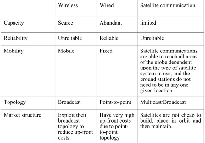
mode, and industry specifications are not fully ratified. Table 3 summarizes the comparison among the overviewed wireless technologies.
This thesis is only concerned with Geo satellite communication due to several advantages that come along with this technology. One of the most known advantages, for quite long time,
is the coverage area. It covers most of the inhabited portions of the entire earth excluding only the areas near the north and south poles (as it was described in geostationary satellite section).
Wireless Wired Satellite communication
Capacity Scarce Abundant limited
Reliability Unreliable Reliable Unreliable
Mobility Mobile Fixed Satellite communications
are able to reach all areas of the globe dependent upon the type of satellite system in use, and the ground stations do not need to be in any one given location.
Topology Broadcast Point-to-point Multicast/Broadcast
Market structure Exploit their broadcast topology to reduce up-front costs
Have very high up-front costs due to point-to-point topology
Satellites are not cheap to build, place in orbit and then maintain.
27
Chapter IV: Reliable Multicast Transport in Satellite Networks
We have discussed at the beginning of the Chapter 1how Cloud computing is rapidly emerging as a new information technology platform. That description was followed by Cloud computing architecture (in Chapter 2). Chapter 3 was an introduction and a description on wireless technologies, which helped us to understand the different technologies and advantages of having a wireless network, in particular the satellite network. Satellites have a role in providing the multicast service for providing uniform accessibility. The multicast communication is easy via satellite, because the signal sent via the satellite can be received by any receiver within the coverage area of the satellite.
This chapter will introduce the overview of a NORM protocol message and the multicast protocol specification. The remaining section of this thesis will present a methodology for overcoming the delay on each packet, for example, for file transfer application in NACK-oriented reliable multicast (NORM) protocol scenario.
4.1 Multicast Transport Protocols
At present, there is no standardized, Internet-based multicast transport protocol that provide effective, dynamic congestion control methods for safe, wide scale deployment of end-to-end rate adaptive applications (for example, file transfer application). Recent research and standardization efforts are beginning to address these issues.
In computer networks, we distinguish between three main forms of communication: • unicast, where a sender wants to transmit messages to one receiver,
• broadcast, where a sender wants to transmit to all the other nodes, and
• multicast, where a sender wants to transmit to a subgroup of the receivers connected to the network.
In multicast communication, a sender send its messages to a specific multicast address, and it is up to the network to make sure that every member of the group defined by the address gets a copy of the messages.
The Internet does not yet provide multicast communication to all its users. However, a growing number of networks connected to the Internet offer multicast. This opens the way for developing more applications that presuppose Internet multicast communication. Multicast based applications cover a wide range of categories, from chat groups and multi-player games, to multimedia conferencing tools and stock price subscriber services [20].
28
Different types of multicast applications have different kind of requirements to the communication services provided by the network. For example, a multimedia conferencing application that makes it possible for users to see and talk to each other in real time is sensitive to delay, i.e., the time it takes to send data packets to the receivers. The application can tolerate some delay of video data, but the voices of the participants become unintelligible if the audio data suffers large variances in delay. If a data packet gets lost once in a while, the tool still functions quite well. However, the data that does arrive must arrive on time. On the other hand, an application that allows several users to edit shared documents requires reliable data delivery, i.e., that every data packet arrives, that they arrive in the same order they were sent, and that only one copy of each packet is delivered.
The problem is that the Internet cannot provide neither timely nor reliable delivery of data between applications. The Internet Protocol (IP), which ties together networks with different technologies, provides a best effort service: It will do its best to deliver data packets to the recipients, but it makes no guarantees about the delivery. Data packets may be reordered or duplicated, and they may arrive late, or not arrive at all.
The multicast protocol that this chapter describes NORM is an example of how this problem is handled, both in the Internet and in networks in general: a set of services that are useful to a group of applications are identified and implemented in a transport protocol, a protocol which uses the underlying network’s packet delivery services to provide communication between application programs on computers attached to the network. The protocol then tries to provide the services despite the limitations of the network, by using various techniques for preventing, detecting, and correcting errors.
4.2 NORM protocol Messages
The Negative-acknowledgment (NACK) Oriented Reliable Multicast (NORM) protocol [10] provides reliable transport of data from one or more sender(s) to a group of receivers over an IP multicast network. The primary design goals of NORM are to provide efficient, scalable, and robust bulk data (e.g., computer files, transmission of persistent data) transfer across possibly heterogeneous IP networks and topologies. NORM protocol supports the reliable participation to multicast session with a minimal coordination among senders and receivers. NORM allows senders and receivers to dynamically join and leave multicast sessions at will, with a marginal overhead for control information and timing synchronization among
29
participants. To accommodate this capability, NORM message headers contain some common information allowing receivers to easily synchronize to senders throughout the lifetime of a reliable multicast session. NORM can self-adapt to a wide range of dynamic network conditions with little or no pre-configuration, e.g., in case of congestion situations on network bottlenecks due to traffic overload. The protocol is tolerant to inaccurate round-trip time estimations or loss conditions that can occur in mobile and wireless networks; it can correctly and efficiently operate even in situations of heavy packet loss and large queuing or transmission delays.
Table 4 lists the five principal NORM protocol message types. The first three listed are considered “sender” messages and the remaining two are “receiver” messages.
Message Type Purpose File
values
NORM_DATA Application data and FEC content 2
NORM_INFO Application transport object
meta-data
1
NORM_CMD Sender protocol control and
signaling
3
NORM_NACK Receiver requests for repair content 4
NORM_ACK Receiver acknowledgement 5
Table 4: Principal NORM message types.
Unlike some other transport protocols, the NORM design separates the functions of reliability, congestion control, and flow control into distinct mechanisms. The bulk of the NORM Protocol Specification addresses reliability mechanisms based upon packet-level FEC concepts and specifies congestion control operation that is compatible with the ubiquitous Transmission Control Protocol (TCP). However, the congestion control mechanism is supported using header extensions (figure 5) to the NORM protocol messages and alternative schemes to meet different application or network environment.
There are some common message fields contained in all NORM message types. All NORM protocol messages begin with a common header with information fields as follows:
30
0 1 2 3 0 1 2 3 4 5 6 7 8 9 0 1 2 3 4 5 6 7 8 9 0 1 2 3 4 5 6 7 8 9 0 1 +-+-+-+-+-+-+-+-+-+-+-+-+-+-+-+-+-+-+-+-+-+-+-+-+-+-+-+-+-+-+-+-+
|version| type | hdr_len | sequence | +-+-+-+-+-+-+-+-+-+-+-+-+-+-+-+-+-+-+-+-+-+-+-+-+-+-+-+-+-+-+-+-+ | source_id | +-+-+-+-+-+-+-+-+-+-+-+-+-+-+-+-+-+-+-+-+-+-+-+-+-+-+-+-+-+-+-+-+
Figure 4: NORM common message header format.
Additionally, a header extension mechanism is defined to expand the functionality of the NORM protocol. When header extensions are applied, they follow the message type's base header and precede any payload portion. There are two formats for header extensions, both of which begin with an 8-bit header extension type ("hel") field. One format is provided for variable- length extensions with "het" values in the range from 0 through 127. The other format is for fixed length (one 32-bit word) extensions with "het" values in the range from 128 through 255.
The formats of the variable-length and fixed-length header extensions are given in Figure 5.
0 1 2 3 0 1 2 3 4 5 6 7 8 9 0 1 2 3 4 5 6 7 8 9 0 1 2 3 4 5 6 7 8 9 0 1 +-+-+-+-+-+-+-+-+-+-+-+-+-+-+-+-+-+-+-+-+-+-+-+-+-+-+-+-+-+-+-+-+ | het <=127 | hel | | +-+-+-+-+-+-+-+-+-+-+-+-+-+-+-+-+ | | Header Extension Content | | ... | +-+-+-+-+-+-+-+-+-+-+-+-+-+-+-+-+-+-+-+-+-+-+-+-+-+-+-+-+-+-+-+-+
0 1 2 3 0 1 2 3 4 5 6 7 8 9 0 1 2 3 4 5 6 7 8 9 0 1 2 3 4 5 6 7 8 9 0 1 +-+-+-+-+-+-+-+-+-+-+-+-+-+-+-+-+-+-+-+-+-+-+-+-+-+-+-+-+-+-+-+-+ | het >=128 | reserved | Header Extension Content | +-+-+-+-+-+-+-+-+-+-+-+-+-+-+-+-+-+-+-+-+-+-+-+-+-+-+-+-+-+-+-+-+
Figure 5: NORM Variable-Length Header Extension Format. 4.2.1 Sender Messages
NORM_DATA: The NORM_DATA messages are supposed to be used by senders in order to convey application content and FEC encoded repair packets for that content reactively as needed (and/or proactively).This message type is used both for sending new data segments,