2016
Publication Year
2020-05-04T09:21:43Z
Acceptance in OA@INAF
The ATHENA optics development
Title
Bavdaz, Marcos; Wille, Eric; Shortt, Brian; Fransen, Sebastiaan; Collon,
Maximilien; et al.
Authors
10.1117/12.2233037
DOI
http://hdl.handle.net/20.500.12386/24412
Handle
PROCEEDINGS OF SPIE
Series
9905
Number
The ATHENA Optics Development
Marcos Bavdaz
1, Eric Wille
1, Brian Shortt
1, Sebastiaan Fransen
1, Maximilien Collon
2, Nicolas
Barriere
3, Alexei Yanson
3, Giuseppe Vacanti
3, Jeroen Haneveld
4, Coen van Baren
5, Karl-Heinz
Zuknik
6, Finn Christensen
7, Desiree Della Monica Ferreira
7, Michael Krumrey
8, Vadim Burwitz
9,
Giovanni Pareschi
10, Daniele Spiga
10, Giuseppe Valsecchi
11, Dervis Vernani
121 European Space Agency, ESTEC, Keplerlaan 1, PO Box 299, NL-2200 AG Noordwijk, The Netherlands 2 cosine Research B.V, Oosteinde 36, NL-2361 HE Warmond, The Netherlands
3 cosine Science&Computing B.V, Oosteinde 36, NL-2361 HE Warmond, The Netherlands 4 Micronit Microfluidics B.V., Colosseum 15, NL-7521 PV Enschede, The Netherlands
5
SRON, Sorbonnelaan 2, NL-3584 CA Utrecht, The Netherlands 6 OHB System AG, Perchtinger Str. 5, 81379 München, Germany
7 DTU Space, Elektrovej 328, 2800 Kgs Lyngby, Denmark
8 Physikalisch-Technische Bundesanstalt (PTB), Abbestr. 2-12, D-10587 Berlin, Germany 9 MPI f. extraterrestrische Physik, Giessenbachstrasse 1, D-85748 Garching, Germany 10 INAF Osservatorio Astronomico di Brera, Via E. Bianchi 46 I- 23807, Merate (LC), Italy
11 Media Lario S.r.l., Località Pascolo, I-23842 Bosisio Parini (LC), Italy 12 RUAG Schaffhauserstrasse 580, 8052 Zürich, Switzerland
ABSTRACT
ATHENA (Advanced Telescope for High ENergy Astrophysics) is being studied by the European Space Agency (ESA) as the second large science mission, with a launch slot in 2028. System studies and technology preparation activities are on-going.
The optics of the telescope is based on the modular Silicon Pore Optics (SPO), a novel X-ray optics technology significantly benefiting from spin-in from the semiconductor industry. Several technology development activities are being implemented by ESA in collaboration with European industry and institutions. The related programmatic background, technology development approach and the associated implementation planning are presented.
Keywords: X-ray optics, X-ray astronomy, ATHENA, Silicon Pore Optics, X-ray telescopes, X-ray testing, Technology
preparation
1. HOLISTIC TECHNOLOGY DEVELOPMENT AND TECHNOLOGY SPIN-IN
ATHENA is a technologically very innovative mission, relying on advanced cryogenic and semiconductor detector instruments and a high performance novel telescope optics technology [1-3]. The required large effective area, several times larger than that of its predecessor XMM-Newton, combined with an improved angular resolution, less than half that of XMM-Newton, while effectively maintaining the mass, would not be achievable with the established X-ray optics technologies. A new optics technology, the Silicon Pore Optics (SPO) is being developed to cover the needs of ATHENA [4-36].
The conflicting requirements of improved figure and lower mass demands the use of an advanced material, which can be super-polished cost effectively, and has superb mechanical and thermo-elastic properties. Mono-crystalline Silicon is such a material, and it is produced on large scale and with excellent surface finish, both in terms of figure and surface roughness, for the semiconductor industry. The material is strong and light, and has a very good thermal conductivity.
Huge investments have been made by the electronics industry to evolve the equipment and mature the production process to produce 300 mm diameter Silicon wafers with both surfaces polished and accurately parallel.
The spin-in of semiconductor technologies, equipment and processes allowed the cost-effective development of the SPO. Not only is the starting material with super-polished surface finish available off-the-shelf, but also the specialised machinery to process these wafers into the required precision X-ray mirror plates can be purchased on the market. In the later production of the flight mirror the super-polishing of hundreds of square meters of mirror area, as needed for ATHENA, is replaced with the purchase of mass produced industrial wafers.
From the onset of the SPO development, the performance, functional and programmatic requirements of the optics for Europe’s flagship X-ray observatory mission, finally selected as the ATHENA mission concept, were taken into consideration:
• A large area mirror, of diameter up to 3 m, is required. To limit the size of the equipment necessary to produce the optics, and to provide the advantages of serial production, the optics has to be modular, composed of small mirror modules, which can be produced and handled efficiently.
• The optics has to achieve good angular resolution (5” HEW on observatory level) despite the low mass budget allocated to it. This implies the use of very thin mirrors (about 150 µm only) and a base material of excellent uniformity. Such thin mirrors can only bridge small distances un-supported, and requires many mounting points. The invention of the SPO technology, supporting the thin mirrors on longitudinal ribs, has provided the solution. The thin mirrors have to span only small distances, of the order of a millimeter of two.
• The mirror modules are required to have very good thermal stability, in order to simplify the thermal control of the ATHENA optics during launch and operation in space. This implies a very good matching of the Coefficient of Thermal Expansion (CTE) of the materials used to produce the mirror modules. In the SPO the X-ray mirror plates are attached to each other employing ribs machined into the back side of the mirror plates to provide the separation, and without necessitating any glue or other intermediate layer. The surface finish of the X-ray mirror plates is of sufficient quality that the mirror plates bond to each other via hydrophilic bonding, without the need for additional adhesive. The mirror modules are composed of the stacks of mirror plates and the supporting brackets, which are carefully designed to firmly combine the mirror stacks to form the mirror modules, without causing deformations.
• To sustain the launch loads, both vibration and shock, the mirror modules must be rugged by design. The mirror plate stacks have a low mass density and are intrinsically stiff structures with large damage tolerance. The bonding between the mirror plates has to be strong and uniform to provide a predictable performance of the mirror modules under the launch environment. The mirror modules are mounted onto the optical bench (the telescope mirror structure) employing isostatic mounts, largely decoupling the mirror modules from any (transient) deformations of the support structure.
• The very large number of mirror modules demands a high level of process automation and serialisation whilst at the same time ensuring that the requirements on mirror performance, production rate and yield, and cost are met. The mirror plates are produced by slightly modified commercial dicing machines and semiconductor processes, the brackets holding the mirror plate stacks together are CNC machined, as are the isostatic mounting elements.
• The mirror plates are stacked by dedicated robotic equipment, with extensive use of on-line metrology and carefully designed handling tools, operating in clean-rooms without human presence, operated remotely from a separate control room.
• Only one mandrel is required for each mirror plate stack (consisting of 35 mirror plates), i.e. 35 mirror radii are handled with the same tools, significantly reducing the associated costs compared to the electro-forming technology used for XMM-Newton.
• The mirror plate reflective surfaces are fully accessible for the application of reflective coatings and cleaning operations, prior to the stacking. Industrial coating equipment can be used for coating, benefiting from the solar panel and display industry technology and equipment, ensuring the cost-effective processing of large mirror areas as required for ATHENA.
• Specialised companies are used to manufacture the components and tools required, each providing their existing expertise and heritage, minimising the additional R&D work required. This minimises the development risk and ensures sustainability and long term availability of the suppliers throughout the mission development phases.
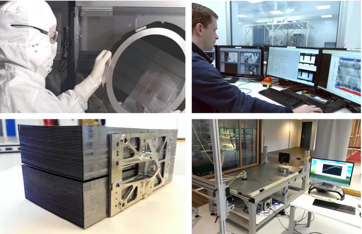
With this approach, the large area, high angular resolution and low mass ATHENA optics technology was developed and is being matured time effectively and cost efficiently. By the early consideration of the later flight model production and qualification the associated performance, cost and schedule risks are minimised. The use of technology spin-in, modularity of the optics and the extensive use of automation are critical to ensuring that the development and later implementation costs are in the line with the programmatic requirements of budget and schedule. Figure 1 shows several aspects of the production of SPO mirror modules and related testing.
Figure 1. The production and testing of Silicon Pore Optics (SPO) mirror modules and their testing. A key constituent of the SPO technology is the spin-in of processes, components and equipment from the semiconductor industry. The X-ray mirror plates are manufactured cost effectively from high-quality Silicon wafers, which are oxidised, ribbed, diced, wedged and coated largely using standard or slightly modified equipment and processes (top left). The mirror plates are then mounted to stacks, using robotic equipment, remotely controlled and assisted by extensive use of precision metrology (top right). Four mirror stacks are then accurately aligned and assembled to a mirror module, employing synchrotron radiation at PTB’s X-ray Pencil Beam Facility [37] (lower left). The mirror modules and its components are environmentally tested (the lower right shows a dedicated shock table) and the X-ray imaging performance is measured in X-ray test facilities.
An early demonstration, in 2007, of the entire production chain, including the production of mirror plates, mandrels, X-ray mirror stacks, complete mirror modules, and their integration into a petal structure provided the basis for the confidence in this enabling technology for the next generation high energy astrophysics observatory, ATHENA. Early extensive synchrotron radiation metrology and evaluation in the established full area illumination long beam PANTER X-ray facility demonstrated the performance and further potential of the SPO technology [37-40].
The SPO technology is continuously evolving, and is steadily approaching the objectives set for the ambitious ATHENA mission. The further improvements of the SPO technology address all steps of the production chain, increasing robustness and improving the performance, employing an iterative development cycle.
2. DEVELOPMENT CYCLE: ITERATIVE IMPROVEMENT
The development and steady improvement of a complex technology like the SPO requires an iterative approach, providing progress in several areas in a stepwise and interlinked methodical way. As illustrated in figure 2, four elements of this development cycle can be identified:
1. The mandrel: in the SPO technology, the geometric figure of the mirror surfaces is defined by a tool, the mandrel, which is re-used for the production of as many mirror stacks as required. The mandrel actually defines the geometric figure of many mirror radii, namely all the 35 mirror plates belonging to a mirror stack. This tool therefore has to be manufactured to high precision, with the required surface geometry for the desired optics. It does also carry any necessary secondary curvatures to ensure the proper performance of the final optics produced with it, i.e. in general the mandrel is not a simple cone, but a rotational paraboloid or hyperboloid, or a more complex figure. The mandrel must be very stiff, with sufficient thickness to maintain its shape also under mechanical loads. What is not required is a super-polished finish of its surface, which substantially reduces the cost of the mandrels. Areas of improvement include: steady decrease of number of trapped particles under the first plate deposited on the mandrel, baseplate attachment and release, reduction of print through, precision positioning references.
2. The mirror plates: the super-polished finish is required on the actual mirror plates. A very large number of mirror plates is required for ATHENA, around 150,000 for the goal configuration, and therefore a cost effective and reliable production is needed. With the technology spin-in from the semiconductor industry, the polishing of 800 m² of mirror surface, as required for ATHENA (two sides of 400 m2 of mirror plate area), is performed by large polishing machines producing high quality wafers at low cost. The structuring of the mirror plates, including the cutting of the grooves which later form the pores, the wedging which makes the mounted mirrors con-focal, the coating and dicing to size is performed by automated processes. In each iteration the level of automation is increased, and the quality of each operation is improved. The individual mirror plates are thus readily available, and a quick response time is ensured for the implementation of improvements. Plate production improvements include the reduction of edge effects and wedging artefacts, optimisation of anticlastic curvature versus rib spacing and membrane (the mirror plate parts bridging the ribs) thickness, and the development of optimised coatings and related equipment.
3. The stacking: the ribbed mirror plates are stacked upon each other to form mirror stacks using a dedicated machine, referred to as the stacking robot. This stacking robot effectively mounts each mirror plate, in a process which copies the accurate figure of the mandrel onto the mirror plates, and which then locks each mirror plate into a multitude of mirror plates, forming a mirror plate stack. The final mirror stack, consisting of 35 mirror plates, is released from the mandrel after its production, and the robot is ready to produce the following stack. The mirror stack does not noticeably deform after the separation from the mandrel, since the many mirror plates are solidly attached to each other after the stacking operation. In the stacking operation the qualities of the mandrel, providing an accurate geometric figure, and of the plates, providing the required super-polished surface, are combined. Stacking developments include: improved cleaning recipes and particle detection to further reduce stack up errors, refinement of the stacking recipe, cone-cone alignment of mandrels and die, forming die structure and design, additional in-situ metrology, reduction of stacking time and improvement of the bond strength.
4. The metrology: all the aforementioned elements require a solid knowledge of alignments, movements, forces, contamination, figures, etc., to allow the control and optimisation of the production. The careful and diligent logging and tracing of each component and action is implemented, significantly facilitating the later flight model production with associated quality assurance. The development of a modified fringe reflection surface figure metrology system, which accurately measures the geometry of the mirror plates immediately after stacking, allows the prediction of the X-ray optical performance and the identification of eventual defects already during the stacking process. This again has made it possible to focus upon the work of improving the
r
Plates Cleanliness Wedge quality Quantity Coating Mandrel Figure Cleanliness Non -adhesion rMetrology
Particles Figure 12 m BESSY beamline Panter FacilityStacking
Alignment Stacking recipe Die figureSPO production equipment and process. The final key metrology is the testing in X-ray facilities, where the optical properties of the mirror modules are determined. Metrology is also extending to automated incoming inspection, the definition of rejection criteria for plates and coated plates, the mirror module assembly, and the development of environmental acceptance tests and procedures.
Figure 2. The SPO development cycle: an iterative approach. Continuous improvement of the performance, manufacturability and robustness of the SPO mirror modules is achieved with the optimisation of each single production step and component of the optics. Once an issue is identified, the problem is analysed and actions are taken on all fronts. Four elements of development are identified: (1) the mandrels define the general geometry, or figure, of the mounted mirrors, (2) the mirror plates define the surface quality and roughness of the optics, (3) the stacking is effectively the key operation assembling mirror plates to solid and stable optical elements, and (4) the metrology accompanies all other elements by generating the knowledge on the quality of the actions taken, and identifying the areas offering improvement potential.
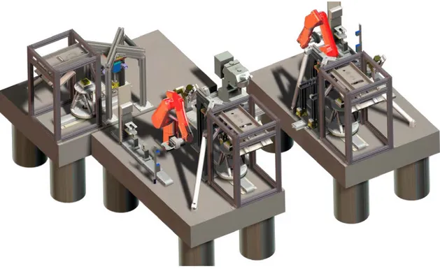
To evolve the SPO technology more efficiently, three representative mirror modules are being developed in parallel, for the inner,mid andouter radii of the baseline ATHENA design, each with its own individually optimised mandrel geometries, mirror plate sizes, stacking robots (see figure 3) and mirror module integration jigs. The challenges for each radial position are specific and different from those of the other radii. The inner mirror modules e.g. require strongly bent plates, with a bending radius of down to only 250 mm, implying thin mirror membranes and long mirror plates. The outermost mirror modules have very short mirror plates, which required the introduction of the ‘mother-plate’ concept, whereby several mirror plates are processed as one plate until the last moment, when it is cut into individual plates, in order to reduce edge effects. The progress made on each of the challenges is later, where appropriate, cross-fed to the other radii, contributing to the general improvement of the SPO technology.
These iterations and cross-feeding are embedded in an orchestrated plan, considering the evolving priorities whilst maintaining the final objectives constantly in view.
Figure 3. Work on three mirror module radii (inner/mid/outer) is progressing in parallel, using three independent stacking robots, each optimised for its radius. The challenges of the different radii are different, and the lessons learned are cross-fed to the other
radii.
3.
CURRENT PRIORITIES AND TECHNOLOGY DEVELOPMENT PLAN
A detailed technology development plan (TDP) has been developed for ATHENA with the ultimate end goal of ensuring the critical technologies reach TRL 5/6 [41] in time for the mission adoption in 2020. The generally annually updated TDP identifies intermediate targets and breaks the complex SPO development into manageable activities, which are largely funded by the ESA Science Programme and implemented under contract with industry and institutions.
The development of the SPO technology for ATHENA is synchronised to the mission schedule. All major reviews of the mission preparation also include a review of the technology status and investigate the progress of all related activities. Each of the individual activities has internal milestones and reviews, and the outputs are cross-linked to other activities as appropriate.
The current priorities of the SPO development are: 1. Improving the angular resolution
• Deposition of first and second plate
• Optimised die (tool used to pre-bend the plates and deposit them onto the mandrel or stack) design for different radii
• Refinement of the stacking recipe (pressure, duration) 2. Increasing production rates
• Mirror plate production automation • Coating mass production
2015 2016 2017 2018
Outer MM demo
Mid MM - Wolter
EQM Prep(CCN)
..
Inner MM demo
2019 2020 ATHENA Ph B1Outer MM EQM
Mid MM
EQM +ProdFealsInner MM EQM
All
SP#
T3
1Coated mr
ror plates
AIT1 CCN
L
AIT2 Inst. SelectT
CCNr
on Mech.'Process optimi ati4 (ccN)
MM facil'tydesign
Mirror Assem
Modellin ar
d simulation
Test facilities (Bessy, Panter)
Iy demo
X- ray /environmental facility
\1¢p /JSPOPerform nce/ Process Review Approved TDA tknowledge tMM deliver es tFacilities/ equipment MMproduce Qualte5ts
• Annealing of stacks (thermal treatment to increase the bond strength) • Shock and vibration testing on stack level
• Qualification and acceptance criteria definition
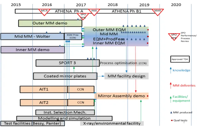
An overview of the ATHENA optics technology development plan, as per mid 2016, is given in figure 4.
Figure 4. The SPO Technology Development Plan (TDP) is synchronised with the system studies of the ATHENA mission. Development is progressing for three representative radii: inner-most, middle radius, and outer-most mirror modules, and addresses the performance, ruggedizing, industrialisation and accommodation aspects. Additionally test facilities and simulation work is covered in this TDP. Only major activities are shown.
The SPO development activities remain focused on five main areas: (1) improvement of the angular resolution of SPO mirror modules, (2) ruggedizing of Silicon Pore Optics, (3) demonstration of inner/outer radius mirror modules with the ATHENA focal length of 12 m, (4) preparation of the production of the large number of coated mirror modules, and (5) the integration of the mirror modules into the telescope structure. Further activities are addressing the modelling of the optics and the development and operation of test facilities.
In figure 4 the activities showing a black border are being implemented. The activities are inter-linked, with knowledge and equipment transfer and mirror module deliveries indicated by arrows. Following the SPO Performance and Process Review, the three parallel activities on the development of the inner/mid/outer mirror modules will be continued in a joint activity producing and testing the Engineering and Qualification Models (EQM) of the three representative radii. This activity will also demonstrate the feasibility to manufacture the number of mirror modules required for the ATHENA mission within the time allocated in the flight schedule.
The Silicon Pore Optics Ruggedisation and Testing 3 (SPORT3) activity is undertaking the ruggedizing of the mirror modules, and includes the required environmental testing to demonstrate the compatibility with the ATHENA environmental conditions. This activity will be continued with process optimisations accompanying the mirror module EQM activity.
A reliable supplier for the mirror plates has been established, and feeds the mirror module activities. In view of the large quantity of mirror plates required for the later implementation phase of the ATHENA mission, a second source of mirror plates is being developed, and the mirror plate coating is being industrialised. This activity will be followed by an activity designing the flight mirror module production facilities.
Two parallel activities are addressing the demanding task of integrating the mirror modules into the mirror structure. Each mirror module has to be accurately positioned and securely attached to the mirror support structure, employing isostatic mounting to ensure minimal distortion under the thermal and mechanical loads. The activities are undertaken by two independent industrial consortia, and employ different alignment methods. One is based on established heritage and uses direct UV alignment, and the other relies on opto-mechanical metrology and direct X-ray alignment. These activities will be followed by the Mirror Assembly demonstration, which will utilise mirror modules produced in the EQM activity.
Two instruments are to be alternatively served by the ATHENA optics, and a corresponding instrument selection mechanism is required. This mechanism is based on the implementation of a hexapod carrying the telescope mirror structure, allowing the optics to be pointed to either of the two instruments. This mechanism will also make possible the compensation of misalignments in orbit, e.g. caused by the launch loads or thermal distortions of the spacecraft. A prototype of this mechanism is being developed.
Mathematical modelling and test facility preparations, together with further activities not shown in figure 4, complement the technological preparation of the ATHENA optics. A new activity is currently being defined, which will address the preparation of the X-ray test facility to allow the verification and calibration of the complete ATHENA optics (X-ray/environmental facility). It is expected that specific environmental test capabilities will also be required, in particular to characterise the optics under different thermal conditions.
4. CONCLUSION
With technology spin-in from the semiconductor industry and employing a holistic design approach, an elegant but demanding X-ray optics technology is being developed to enable the ATHENA mission, fulfilling the traditionally conflicting requirements of providing a large effective area, good angular resolution and low mass.
The ATHENA optics technology development is following a detailed technology plan with a coordinated and iterative approach. The development is structured into technology development activities, which are contracted to industrial consortia and funded by ESA.
ACKNOWLEDGEMENTS
The authors would like to acknowledge the importance of the support by the many companies and institutions and individuals providing their excellent expertise and bringing in their heritage to manufacture the high quality optics, their components and tools required for their assembly and testing.
REFERENCES
[1] Ayre, M., et al, “ATHENA – System design and implementation for a next generation x-ray telescope”, Proc. of SPIE Vol. 9601, 96010L (2015)
[3] Nandra, P. et al, “ATHENA : The Advanced Telescope for High-Energy Astrophysics”, http://www.the-athena-x-ray-observatory.eu/
[4] Bavdaz, M. et al., "Progress at ESA on high-energy optics technologies", Proc. SPIE 5168, 136-147 (2004).
[5] Beijersbergen, M. et al., "Development of x-ray pore optics: novel high-resolution silicon millipore optics for XEUS and ultralow mass glass micropore optics for imaging and timing", Proc. SPIE 5539, 104-115 (2004).
[6] Beijersbergen, M. et al., "Silicon pore optics: novel lightweight high-resolution X-ray optics developed for XEUS", Proc. SPIE 5488, 868-874 (2004).
[7] Kraft, S. et al., "Development of modular high-performance pore optics for the XEUS x-ray telescope", Proc. SPIE 5900, 297-308 (2005).
[8] Günther, R. et al., "Production of silicon pore optics", Proc. SPIE 6266, 626619 (2006).
[9] Collon, M. J. et al., "Performance characterization of silicon pore optics", Proc. SPIE 6266, 62661T (2006).
[10] Collon, M. J. et al., "Metrology, integration, and performance verification of silicon pore optics in Wolter-I configuration", Proc. SPIE 6266, 626618 (2006).
[11] Graue, R. et al., "Assembling silicon pore optics into a modular structure", Proc. SPIE 6266, 62661U (2006). [12] Wallace, K. et al, “Silicon pore optics development”, Proc. SPIE 7437, 7437 (2009).
[13] Kampf, D. et al., “Optical bench elements (petals) for IXO”, Proc. SPIE, 7437 (2009). [14] Collon, M. J. et al, “Stacking of silicon pore optics for IXO”, Proc. SPIE, 7437 (2009).
[15] Ackermann, M et al, “Performance prediction and measurement of silicon pore optics”, Proc. SPIE, 7437 (2009). [16] Vacanti, G, et al., “Silicon pore optics for astrophysical missions”, Proc. SPIE, 7732, 77324O (2010).
[17] Collon, M. J. et al, “Stacking of Silicon Pore Optics for IXO”, Proc. SPIE 7732, 77321F (2010). [18] Bavdaz, M., “ESA optics technology preparation for IXO”, Proc. SPIE 7732, 77321E (2010).
[19] Wille, E, et al, “Mass Production of Silicon Pore Optics for IXO and ATHENA”, Proc. of SPIE 8147, 81470E1(2011) [20] Collon, M, et al, “Design, Fabrication, and Characterization of Silicon Pore Optics for ATHENA/IXO”, Proc. of SPIE
8147, 81470D1(2011)
[21] Bavdaz, M. et al., “ESA led ATHENA/IXO optics development status”, Proc. of SPIE 8147, 81470C1(2011) [22] Bavdaz, M, et al, “Silicon Pore Optics developments and status”, Proc. of SPIE 8443, 844329(2012)
[23] Ackermann, M, et al, “Novel applications of Silicon Pore Optics technology”, Proc. of SPIE 8443, 84430V(2012) [24] Bavdaz, M., et al, “X-ray optics developments at ESA”, Proc. of SPIE Vol. 8861, 88610L (2013)
[25] Collon, M., et al, “Aberration-free Silicon Pore X-ray Optics”, Proc. of SPIE Vol. 8861, 88610M (2013)
[26] Wille, E., et al, “Stray Light Baffling and Environmental Qualification of Silicon Pore Optics”, of SPIE Vol. 8861, 88611E (2013)
[27] Willingale, R. et al, “Science requirements and optimization of the silicon pore optics design for the ATHENA mirror”, Proc. of SPIE Vol. 9144, 91442E (2014)
[28] Bavdaz, M. et al, “Preparing the optics technology to observe the hot universe”, Proc. of SPIE Vol. 9144, 91442F (2014) [29] Collon, M. et al, “Making the ATHENA optics using Silicon Pore Optics”, Proc. of SPIE Vol. 9144, 91442G (2014) [30] Wille, E. et al, “Qualification of Silicon Pore Optics”, Proc. of SPIE Vol. 9144, 91442H (2014)
[31] Bavdaz, M. et al, “The ATHENA Optics”, Proc. of SPIE Vol. 9603, 96030J (2015)
[32] Collon, M. et al, “Silicon Pore Optics development for ATHENA”, Proc. of SPIE Vol. 9603, 96030K (2015)
[33] Wille, E. et al, “Silicon Pore Optics Mirror Modules for Inner and Outer Radii”, Proc. of SPIE Vol. 9603, 96030L (2015) [34] Vacanti, G., et al, “New ray-tracing capabilities for the development of Silicon Pore Optics”, Proc. of SPIE Vol. 9603,
96030G (2015)
[35] Della Monica Ferreira, D. et al., “Coating Optimisation for the ATHENA+ mission”, Proc. Of SPIE Vol.8861, 886112 (2013)
[36] Massahi S., et al, “Investigation of Photolithography Process on SPOs for the ATHENA Mission”, Proc. of SPIE Vol. 9603, 96030M (2015)
[37] Krumrey, M. et al, “X-ray pencil beam facility for optics characterization”, Proc. SPIE 7732, 77324O (2010).
[38] Freyberg, M. et al., "Potential of the PANTER x-ray test facility for calibration of instrumentation for XEUS", Proc. SPIE 6266, 62663H (2006).
[39] Burwitz, V., et al, “In focus measurements of IXO type optics using the new PANTER X-ray test facility extension”, Proc. of SPIE Vol. 8861, 88611J (2013)
[40] Krumrey, M. et al, “New X-ray parallel beam facility XPBF 2.0 for the characterization of silicon pore optics”, these proceedings (2016)
[41] ISO, “Space systems - Definition of the Technology Readiness Levels (TRLs) and their criteria of assessment”, ISO 16290, The International Organization for Standardization (2013)