Chapter 2
The prostheses
2.1. Definition
Before going any further in the investigation of the gait with prosthesis, it is necessary to define precisely what is a prosthesis. The prosthesis must first be defined as all the pieces and mechanism involved in the replacement of the member in a functional way as well as in an esthetical one. The esthetical part of the definition may seem futile, however it represents a great part of the quality of the prosthesis for the amputees, who want to have a life as normal as possible, and hide their handicap. There is thus lots of different kind of prosthesis (foot, ear and so on), but in the following investigation the knee prosthesis will be only consider. The amputees who are concerned by this prosthesis are thus the thigh amputees who have lost a part of their thigh.
2.2. History of the prosthesis
The prosthesis is a really old invention. Prosthetic care goes to the fifth Egyptian Dynasty (2750-2625 B.C.); archaeologists have unearthed the oldest known splint from that period. The earliest known reference to an artificial limb was made around 500 B.C., Herodotus wrote of a prisoner who escaped from his chains by cutting off his foot, which he replaced with a wooden substitute. The oldest known artificial limb, dating from 300 B.C., was a copper and wood leg unearthed at Capri, Italy in 1858. In 1529, French surgeon, Ambroise Pare introduced amputation as a life- saving measure in medicine. Soon after, Pare started developing prosthetic limbs in a scientific manner. In 1863, Dubois L Parmelee of New York City made an improvement to the attachment of artificial limbs. He fastened a body socket to the limb with atmospheric pressure and also with harness. He was not the first person to do so, but he was the first person to do so withsatisfactory results. In 1898, Dr. Vanghetti invented an artificial limb that could move with through muscle contraction. In 1946, a major advancement was made in the
attachment of lower limbs. A suction sock for the above-knee prosthesis was created at University of California (UC) at Berkeley. In 1975, Ysidro M. Martinez invention of a below-the-knee prosthesis avoided some of the problems associated with conventional artificial limbs. Martinez, an amputee himself, took a theoretical approach in his design. He did not attempt to replicate the natural limb with articulated joints in the ankle or foot which is seen by Martinez as causing poor gait. His prosthesis has a high centre of mass and is light in weight to facilitate acceleration and deceleration and reduce friction. The foot is considerably shorter to control acceleration forces, reducing the friction and pressure. More details can be found in [13].
2.3. The Knee prostheses made by Otto-Bock
By definition, the knee-prosthesis should replace the function of the knee and the lower leg. The action of the muscles should also be produced by the prosthesis in order to present a walking process as close from the natural gait as possible. However such action are not available on none of the prosthesis currently on the market. The function enabled by the prosthesis is thus only the bending of the leg. It is almost only a hinge linking the upper leg, which is the natural one of the amputee, with an artificial shin, which is most of the time only a bar.
The bending of the leg enable a gait without much effort. The amputee does not have to make his prosthesis leg have a movement much different from the one in a natural walk. On the contrary if his leg was completely straight, the amputee should have an unbalanced gait to make the prosthesis leg go before the other. The knee-prosthesis enable thus an almost human-like gait under normal circumstances, but as all the function of the knee are not available, some situations are letting the amputee alone with difficulties. The prosthesis fails to help the amputee to climb a stairs: no muscles can support the weight of the body during the transition phase in which the prosthetic leg is the only contact with the ground.
Nowadays the recognition of the life of the amputee is getting more public, as it is possible to see with the Handy sport more and more on television. The use of new
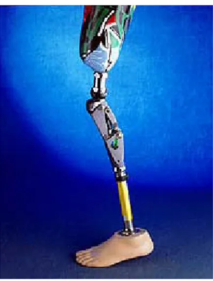
first quite simple and constituted by four bars. But then springs and dampers have been added. The new evolution is to integrate in the prosthesis electronics. The company Otto Bock Health Care GmbH has designed a new generation of prosthesis: the C-leg. The C-leg knee integrate a hydraulic system controlled by a micro-processor(fig.2.1).
Fig. 2-1: The C-leg controlled by a micro-processor
Two main configurations are programmed : the swinging phase and the stance phase. The micro-processor is provided fifty times each second with information through several captors which are measuring mainly the angle between the shin and the thigh, and the force applied on the foot. The micro-processor will then calculate the value of the damping and of the elasticity to enable a correct gait and applies them through servomotor. This electronic system is adaptable enough to enable the patient to have a normal life, because it will adapt itself to the requirement and activities of the patient. Moreover the standing position will be more comfortable, because a flexibility of the prosthetic leg is allowed, through the control of the position by the micro-processor.
The prosthesis that will be studied in the following report is the prosthesis 3R60, designed by the company Otto Bock Health care GmbH.
2.3.1. Description of the prostheses
The prosthesis 3R60(fig.2.2) is not electronically controlled, and is constituted only by mechanical parts. The unique characteristic of the 3R60 is its Ergonomically Balanced Stride (EBS*) from polycentric joint kinematics that provide variable stance phase stability.
Fig. 2-2: The prostheses 3R60
A special adjustable resistance provides up to 15° of cushioned stance flexion. Two axial forks connect the upper and lower joint section to one another and create a kinematic chain. A pivoting mount joins the lower joint section to the rear axial fork, which is also connected to the shock absorbing elements of the EBS unit. At heel strike, the proximal joint sections swing dorsally around the lower axis. The rubber bumper of the EBS unit is compressed as the pivoting mount rotates. This elastic flexion provides a “bouncy effect” and simultaneously increases stance phase stability. The joint is stable under weight bearing up to a maximum of 15° of knee flexion. Weight bearing and ambulation thus become more natural and more comfortable. The resistance of the EBS unit may be adjusted according to the weight and activity level of the patient. The hydraulic unit located between the axial forks controls swing phase. It prevents both excessive heel rise and terminal impact.. Another unique feature of this unit is that it
2.3.2. Kinematic properties of the prostheses
The movement
The 3R60 will enable the shin and the thigh to have respectable angles. A kinematic with 4 bars and some hinges has been chosen. In the picture 2.3 is showed how this kinematic enable to have the rotation movement of the shin around the thigh.
Fig. 2-3: Kinematic of the prostheses 3R60
The comfort of the gait
The reason why this phase is not comfortable on other prosthesis is because sometimes the shin catch up the thigh with a too high velocity. The blockade of the shin will cause a shock, and vibrations will be spreading all along the prosthesis and thus there will be friction at the contact between prosthesis and the patient thigh. Such friction have to be avoided, because it can hurt the patient on an already sensitive part of his leg. The prosthesis 3R60 is provided with an hydraulic system, that will prevent this issue.
Fig.2.4: The special element The stance phase
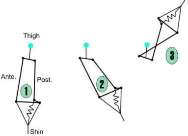
The company Otto Bock has designed a special feature to provide the patient with an extra security system during the stance phase. A new spring-damper element has been added in the system to secure the phase and to improve the comfort of walking. This element is showed in the picture 2.4. The prosthesis has a polycentrism system as already mentioned in the previous paragraph. The centres of rotation depend on the weight of the patient and more precisely of the charge that is loaded on the prosthesis. The picture 2.5 will present the cinematic under different conditions. The first graph represents the prosthesis without any load applied on it. The centre of rotation is nor far away from the prosthesis, the prosthesis can thus be working. On the second graph however the centre of rotation is far away, because the two parts that should be rotating are almost parallel. This is the stance phase corresponding to the straight position of a man. The change of the configuration is due to the weight of the body that has been applied on the prostheses.
This means when the prostheses is bearing the body, it can not bent and when not, then the prostheses can be working in a normal way because the security system is not active. The two phases are really differentiable, the prosthesis cannot unleash normal flexion, when it is in the stance phase, which could have caused the fall of the patient.
Fig.2.5: Polycentrism of the prostheses
The comfort
The system above is called E.B.S. and provides more than security. The change of the kinematic configuration is due to a damping-spring, which is represented in figure 2.5 (the green element in the prostheses). At each heel strike the shock should be transmitted in the prosthesis leg (which has no elasticity) to the patient leg. Such regular shock can irritate the leg and are obviously uncomfortable. The damping spring of the security designed system E.B.S. will with the prosthesis 3R60 absorb the shock and the vibrations during the heel strike. The prosthesis 3R60 has solve many issues about the comfort of walking and in the same time improve the security of the gait.