Facoltà di Ingegneria
Corso di Laurea Specialistica in
Ingegneria Elettronica
Tesi di Laurea
Definition and design
of a new communication protocol and interfaces
for data transmission
in High Energy Physics experiments
Relatori
Prof. Luca Fanucci
Ing. Sergio Saponara
Ing. Guido Magazzù
Candidato
Claudio Tongiani
INTRODUCTION ...4
1 THE FF-LYNX PROJECT ...6
1.1 Genesis of the project...6
1.1.1 High Energy Physics experiments ... 6
1.1.2 The Large Hadron Collider at CERN and its experiments ... 10
1.1.2.1 CMS ... 11
1.1.2.2 ATLAS... 14
1.1.3 Requirements of DAQ/TTC systems for HEP experiments ... 15
1.2 Purposes of the project...18
1.3 Methodology and design flow ...20
2 THE FF-LYNX PROTOCOL...23
2.1 General characteristics ...23
2.2 The THS channel ...25
2.2.1 TRG and HDR scheduling... 26
2.2.2 Synchronization... 27
2.2.3 The THS encoding... 29
2.2.3.1 Elements of coding theory ... 29
2.2.3.2 TRG/HDR/SYN encoding ... 34
2.2.3.3 TRG/HDR balanced encoding ... 37
2.3 The FF-LYNX frame ...38
2.3.1 The Frame Descriptor... 40
2.3.1.1 The H(12,7) encoding ... 40
2.3.2 Payload and label... 46
2.3.3 Trigger data frames... 47
2.4 Future protocol versions...48
2.5 Protocol validation ...50
2.5.1 Synchronization algorithm selection ... 52
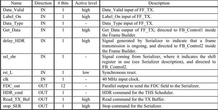
3 FF-LYNX INTERFACES...56 3.1 FF_TX...56 3.1.1 External specifications... 56 3.1.2 Internal architecture... 59 3.2 FF_RX...61 3.2.1 External specifications... 61 3.2.2 Internal architecture... 65
4 VHDL MODELING AND SIMULATION...67
4.1 General description of the model ...68
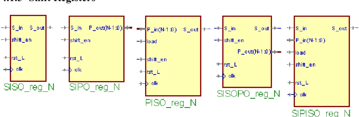
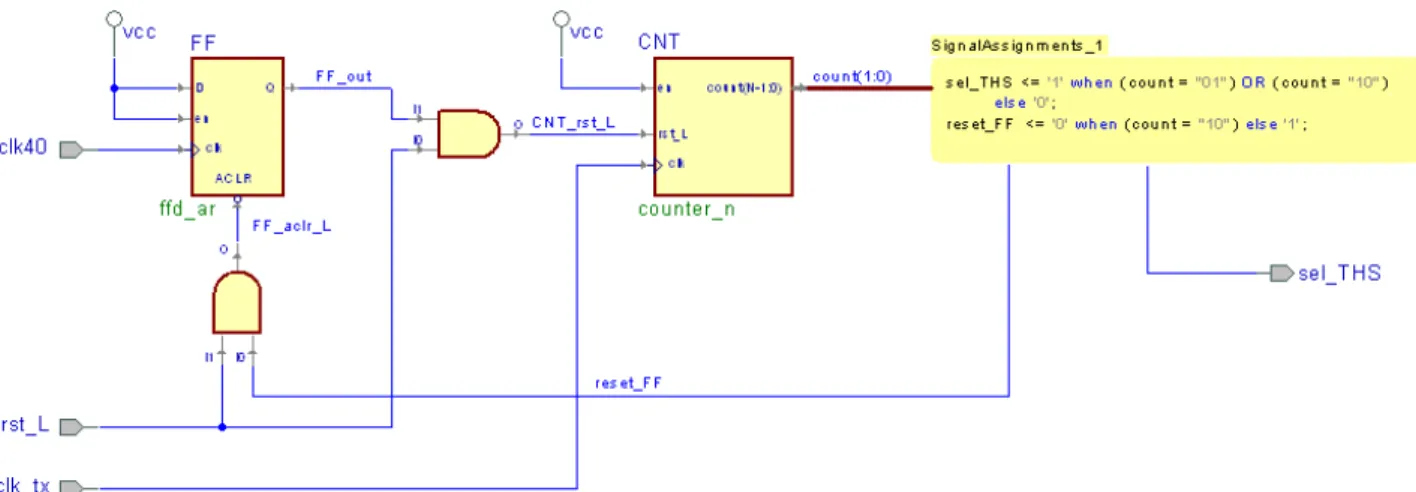
4.1.2 Counter_N ... 70 4.1.3 ffd ... 70 4.1.4 Register_N... 71 4.1.5 Shift Registers ... 72 4.2 FF_TX...73 4.2.1 TX Buffer ... 73 4.2.2 sel_THS Generator TX... 74 4.2.3 Frame Builder... 76 4.2.3.1 FB_Control1 ... 78 4.2.3.2 FB_Control2 ... 82 4.2.3.3 FD Encoder ... 86 4.2.4 THS Scheduler... 86 4.2.5 Serializer... 90 4.2.5.1 THS load controller... 93 4.2.5.2 THS command selector... 95 4.2.5.3 Pulse Shrinker ... 95 4.2.5.4 Ser_Control ... 97 4.3 FF_RX...104 4.3.1 Deserializer... 104 4.3.1.1 Des_control ... 108 4.3.2 THS Detector... 111 4.3.3 Synchronizer... 112 4.3.3.1 Clock Splitter ... 115 4.3.3.2 Sync Counter... 115 4.3.4 Frame Analyser... 118 4.3.4.1 FA_Control1 ... 120 4.3.4.2 FA_Control2 ... 124 4.3.4.3 FD Decoder... 126 4.3.5 sel_THS Generator RX... 127 4.3.6 TRG stretcher ... 128 4.3.7 RX Buffer ... 130 4.4 Test bench ...131 4.4.1 TX Host Emulator ... 132 4.4.2 RX Host Emulator ... 134 4.4.3 Comparison of files ... 135 4.4.4 Test results... 136 5 FPGA PROTOTYPING...138 5.1 FF-LYNX Emulator...138 5.2 Development board...139
5.3 FPGA synthesis of FF-LYNX interfaces...140
CONCLUSIONS AND FUTURE DEVELOPMENTS...142
Introduction
Particle physics, often referred to as High Energy Physics (HEP), is the branch of physics that studies the most basic constituents of matter, i.e. subatomic particles, and their interactions in order to answer key questions about nature and origin of the Universe and improve the understanding of the fundamental laws that regulate it. The main instruments for High Energy Physics are particle accelerators, complex machines that produce beams of particles and provide them with the high energies needed by High Energy Physics experiments, that consist in colliding particle beams and studying the results of the collisions using particle detectors that surround the interaction point. Most of the attention, in the world of particle physics, is nowadays focused on the Large Hadron Collider (LHC) at CERN (the European Organization for Nuclear Research) that is now the world’s largest and most powerful particle accelerator and promises, by means of collision energies never reached before, to make new particle events observable that could answer fundamental questions of nowadays physics, such as the existence of the Higgs boson, that could explain the origin of mass, and supersymmetric particles, related to dark matter and dark energy.
Current HEP experiments have very similar architectures with respect to systems for acquisition of data from sensors and for control and management of the detector. Signals generated by sensors in particle detection are handled by Front-End (FE) electronics embedded in the detectors and transferred to remote data acquisition (DAQ) systems, that are placed far away from the experiment’s area to keep them in an environment that is free from the intensive levels of radiation that is present in the proximities of the interaction point: typically the transfer is carried out by means of electrical links for a first stretch inside the detector, and then through optical links that allow to cover the long distances (hundred of meters) from the experiment’s area to the remote DAQ system, and provide the large bandwidth needed (up to tens of Gbit/s). The DAQ systems constantly receive a stream of data from a subset of the sensors which is used to detect significant events: if such an event is detected the DAQ system sends a trigger to the Front-End electronics which commands the start of a full-scale DAQ process from all the detectors: this way the very large amount of data generated in the detector is reduced to rates that can be handled by the readout system (a typical order of magnitude is hundreds of MB/s from each FE device), and only the interesting events are selected. A remote control system, also called TTC (Timing, Trigger and Control) system, manages trigger distribution and the configuration and monitoring processes in the Front-End electronics.
Also in future HEP experiment, such as the ones for the two-phase upgrade (in 2013 and 2018) of LHC that will lead to the so-called Super LHC, DAQ and TTC systems will have similar architectures, and therefore they will still share most of the requirements with respect to data rate, trigger latency, robustness against transmission errors and component failures, radiation hardness and power dissipation of hardware components; hence, common solutions for data transmission systems that can be shared and reused in several applicative contexts can minimize time, risks and effort for the development of new experiments. In particular, electrical serial links between Front-End electronics and Electrical to Optical Converters (EOCs) will be required; these links will have to cover a wide range of data rates from tenths of Mbit/s from each FE through intermediate stages of data concentration to one Gbit/s. The literature on electrical links is mostly about communications below one Mbit/s for configuration/control tasks, and standard protocols used in telecommunications, consumer electronics and automotive industry are not suitable for this field of application, failing to satisfy the stringent requirements above mentioned especially about radiation hardness and trigger latency.
Moving from these considerations, the FF-LYNX (Fast and Flexible links) project was started in January 2009 by a collaboration between INFN-PI (Italian National Institute for Nuclear Physics, division of Pisa) and the Department of Information Engineering (DII_IET) of the University of Pisa, with the aim of defining a new serial communication protocol for integrated distribution of TTC signals and Data Acquisition, satisfying the typical requirements of HEP applications and
providing flexibility for its adaptation to different scenarios, and of its implementation in radiation-tolerant, low power interfaces. The work presented in this thesis constituted a phase of the FF-LYNX project working plan and was carried out at the Pisa division of INFN: in particular, it dealt with the definition of a first version of the FF-LYNX protocol and the design of hardware transmitter and receiver interfaces implementing it. A description of the contents of this thesis follows.
In chapter 1 the FF-LYNX project is presented: after a brief description of High Energy Physics experiments and typical requirements of data transmission systems for this field of application, the purposes of the project are presented and the methodology defined for the project work is outlined.
Chapter 2 describes the FF-LYNX protocol, and in particular the version 1 that was defined and implemented in this thesis work: the basic issues about trigger and data transmission that were considered in the definition of this version of the protocol are outlined, as well as the solutions that were adopted to address these issues. Also, new features that are foreseen to be included in future versions of the protocol are briefly described, and finally the results of simulations in a high-level model of the link, intended to estimate various aspects of the protocol performance, are presented.
Chapter 3 illustrates the architecture that was defined for the interfaces implementing the FF-LYNX protocol version 1: a functional description of input and output ports of the FF-FF-LYNX Transmitter and Receiver is given first, and then their internal functional architecture is outlined.
Chapter 4 presents the VHDL models of the transmitter and receiver blocks that was created in the design phase of the FF-LYNX interfaces implementing the protocol version 1.The functionality of each component is described in detail also showing the results of VHDL simulations on it. Finally, the structure and the operation of the VHDL test bench built to test the functionality of the complete transmitter-receiver system are described, and results of simulations on it are reported.
In chapter 5 an FPGA based emulator for the FF-LYNX transmitter-receiver system, foreseen as the final result for the FF-LYNX project first year of activity, is outlined in its functional architecture, and the development board chosen for its implementation is briefly described. Finally, the results of preliminary synthesis trials of the designed TX and RX blocks onto the target FPGA are reported.
This thesis ends with the exposition of conclusions about the work that has been done, and the outlining of next developments that are foreseen in the future activity for the FF-LYNX project.
1 The FF-LYNX project
In this chapter the FF-LYNX project is presented. The FF-LYNX project, approved and funded by INFN V Commission, started in January 2009 and, in a three-year foreseen activity, aims at the design of an integrated and scalable system for data acquisition and control in High Energy Physics experiments. To this end, the definition of a novel communication protocol is foreseen, as well as its implementation in radiation tolerant and low power interfaces to be provided to ASIC designers for inclusion in their systems.
The project genesis is outlined first in section 1.1, with a brief introduction to the field of High Energy Physics experiments and the description of the requirement for data transmission systems in this area of application; then the goals of the project are illustrated in section 1.2, and finally section 1.3 presents the methodology that was settled for the project activities and the design flow.
1.1 Genesis of the project
The FF-LYNX project was born from the experience of INFN in the field of High Energy Physics (HEP) experiments and collaborations with the most important research centers for particle physics (such as CERN, Fermilab, etc.) and in particular from considerations about the opportunity of a research and development activity focused on the definition of an innovative data transmission system that could meet the typical requirements of HEP scenarios, intended to become a new flexible standard for application to different experiments thus minimizing development costs and efforts. With this aim, the FF-LYNX project was started as a collaboration between the experience of INFN in design and development of Silicon and Gas detectors and radiation tolerant Integrated Circuits, and the experience of DII-IET in communication protocols and radiation tolerant interfaces for space applications.
1.1.1 High Energy Physics experiments
Particle physics is the branch of physics that studies the most basic constituents of matter and
their interactions. Modern particle physics research is focused on subatomic particles, i.e. particles with dimensions and mass smaller than atoms, including atomic constituents such as electrons, protons and neutrons and particles produced by radiative and scattering processes, such as photons, neutrinos and muons. Since many elementary particles do not occur under normal circumstances in nature, to allow their study they are created and detected by means of high energy collisions of other particles in particle accelerators: therefore, particle physics is often referred to as High Energy
Physics (HEP). The purpose of particle physics is to investigate the fundamentals of matter in order
to address unanswered key questions about nature and origin of the Universe, such as symmetries in physical laws, the origin of mass, the nature of dark matter and dark energy, possible existence of extra dimensions and so on; the final, ambitious objective would be the creation of a general theoretical model that is able to describe and explain all physical phenomena in an unified and coherent vision.
The main instruments for High Energy Physics are therefore particle accelerators, large and complex machines that produce beams of particles and provide them with the high energies needed for HEP experiments. Accelerators typically employ electric fields to increase kinetic energy of particles and magnetic fields to bend and focus the beam, which is then collided against a fixed target or with another particle beam: the high energy collision produces the new particles and events that must be detected and studied. Beside the use in particle physics, the applications of accelerators nowadays span from industry (e.g. ion implantation in electronic circuits) to medicine
(radiotherapy), with different ranges of energy for the different fields application. Current accelerators for High Energy Physics work in the GeV and TeV energy range (referring to the energy provided to particle beams) and typically treat beams of electrons, hadrons1 and heavy atomic nuclei; the structure can be linear (LINAC, LINear ACcelerator), with the particle beam traveling from one end to the other and colliding against a fixed target, or circular (cyclotrons, synchrotrons), with the beams traveling repeatedly around a ring, gaining more energy at every loop and colliding with other beams running in opposite direction (Fig. 1.1).
The major research centers for High Energy Physics nowadays include, among the others:
- The European Organization for Nuclear Research (CERN), located near Geneva, Switzerland: its main facilities included LEP (Large Electron Positron collider), which was dismantled in 2001 and substituted with LHC (Large Hadron Collider) that is now the world’s most energetic accelerator;
- DESY (Deutsches Elektronen Synchrotron), located in Hamburg, Germany: its main structure is HERA, which collides electrons or positrons and protons;
- the Fermi National Accelerator Laboratory (Fermilab), located near Chicago, USA: its main facility is the Tevatron, which collides protons and antiprotons;
Fig. 1.1 – Aerial view of two particle accelerators for HEP experiments: (a) the Stanford Linear Accelerator Center
(SLAC), an example of LINAC; (b) the Tevatron at Fermilab, that is an example of circular accelerator.
1 Hadrons are the subnuclear particles that are subject to the strong force, and are constituted by quarks. The family of
hadrons is then divided in two subsets: baryons, comprising neutrons and protons, and mesons, including pions and kaons.
- the Stanford Linear Accelerator Center (SLAC), located near Palo Alto, USA: it hosts the longest linear accelerator in the world, colliding electrons and positrons;
- the INFN (Istituto Nazionale di Fisica Nuleare) center in Frascati, Italy, that hosts DAΦNE (Double Annular ring for Nice Experiments) a circular accelerator for the collision of electrons and positrons.
High Energy Physics experiments thus consist in colliding particle beams in accelerators and studying the results of the collisions by means of particle detectors that surround the interaction point. Particle detectors are devices used to track and identify high-energy particles produced in collisions, also measuring their attributes like momentum, charge and mass. A particle detector is typically made up of different layers of sub-detectors, each specialized in revealing and measuring different particles and properties of particles: normally the innermost layer (i.e. the nearest to the interaction point) is the tracking device, that has the task of revealing the paths of electrically charged particles through the trails they leave behind; in the outer layers calorimeters are typically placed, that measure the energy lost by particles that go through them. To help identify the particles produced in the collisions, the detector usually includes a magnetic field that bends the path of charged particles: from the curvature of the path, it is possible to calculate the particle momentum which helps in identifying its type. Particles with very high momentum travel in almost straight lines, whereas those with low momentum move forward in tight spirals.
To record and analyze events produced by collisions in an experiment, information about particles detected by sensors in the detector are converted into electric signals, which are then collected by dedicated electronic components embedded in the detector and located in close contact with the sensors themselves: these devices, usually called Front-End (FE) electronics, deal with the proper conditioning of signals (e.g. amplification, shaping, buffering, analog to digital conversion) and their transmission to remote data acquisition systems that perform data analysis and storage. However, some means is needed to reduce the amount of data that must be transferred from the detector to the remote system, that is extremely large in every HEP experiment. In fact, to increase the probability of occurrence of rare, interesting events, the number of interactions per second is made very high (a typical order of magnitude is billions of particle interactions per second); a measure of collision rate is the so-called luminosity, which is usually expressed in cm-2 s-1 and for a two-beam collider is defined as the number of particles per second in one beam multiplied by the number of collisions per unit area in the other beam at the crossing point. Collision rates of this order of magnitude produce amounts of raw data that range from tens of terabyte to a petabyte per second, which is beyond the possibility of any data acquisition and storage system. Therefore, since the interesting events are a very small fraction of the total, the total amount of data is filtered by means of a trigger system: raw data are temporarily buffered in the FE electronics while a small amount of key information is used by trigger processors (located at various hierarchical level inside the detector and in the remote elaboration center) to perform a fast, approximate calculation and identify significant events: the result of this processing is a trigger signal that is sent back to FE electronics to command a data readout, i.e. the transferring of a selection of the buffered data towards the remote system. This way, the amount of data to be transferred is reduced to rates that can be handled by the readout system (a typical order of magnitude is hundreds of MB/s from each FE device), and only the interesting events are selected.
Fig. 1.2 – Typical architecture of the control and readout system for a HEP experiment.
Signals generated by the interaction with sensors of particles produced in the beam collisions are handled by Front-End electronics embedded in the detectors and transferred to remote data acquisition (DAQ) systems, that are placed far away from the experiment area to keep them in an environment that is free from the intensive levels of radiation that are present in the proximities of the interaction point: typically the transfer is carried out by means of electrical links for a first stretch inside the detector, and then through optical links that allow to cover the long distances (hundred of meters) from the experiment area to the remote DAQ system, and provide the large bandwidth needed (up to tens of Gbit/s). A subset of the transferred data is used to perform trigger calculation, and the generated trigger command is sent back to FE electronics along with timing (clock) and control signals by a remote control system, also called TTC (Timing, Trigger and Control) system, that manages the configuration and monitoring processes in the Front-End electronics.
High Energy Physics experiments constitute a very challenging application for electronics, since the equipment must deal with large amounts of data and high data rates, with tight timing and data integrity constraints and operate in an environment that is intrinsically hostile due to the high levels of radiation. Typical requirements for detector electronics and data transmission links in a HEP experiment are:
- radiation hardness: electronic devices and systems must tolerate high levels of ionizing radiations and the associated Total Dose Effects (e.g. threshold voltage drift and sub-threshold current increase in MOS devices) and Single Event Effects (e.g. Single Event Upset in flip-flops and SRAM cells);
- small size: the space available for devices and cabling inside a particle detector is usually very limited due to the large amount of different components (readout and control systems, cooling systems, mechanical structures and so on) that must be integrated in a small area around the interaction point; additionally, bulky equipments are undesired because any non-sensor material interferes with the measure by deflecting and absorbing the particles that must be detected (the amount of material surrounding the interaction point, characterized with the radiation thickness of each component/layer, is usually referred to as material budget);
- low power dissipation: due to the high concentration of electronic equipment inside the detector, power density is a major issue because it dictates the cooling requirements; cooling system is a critical aspect in HEP experiments because it complicates the material budget and the mechanical requirements;
- constant trigger latency: the trigger signal must be delivered to all Front-End devices with a fixed and known latency, to command the readout of selected data thus allowing precise reconstruction of significant events;
- capability of handling high data rates: readout electronics must be able to elaborate and transfer large amount of data in a limited time to allow a continuous data flow during the running of the experiment, with minimal loss of information; for the same reason, adequately high bandwidth in electrical and optical links are required;
- data integrity: appropriate methods must be employed in transmission links to protect data against transmission errors, and in storage elements to deal with data corruption due to radiation.
1.1.2 The Large Hadron Collider at CERN and its experiments
The Large Hadron Collider (LHC) at CERN is the world’s largest and most powerful particle accelerator. It is a circular structure of 27 km of circumference, located in an underground tunnel (100 m of average depth) near Geneva, Switzerland. It is constituted by two beam pipes, kept at ultrahigh vacuum, carrying two separate particle beams that travel in opposite directions. They are guided around the accelerator ring by a strong magnetic field, achieved using over 1600 superconducting electromagnets operating at a temperature of ‑271°C, that generate a magnetic field of about 8 Tesla.
LHC accelerates beams of protons and heavy ions (lead nuclei) and make them collide in four points of the accelerator ring, where large cavities are built around the tunnel to house the detectors of the LHC experiments; the rate of collisions is 40 millions per second, and hence 40 MHz is the frequency of the LHC master clock that synchronizes all the detectors. The energy of proton beams is 7 TeV for each particle, leading to a collision energy of 14 TeV which is the highest level ever reached in a laboratory; lead nuclei are accelerated to an energy of 2.7 TeV per nucleon. The design luminosity is 1034 cm-2 s-1 for protons.
The goal of LHC is to observe, by means of collision energies never reached before, new particle events that could answer most of the key questions of nowadays physics: in particular, experimental evidences are expected for the existence of the Higgs boson, that is theorized as the explanation to the origin of mass, and supersymmetric particles, that could clarify the nature of dark matter and dark energy.
LHC hosts six experiments: A Large Ion Collider Experiment (ALICE), A Toroidal LHC ApparatuS (ATLAS), the Compact Muon Solenoid (CMS), the Large Hadron Collider beauty (LHCb), the Large Hadron Collider forward (LHCf) and the TOTal cross section, elastic scattering and diffraction dissociation Measurement (TOTEM). The two larger experiments, ATLAS and CMS, are based on general-purpose detectors and are designed to investigate the largest range of physics possible. Two medium-size experiments, ALICE and LHCb, have specialized detectors for analyzing the LHC collisions in relation to specific phenomena. ATLAS, CMS, ALICE and LHCb detectors are installed in four huge underground caverns located around the beam crossing points of the LHC (Fig. 1.3). TOTEM and LHCf experiments are smaller in size, and are positioned near the CMS detector and the ATLAS detector, respectively.
Fig. 1.3 – The LHC complex and its four main experimental points. Pb and p denote the linear accelerators that generate
the ion and proton beams, which are then injected into the preaccelerators PS and SPS and finally into the main ring.
LHC operation was started for a first test beam circulation on 10 September 2008, but was then stopped few days later due to a severe fault in a superconducting magnet; after repairs and addition of supplementary safety features, the new turn-on is scheduled for November 2009. However, a two-phase luminosity upgrade for the accelerator is already planned, to increase the probability of observing rare events and improve the measurement precision: the upgraded accelerator will be called Super LHC (SLHC) and will have a luminosity increase by a factor of 2-3 for phase I, planned for 2013, and by a factor of 10 for phase II in 2018, reaching the value of 1035 cm-2 s-1 [1]. The consequently larger rate of events to be detected and the resulting larger amount of data to be handled will impact the detectors, which will have to be upgraded as well.
The work of requirement analysis inside the FF-LYNX project focused on the two main experiments at LHC: CMS and ATLAS, that are briefly described in the following sections.
1.1.2.1 CMS
The Compact Muon Solenoid (CMS) experiment uses a general-purpose detector to investigate a wide range of physics, including the search for the Higgs boson, extra dimensions, and supersymmetric particles. It is located in an underground cavern at Cessy in France, close to the Swiss border and Geneva.
The experimental apparatus is 21 m long, 15 m wide and 15 m high, and comprises different kinds of detectors laid out in concentric layers around the beam pipe, where the collision point is located (Fig. 1.4). From the interaction point to the outside, these detectors are:
- the tracker, a silicon detector that reveals the trajectories of charged particles;
- the electromagnetic calorimeter (ECAL), made up of lead tungstate sensors that measure the energies of electrons and photons;
- the hadronic calorimeter (HCAL), that has the task of measuring the energy of hadrons produced in each event: it is composed of alternating layers of absorbing materials and fluorescent “scintillator” materials;
- the muon chambers, for the detection of muons.
The detecting devices are enclosed inside a huge solenoid magnet that has the form of a cylindrical coil of superconducting cable and generates a magnetic field of 4 Tesla. The magnetic field is confined by a steel 'yoke' that forms the bulk of the detector weight of 12500 tons. As in most HEP experiment, the magnet is an essential part of the experimental apparatus, since the bending of the particle trajectory in the magnetic field allows to measure the momentum of a particle by tracing of its path.
Fig. 1.4 – The experimental apparatus of CMS.
At full operation, about one billion proton-proton interactions will take place every second inside the CMS detector. To allow data storage and processing, the event rate must be drastically reduced selecting only the potentially interesting events: this task is performed by the trigger system, that carries out the reduction in two steps called Level-1 Trigger (L1T) and High-Level Trigger (HLT). The Level-1 Trigger consists of custom-designed electronics that use coarsely segmented data from the calorimeters and the muon system, while holding the high-resolution data in pipelined memories in the Front-End electronics; the L1T calculation is carried out in about 1 μs, and reduces the event rate from the original 1 GHz to some tens of kHz: the design output rate limit of the L1 trigger is 100 kHz. The readout data of events that pass the L1T filter are sent is sent over fiber-optic links to the High Level Trigger, which is a software system implemented in a farm of commercial processors. The HLT has access to the complete read-out data and can therefore perform complex calculations to select specially interesting events, thus reducing the event rate to the final value of about 100 per second.
For requirement analysis our attention focused on the CMS tracker system, that is the detector with highest data flow rates being the innermost layer of the CMS apparatus. The tracker is made up of two sub-systems: a pixel detector, with three cylindrical layers located in the central section of the CMS detector around the beam pipe (the so called barrel), at radii between 4.4 cm and 10.2 cm; and a silicon strip tracker with 10 barrel detection layers extending outwards to a radius of 1.1 m. Each system is completed by endcaps which consist of 2 disks in the pixel detector and 3 plus 9 disks in the strip tracker on each side of the barrel.
The pixel detector is composed of several silicon sensor plates, segmented in 150 μm x 150 μm
sensitive elements (the pixels): each pixel consists in a reverse-biased p-n junction, that reveals the passage of charged particles by generating an electric current. The sensor signal is collected and handled by a silicon Read-Out Chip (ROC), bump-bonded to the pixel sensor (Fig. 1.5).
Fig. 1.5 – Structure of a CMS Pixel Detector.
Each sensor plate is mounted on a module, together with ROCs and a printed board that hosts circuits for monitoring voltage, current and temperature, for clock synchronization and trigger decoding, for concentrating data to be sent to the remote DAQ system. Data transmission is made on electrical links from each module to electro-optic conversion units (EOC) that are located at the end of the barrel, and on optical links from EOCs to the remote data gathering system. The central TTC system sends trigger and clock through optical links to distribution devices, that in turn deliver them to Front End modules through electrical links.
The strip detector has a structure that is similar to the pixel detector, but the silicon sensor plates are here segmented in thin strips (10 cm x180 μm in the inner four layers, and 25 cm x 180 μm in
the remaining six layers). The charge on each microstrip is read out and amplified by an Analogue Pipeline Voltage (APV25) chip. Four or six such chips are housed within a “hybrid”, which also contains electronics to monitor key sensor information, such as temperature, and provide timing information in order to match “hits” with collisions. The APV25 stores the signals in a memory for several microseconds and then processes them before sending to a EOC unit, from which data are sent to the remote DAQ system through optical fibers.
In both pixel and strip detectors, when a Front-End circuit receives a trigger signal from the centralized control system, the stored samples corresponding to the triggered event are serialized and sent to the concentrator, and from here to the optical transmitter. Currently this readout process is partially analog: readout data are stored in Front-End chips, concentrated and transmitted to a first stage of collection systems in analog form, and only subsequently they are digitized, processed and transmitted to the remote elaboration center. Analog readout data transmission is serial and synchronous with the 40 MHz LHC clock. For example, a ROC in the pixel detector transmits the data relative to a single “hit” (i.e. a pixel being hit by a particle), comprising the pixel address and the hit amplitude, in six successive 40 MHz clock cycles with an analog signal that can assume one of 6 different levels at each cycle. When digitized, the data for a pixel hit in a ROC correspond to 23 bits [5][6]. Considering then the occupancy, i.e. the probability for a channel to generate a significant event in correspondence to a trigger command, that is currently about 5.4 hits/ROC at each trigger event [6], we can estimate the readout data rate from each ROC in 23 bit x 5.4 x 100 kHz = 12.42 Mbit/s. Considering then the occupancy for a 16-ROC module, that is around 6.5 hit ROCs per module [6], we have a data rate from each module that is estimable as 6.5 x 12.42 Mbit/s = 80.73 Mbit/s.
The analog readout scheme was chosen mainly for resolution reasons, since the availability of an analog measure of hit amplitudes in pixel and strips permits, in case of charge sharing between adjacent sensor elements, interpolation techniques that in turn increase position resolution [9]; also, material budget is reduced as the analogue to digital conversion and its power needs are shifted out
of the tracker volume. However, in real operation the analog readout proved to have unsatisfactory performance mainly due to signal degradation in the readout chain and temperature sensitiveness of analog to optical converters [10]. This fact, together with the need for higher transmission speed to handle the larger data rate that will result from luminosity increase, dictates the switch to a fully digital readout scheme for the LHC upgrade, already in phase I. Considering again the case of the CMS pixel detector, for the phase I upgrade an increase factor of about 3 is foreseen for data rates from ROCs and from modules [6], leading to foresee a 160 Mbit/s digital link from each ROC to the data concentrator in the module, and a 320 Mbit/s digital link from each module to the EOC unit [6]. Similar requirements will show up for the strip detector.
1.1.2.2 ATLAS
ATLAS is the other general-purpose detector at the LHC; it is located in an underground cavern at Meyrn, near Geneva. It has the same physics goals as CMS, recording similar sets of measurements on the particles created in the collisions: their paths, energies, and their identities; however, the two experiments have adopted different technical solutions and designs for their detectors' magnet systems. The comparison of the results of the two experiments will be important for cross-confirmation of new discoveries.
The experimental apparatus is 46 m long, 25 m high and 25 m wide and is based, similarly to CMS, on a large superconductive magnet generating a magnetic field of 2 Tesla. Integrated with the magnet, the following concentric layers of detectors are displaced around the beam pipe (Fig. 1.6), listed here from the interaction point to the outside:
- the inner tracker, that measures the momentum of each charged particle;
- the electromagnetic and hadronic calorimeters, that measure the energies carried by the particles;
- the muon spectrometer, that identifies and measures muons.
Fig. 1.6 – The ATLAS detector.
The inner tracker is made up of three parts: the Pixel Detector, the Semi-Conductor Tracker (SCT) and the Transition Radiation Tracker (TRT). The Pixel Detector is the innermost part of the detector, and consists of 250 µm thick silicon sensors divided in 50 μm x 400 μm pixels and
distributed in modules; each module contains 16 readout chips and other electronic components. The SCT is the middle component of the inner detector: it is similar in concept and function to the Pixel Detector but with long, narrow silicon strips (80 μm x 12.6 cm) rather than small pixels,
making coverage of a larger area practical. The TRT, the outermost component of the inner detector, is a combination of a straw tracker and a transition radiation detector. The detecting elements are drift tubes (straws), filled with gas that becomes ionized when a charged particle passes through. Between the straws, materials with widely varying indices of refraction cause ultra-relativistic charged particles to produce transition radiation and leave much stronger signals in some straws.
The detector generates about 25 Mbytes of raw data per event, that multiplied for 40 million beam crossings per second give a total of 1 petabyte/s of raw data. The trigger system, structured in two levels, uses simple information to identify, in real time, the most interesting events to retain for detailed analysis. The first-level (LVL1) trigger works on a subset of information from the calorimeter and muon detectors. It requires about 2 μs to reach its decision, including the propagation delays on cables between the detector and the underground counting room where the trigger logic is housed. All of the information from the detector must be stored in pipeline memories until the LVL1 decision is available.. After the first-level trigger, about 100,000 events per second have been selected. The LVL2 trigger refines the selection of candidate objects, using full-granularity information from all detectors, including the inner tracker which is not used at LVL1. In this way, the rate can be reduced to about 1kHz.
The collection and readout of sensor data and the distribution of TTC signals are done with modalities and features that are similar to the ones in the CMS detector, and therefore also the requirements of data transmission systems about speed, radiation hardness, material budget and so on are similar, and will be similar for the LHC upgrade.
1.1.3 Requirements of DAQ/TTC systems for HEP experiments
From the scenario depicted in the preceding sections clearly appears that most High Energy Physics experiments, although different for the adopted technologic solution and implementative choices, share basic architectures and operating principles, and have similar requirements for the Data Acquisition and TTC systems; and the same will be in the near future. These requirements can be summarized in the following way, analyzing the different aspects of data readout and control processes.
- Data readout. Data collected from sensors by Front-End electronics must be transferred to the remote acquisition and elaboration system in response to trigger signals, that command data readout; this direction of data transfer is usually called uplink. The links that operate the transmission of readout data must provide a bandwidth that is adequate to the expected data rate, in order to minimize data losses due to buffer overflows and situations of busy data transfer systems. Usually data from different readout circuits are then gathered by a data concentrator inside a module, to allow their multiplexing to only one or two high-bandwidth links per module thus reducing the total number and length of cablings. The values required for link speed commonly range from 40 Mbit/s to 160 Mbit/s for the links between single readout chips to the data concentrator inside a module, and from 160 Mbit/s to about one Gbit/s for the links departing from each module. Packets of readout data must also be characterized with timing specifications in order to make their association to specific events possible by the elaboration system: typically a “time stamp” (i.e. a binary word whose value specifies a timing information) is attached to each data packet to associate it to a specific trigger command, and later in the readout chain the so called event building process is performed by grouping together all the data with a same time stamp thus reconstructing the physics event sensed by the detector.
- Trigger system. Trigger commands have to be transmitted from the central elaboration system to the Front-End circuits (downlink direction) with two fundamental requisites: the number of triggers that are lost due to transmission errors or other malfunctions must be minimum (possibly zero), and the latency of each trigger command from the central system to
each Front-End circuit must be fixed and known, in order to allow the correct time stamping of readout data and thus the correct reconstruction of events. These constraints must be fulfilled through a trigger transmission scheme that guarantees particular properties of high priority and error protection to the trigger signal; at the same time, however, this scheme must allow the transmission of triggers that are close in time up to a limit foreseen by the experiment: for example, the minimum interval between two consecutive triggers in the CMS and ATLAS experiment is respectively 3 and 5 cycles of the 40 MHz clock [11][13].
In the uplink, trigger data (i.e. the information from a subset of sensors that is used for trigger calculation) must be transmitted; the requirements here are again fixed latency and high bandwidth: for example, in the CMS upgrade it is foreseen that data from the microstip tracker will participate to the L1 trigger generation, with data rates that are foreseen to be in the range 40-120 Mbit/s from each FE ASIC and up to about one Gbit/s from each module [14].
- Timing and control system. The master clock of the experiment (e.g. the 40 MHz accelerator clock for the LHC experiments) must be delivered to all Front End circuits with controlled skew, in order to synchronize the detectors with the beam crossings. The downlink has also to transmit so called “slow control” commands to control and configure Front End devices; here the link speed requirements are more relaxed, with 40 Mbit/s being an adequate value for most cases. Currently, slow control is performed on dedicated links with custom or commercial protocols such as I2C [5], and a dedicated uplink is used for monitoring and response data from FE to the central control system.
- Error control. Critical data must be protected against transmission errors, that can arise from noise in the transmission lines and from Single Event Effects affecting the decision devices (e.g. photodiodes at the end of optical links): the environment of HEP experiment is particularly critical under this point of view. Transmission errors can occur in single events or in bursts, due to jets of particles hitting the lines. Error control coding scheme therefore must be adopted to limit data losses. The most critical signal under this point of view is the trigger, because a trigger command not reaching a FE circuit due to corruption means the loss of readout data that is associated to a potentially interesting event.
- Radiation hardness. Having to operate for years in an extremely radiation-full environment, all the electronic components must tolerate high levels of ionizing radiations (up to tens of Mrad [11]) and the associated Total Dose Effects and Single Event Effects without major malfunctions. Electronic systems hence must be designed and realized with proper rad-hard techniques and technologies, and submitted to irradiation tests.
- Material budget. The amount of non-sensor material (mechanical structures, cablings, cooling systems, etc.) inside the detector is a major concern in any HEP experiment, because it absorbs and deflects particles interfering with the measurement. The material budget is usually analyzed in detail for each component of the system, and for each part it is expressed as X/X0, i.e. the thickness of the material in units of its radiation length2 X0. For data
transmission systems the desirable thing is to reduce the number of physical links as much as possible, thus alleviating also the problem of fitting the required cabling in the limited space available inside the detector. Some ways to achieve this are the integration of more services (timing and trigger distribution, data transmission, etc.) on the same links, the use of serial transmission schemes rather than parallel ones, and the concentration of data streams from more sources (FE circuits) into few, high-bandwidth physical links. In some cases, the number of available cables is strictly limited due to available space constraints, and this poses the most stringent requirement for data transmission systems: for example, in the CMS upgrade for 2013 the number of pixel modules will be increased from 784 to1216 but only the existing fibers can be used due to space limitation [6]; therefore, just one fiber per module will be employed (currently there are 2 fibers from each module in the first two barrel layers of the
2 The radiation length of a material is the mean path length required to reduce the energy of relativistic charged
pixel detector) and the bandwidth of the link departing from each module must be increased to 320 MHz.
- Power dissipation. Power dissipation of electronics inside the detector is closely related to material budget, and it must be minimized mainly to relieve the requirements for power distribution and cooling system, that typically contributes to the overall material budget for the most part. In general, high-power consuming parts should be placed as farther as possible from the interaction point in order to minimize the cooling cabling in the center of the detector. As for data transmission systems, in current experiments typical values of power dissipation range from some mW to 10 mW per channel for electrical links from FE circuits to EOCs, and up to some watts per channel for optical links [15].
The FF-LYNX project moved from the analysis of these requirements, performed in close collaboration with physicists and engineers involved in the design of future detectors and Front-End electronics, and aims at the definition and implementation of innovative data transmission systems that could meet the common requirements of DAQ and TTC systems for HEP experiments, offering at the same time the necessary degree of flexibility to make the system adaptable to the specific needs and conditions of the different applications. Indeed, common solutions that can be shared and reused in several applicative contexts can maximize performance (allowing the observation of new physical phenomena) and minimize time, risks and effort for the development of new experiments. Besides, it was noted in the previous sections that most HEP experiments, for example ATLAS and CMS at LHC, and different components of the detector inside a single experiment (e.g. the pixel tracker and the microstrip tracker) share basic requirements and architectures; nevertheless, the groups of physicists and engineers that carried out the development of each experiment and are involved in the design of future upgrades appear in most cases as separate communities with little coordination, multiplying efforts while working on similar issues. Instead, a key lesson from the past ten years of activity in the design and construction of the large experiments for the LHC is that the use of common solutions for different detectors and experiments reduces efforts, resources and risks.
In particular, our attention focused on flexible electrical links, possibly integrating DAQ and TTC functions in a single protocol and relative communication interfaces: the availability of electrical serial links, with a scalable bandwidth from tens to hundreds of Mbit/s, low power consumption (<10mW/channel) and high rad-tolerance (tens of Mrad) would allow to reduce the number of interconnections within the detectors to move power-consuming EOC units away from the active regions. At the present moment, several research activities are ongoing about Gbit/s transmissions over optical fiber between EOC unit and the remote DAQ system: e.g. Gigabit Bi-directional Transceiver (GBT) by CERN and SpaceFiber by ESA [18][19]. On the contrary, for the electrical communication between sensors and the EOCs (from tens to hundreds of Mbit/s) custom solutions exist for the specific experiments and there is not an approach that allows for scalability of bandwidth, power consumption, fault- and rad- tolerance, interoperability of future experiments. The literature on electrical links is mostly about communications below one Mbit/s for configuration/control tasks, such as I2C and CAN; on the other hand, protocols for consumer electronics, telecommunications, industrial automation, avionics, automotive, space craft applications (e.g. Ethernet, Firewire, Fiberchannel, SpaceWire) are little suitable for the stringent requirements of high rad-tolerance, low power consumption and low material budget: for instance, SpaceWire uses 8 wires for each bidirectional channel; a basic requirement that these protocols fail to satisfy is the possibility of transmitting high priority commands, such as the trigger, with fixed latency and robustness against errors.
1.2 Purposes of the project
Moving from the considerations about requisites outlined in the previous sections, the FF-LYNX project aims at the definition of a serial communication protocol that could integrate the distribution of TTC signals and Data Acquisition, satisfying the typical requirements of HEP applications and providing at the same time a degree of flexibility that allows its adaptation to different scenarios, and its implementation in radiation-tolerant interfaces designed and developed in a standard CMOS technology. The intended application for this protocol is the field of future HEP experiments, but the tailoring of the protocol features to match the constraints of this field will make it suitable for possible applications also in the area of astrophysics and space remote sensing, where the increasing use of CCD and CMOS-pixel image sensors in detectors poses similar requirements to data acquisition systems.
The proposed protocol is intended to offer the following key features:
- Integrated distribution of TTC signals and DAQ data. The FF-LYNX protocol is designed to allow the management of both these fundamental functionalities of data transmission in HEP experiments, applying the same interfaces to both the downlink and the uplink. In the downlink the fundamental functionality is the transmission of clock, triggers and control commands. The basic function of the uplink is the transmission of data from the Front-End systems (readout data in response to triggers or monitoring data in response to commands), but the availability of a high-priority command such as the trigger could be useful to allow the constant-latency transmission of special, fixed-length frames that carry data to be used for the generation of the Level 1 trigger. Furthermore, the protocol is intended to be applicable also to ring architectures (see later on) where there is no distinction between down-link and up-link, and triggers have to be propagated from one FE circuit to another along with readout data. Hence, the FF-LYNX protocol proposes common features to meet the requirements of the two transmission directions: the transmission on a single serial link of clock and triggers for the FE circuits, and user data (that can be configuration/control commands or readout data); user data are transmitted by encapsulating them into data frames.
- Availability of a high-priority command. The trigger command transmission is integrated on the same link with generic data transmission, but the protocol gives highest priority to the trigger in order to ensure its delivery to the receiver with fixed and known latency between transmission and receiving in all the conditions of traffic on the link.
- Robustness of critical signals/commands against transmission errors. The trigger and other signals that are critical for the protocol operation, that as will be explained in the following are frame headers and frame descriptors, are protected against transmission errors by means of an appropriate encoding that must allow the correct recognition of the transmitted command and the reconstruction of its timing.
- Flexibility. The FF-LYNX protocol is intended to offer a high degree of flexibility with respect to various parameters and aspects of transmission systems, such as data rate, data format, system architecture. Regarding data rate, the protocol is proposed in different versions with different values of the data transmission speed, chosen as multiples of the master clock frequency of the application (e.g. the 40 MHz clock for LHC experiments) to facilitate the generation of the transmission clock and the distribution of the master clock through the link itself. As for data format, the chosen approach is that of transparency towards the user data transported by the link, i.e. the protocol transfers user information from the transmitter to the receiver without any structuring of the transported payload, thus accepting any kind of data format. As for system architecture, finally, the protocol is designed for a basic point-to-point application, but with the possibility of applying the interfaces to different architectures of the readout and control system, being the “ring” and the ”star” topologies the most common in the detectors for HEP experiments (Fig. 1.7 and Fig. 1.8). To that end, beside transmitter and receiver interfaces implementing the protocol, the development is foreseen of dedicated units
to concentrate data coming from different sources over a single, high-speed uplink and to transmit the TTC signals of a single downlink to several destinations; the concentrator could also have the function of organizing readout data on the basis of some characterization (e.g. time stamp), thus performing a first stage of event building inside the detector. Furthermore, for a given architecture the bandwidth requirement for each branch of the topology can be fulfilled by selecting the FF-LYNX link with the appropriate speed, or by grouping more low-speed links to reach the required total low-speed.
Fig. 1.7 – “Star” architecture: Front-End circuits are connected to a Data Concentrator Module (DCM) that merges data
streams, optionally performing event building (i.e. aggregating data identified by the same time stamp), and distribute TTC signals to the connected Front-End circuits.
Fig. 1.8 – “Ring” architecture: Front-End circuits are daisy chained with redundant connections to provide robustness
against component failures. TTC signals and data will propagate along the chain and the data merging will be distributed among the nodes of the chain (i.e.: each node will merge its own data with the data received from the previous nodes).
- Compatibility with different link technologies. The FF-LYNX protocol is defined at the data-link layer of the ISO/OSI protocol stack ,and is intended to be compatible with different technologies for the implementation of the physical layer, such as standard or “low power” LVDS (Low Voltage Differential Signaling)..
As for the protocol implementation, the goal is to design and develop low-power, radiation-tolerant interfaces, targeted to a standard CMOS technology and make them available to the designers of the integrated circuits for future HEP experiments as fully characterized and tested Intellectual Property (IP) cores, that will be parametric and partially configurable to ensure flexibility. The required tolerance to Total Ionization Dose (TID) and Single Event Effects (SEE) will be obtained by using CMOS standard technologies below 180 nm (that proved to be intrinsically robust to some TID effects, such as threshold voltage drift because of the reduced thickness of the oxide) and applying appropriate solutions at architectural, circuital and layout level (e.g. triple redundancy, hardened flip-flops). With respect to the use of custom rad-hard technologies, this approach offers the possibility to benefit from the high performance of standard processes (logic density, power consumption, speed, availability of pre-designed library cells) and yet to achieve the required radiation tolerance.
1.3 Methodology and design flow
As a first phase in the FF-LYNX project, a methodology was established dividing the design activity in successive phases with various intermediate verification steps, in order to validate the results obtained in each stage. A particular characteristic of this methodology is the use of a high-level software model of the link as a first stage of evaluation of the defined protocol, allowing the comparison of different choices about the various aspects of the protocol itself on the basis of conveniently chosen cost functions and figures of merit (e.g. bandwidth efficiency, robustness to errors, etc.). A diagram illustrating the project work flow is reported in Fig. 1.9; the main phases of the flow are here described:
- Protocol definition. Moving from the requirement analysis outlined in section 1.1, the first stage of the activity is the definition of the FF-LYNX protocol in a first, tentative version to be submitted to successive verification, and open to refinements following suggestions and requests from FF-LYNX collaborators in the field of HEP experiments (physicists and engineers involved in the design of detectors). This first version of the protocol is defined trying to meet the requirements about data rate, trigger latency and error robustness by means of a mix of custom and standard solutions typical of the data-link layer of the ISO/OSI model. - Validation in a high-level simulation environment. A high-level software simulation
environment is created that models the transmitter and receiver interfaces, implementing the defined protocol, and a surrounding test bench providing the expected stimuli and measuring various aspects of the link performance. This environment is realized in SystemC [20] and offers a highly configurable model of the link in order to allow the test, during the phases of protocol definition and refinements, of different versions of the protocol. To validate the protocol and allow comparisons between different versions, the basic task of the high-level simulator is the evaluation of specific cost functions and figures of merit (e.g. bandwidth efficiency, data loss rate, data latency) that has been defined on the basis of system requirements; furthermore, by evaluating these parameters the high-level simulator also gives valuable information about hardware aspects of the interfaces, such as optimum size of buffers.
- Definition of the interfaces architecture. After the phase of protocol validation, the architecture of the hardware interfaces implementing the first version of the protocol is
defined, following indications from the high-level simulation phase. The operation of the transmitter and receiver interfaces is divided into functional blocks (e.g. buffer, encoder, serializer and so on) in order to simplify the implementation and to allow the separate verification, in the successive HDL simulation phase, of the correctness of each sub-function. - VHDL modeling and simulation. Once defined their architecture, a model of the interfaces
using a Hardware Description Language (HDL) is created for functional simulation and successive synthesis. This model is built in a highly-parameterized form in order to allow quick changes to follow indications coming from the high-level simulator. Each block of the architecture is separately modeled and tested in a specific test bench through functional simulation to verify its functionality, so to progressively build an overall model that was verified in all its parts. Finally, the complete transmitter-receiver model is tested in a test bench including emulators of the transmitting and receiving hosts to verify the overall functionality of the system.
- FPGA prototyping. Next, a phase of FPGA-based emulation is foreseen, to provide additional verification of the system functionality (especially about the aspects that are difficult to assess in the software simulator, due to excessive simulation time: for example, the evaluation of the effect of transmission errors on data integrity with realistic bit error rates – in the order of 10-9 or less – requires some days of simulation) and to evaluate different solutions for the physical layer. The HDL models of the interfaces are synthesized on an FPGA together with the model of a surrounding test system that provides test vectors to the interfaces model and records the test results. The FPGA is mounted on a development board chosen so as to contain all the resources required for the test, such as memories, connectors, network interfaces etc. Furthermore, by choosing an FPGA with I/O ports in different standards (LVDS, LVCMOS, etc.), the operation of the protocol with different link technologies can be tested.
- Test chip. As a final phase, the design and realization of a test chip is foreseen to complete the verification and the characterization of the FF-LYNX interfaces. The chip will contain the transmitter and receiver interfaces (in all the different versions in terms of transmission speed) and the test bench architecture that has been already synthesized on the FPGA emulator, and will be realized in a commercial CMOS technology, below 180 nm, accessible to INFN through CMP, MOSIS or Europractice programs. The chip will be then tested in order to characterize the interfaces about electrical and thermal properties, and also radiation tests will be performed to evaluate tolerance to TID and SEE: the final goal is the creation of IP hardware macrocells, fully characterized and tested, to be made available to designers of ASICs for future High Energy Physics experiments for integration in their systems.
2 The FF-LYNX protocol
This chapter describes in detail the first version of the FF-LYNX protocol, called version 1 or v.1, i.e. the one that was tested in the high-level software simulator and was implemented in the VHDL model of the interfaces, which is the main subject of the present thesis work. The procedure of validation in the high-level simulator is then described and the results are reported, and finally the foreseen successive versions of the FF-LYNX protocol are outlined.
2.1 General characteristics
The first version of the FF-LYNX protocol (protocol v.1) was defined, as anticipated before, at the data-link layer of the ISO/OSI model, dealing therefore with three basic issues:
- stream multiplexing and synchronization: as will be explained in the following, two channels are multiplexed into the transmitted serial data stream by means of a Time Division Multiplexing (TDM) technique: the protocol must then define the way this multiplexing is performed by the transmitter and the demultiplexing is carried out by the receiver, acquiring the synchronization on the two channels of the received stream;
- framing: the transfer of user data (called payload) is carried out by means of information units called frames, that are sequences of bits in the stream with defined limits (start and end): the protocol has to specify how frames are built by the transmitter and how their beginning and ending in the stream are recognized by the receiver;
- error control: the protocol must define a way to detect and possibly correct transmission errors that affect critical data.
The FF-LYNX protocol v.1 was defined trying to satisfy some of the most basic requirements of TTC and DAQ systems for HEP experiments, starting from requisites about clock and trigger transmission.
First of all, a serial transmission was chosen to minimize the number of required wires, and a separate clock transmission scheme was preferred for the moment to simplify the receiver circuits. Therefore, in protocol v.1 the FF-LYNX physical link comprises two wires: a CLK line, carrying the transmission clock, and a DAT line that delivers serial data. The values foreseen for the transmission speed are 4, 8 and 16 times the frequency F of the reference clock in the FE electronics: considering for example the LHC scenario, where the master clock frequency F is 40 MHz, the transmission speed will be then 160, 320 or 640 Mbit/s: the CLK line hence will carry a 160, 320 or 640 MHz clock. These values are chosen to allow an easy reconstruction, in the receiver, of the reference clock (frequency F) from transmission clock received on the CLK line, as will be explained later. For ease of exposition, in the following the LHC value of 40 MHz is considered for the master clock frequency F, although it’s understood that the protocol (and all the following considerations) is applicable to any value of F.
To transmit the trigger command onto the serial DAT stream, it must be encoded as a bit sequence of some length, and this must be done respecting the two fundamental requisites about trigger: robustness to transmission errors and constant latency between transmission and reception. Transmission errors due to noise or radiation can affect the digital stream altering one or more of the transmitted bits so that a transmitted logic ‘0’ is received as a logic ‘1’ or vice-versa (bit-flip): these errors on the link can occur as single events (i.e. bit errors occur “fairly distanced” one from the other, so that the probability of having more than an error in each sequence of consecutive bits of a certain length is negligible) or as bursts, i.e. more consecutive bits are corrupted: however, not to complicate things too much, in protocol v.1 only single bit-flips are considered, while the
protection against bursts will be addressed in successive versions of the protocol by means of interleaving techniques, as will be explained later on. Therefore, just one bit-flip is considered to possibly happen on each sequence of bits with which a trigger command is encoded. As for the constant latency requirement, this means that the sequence of bits encoding the trigger must be transmitted with highest priority, i.e. without waiting, every time a trigger command arrives to the transmitter interface: this can happen at every cycle of the 40 MHz master clock. Furthermore, the receiver must recognize the trigger sequence in the received serial stream with exact reconstruction of timing, i.e. the 40 MHz clock cycle of occurrence. If the trigger sequence is transmitted into the serial bit stream “embedded” with normal data, a possibility for addressing these requirements is to adopt a character-oriented protocol, that is a protocol in which data is transmitted as divided in fixed-length groups of bits called “characters”: examples of this kind of protocol are Bisync (Binary Synchronous Communication) by IBM and PPP (Point-to-Point Protocol) [21]. In this approach, the trigger could be sent as a special character, providing that it can never occur in “normal” data. However, it must be guaranteed at the same time that the “trigger character” is recognized by the receiver even in case of bit-flip: this complicates this approach very much, since some mechanism must be foreseen to exclude the possibility of presentation in the normal data not only of the trigger sequence, but also of the sequences that results from the trigger one after the flipping of a bit.
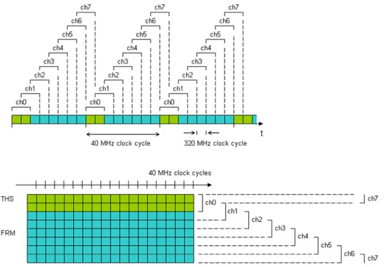
To overcome these problems, the idea was that of reserving to trigger sequences a dedicated time-division channel, inside the DAT serial stream, that is free from other data transmission so that triggers can be encoded as bit sequences in a way that allows to satisfy the requirements about latency and error robustness. This reserved channel is obtained through time division multiplexing: as said before, considering a transmission speed of 160, 320 or 640 Mbit/s, 4, 8 or 16 bits are transmitted in the DAT line in each 40 MHz clock cycle. This way the line can be regarded as a 40 MHz parallel link and conveniently split into two logical channels: the THS channel, so called because it is reserved, as will be explained later, to the transmission of Triggers, frame Headers and Synchronization patterns, and the FRM channel that carries data frames.
The next step is to decide the number of bits that are reserved to the THS channel (here and in the following, “in each 40 MHz clock cycle” is understood) and, related to this, the length of the bit sequence that represents the trigger. To this end, the following considerations/constraints must be kept in mind:
- to minimize the bandwidth fraction that is subtracted to data transmission, it would be preferable to have a “narrow” THS channel. i.e. the number of bits for the THS channel should be as small as possible;
- the trigger sequence must last not more than three 40 MHz clock cycle, since this is the minimum interval between two consecutive trigger commands; this condition was chosen considering the CMS requirements, that appears to be the most restrictive regarding this aspect [14];
- even in case of (single) bit-flip, the trigger sequence must be always recognized by the receiver with correct timing: that is, if a corrupted trigger sequence arrives to the receiver at the 40 MHz clock cycle number i, the receiver must not detect a trigger sequence at the 40 MHz clock cycle number i−1 or i+1.
To satisfy at best the first requirement, one could think to assign just one bit to the THS channel: however this would imply, for the second constraint, that the sequence representing the trigger is just 3 bits long. But this is not sufficient to fulfill the last requirement: supposing for example that all zeroes are transmitted onto the THS channel in absence of triggers, and that the trigger sequence is 111, if ...0000110000... is received because of a bit-flip then it is not possible to say with certainty where is the beginning of the sequence (it could be ...0000110000... or ...0000110000... depending on whether the bit preceding the two 1s or the bit following them is considered to be corrupted); the same problem arise with all the other possible choices of the 3-bit sequence encoding the trigger. Therefore, it was decided to assign 2 bits to the THS channel, and consequently to encode the trigger as a 6-bit sequence: this allows to fulfill all the previously
mentioned requisites, as will be shown later on. Consequently, the FRM channel has 2, 6 or 14 bits in each 40 MHz clock cycle for a transmission speed of 160, 320 or 640 Mbit/s, respectively: this is schematically illustrated in Fig. 2.1 for the cases 160 and 320 Mbit/s:
Fig. 2.1 – The division of the serial DAT stream in the THS channel and the FRM channel, in the cases of transmission
speed equal to 160 and 320 Mbit/s.
The FRM channel is used instead for the transmission of frames, that carry general, low priority user data and whose beginning is marked by a header, that is a special sequence of bits. As will be explained in section 2.2.3, the 6-bit encoding used for trigger allows to represent up to three different patterns (in addition to the “no operation” sequence, i.e. the one that is transmitted when the channel is idle) with the desired properties of robustness to bit-flip: therefore, beside the trigger, also the frame header is encoded as one of these patterns and transmitted in the THS channel as well, thus reducing the framing overhead in the FRM channel; the third available sequence can be used to encode “sync” patterns, i.e. sequences that are transmitted to maintain synchronization of the receiver on the THS channel of the received stream. The THS channel indeed gets its name from the names of the patterns that are transmitted on it: Trigger, Header and Sync.
The operation of the THS channel, the synchronization mechanism and the structure of FF-LYNX frames are described in more detail in the following sections.
2.2 The THS channel
The THS channel is therefore a 2-bit wide sub-stream in the DAT serial bit stream, reserved for the transmission of trigger and header 6-bit sequences, that will be called in the following TRG and HDR; this is the basic function of the THS channel although, as will be explained in the following, in a preliminary version of the protocol also a third sequence, denoted as SYN, was foreseen to be transmitted into the THS channel, and used as a synchronization pattern for the receiver.
Two main issues arise about the function of the THS channel: TRG and HDR scheduling, i.e. the timing organization of the transmission of these two sequences so that the TRG has always a fixed latency between transmission and reception, and synchronization of the receiver, that is the mechanism by which the receiver interface is able to distinguish, in each 40 MHz clock cycle, the 2 bits that belong to the THS channel from the bits of the FRM channel. These two issues are treated