Chapter 6
NEW CONCEPT DIESEL HCCI COMBUSTION –
A PRELIMINARY STUDY
6.1. INTRODUCTION
The purpose of this part research is an innovative concept to control HCCI combustion behavior in diesel-fuelled engines apart from exhaust gas presence, the function of which is limited to NOx emission control, and to avoid the high pressure gradients typical of present diesel HCCI solutions.
The concept consists in forming a pre-compressed homogenous charge outside the cylinder and in gradually admitting the charge into the cylinder during the engine combustion phase, so that combustion control is delegated to the charge transfer process.
In the conceived solutions the charge is formed during the air transfer to the cylinder from a constant-pressure tank. Thus combustion takes place at virtually constant pressure during the first part of the downward stroke of the piston. In this way, diesel HCCI combustion can be attained also with high mean effective pressures. Combustion behavior can be well controllable and soot emissions extremely contained in every operating condition. NOx emissions can be about the same of present diesel HCCI solutions at low mean effective pressures, since the charge can be diluted by exhaust gases and, at high mean effective pressures, can still be smaller than in conventional C.I. engines, thanks to charge homogeneity.
In this third part of the research activity a first analysis is addressed to the feasibility of the concept and subsequently two different realizations are considered. Both these proposed solutions are then compared with a diesel combustion case in terms of pressure, heat release rate, temperature and emissions production. Finally, an optimization for the mixture formation process has been performed.
6.2. CONCEPT
VALIDATION
A first CFD analysis has been done only to test the validity of the concept, regardless of which effective solution will be adopted. A single cylinder filled with a perfectly stirred mixture of air and diesel fuel through a transfer duct has been considered in the simulation. The simulation starts from TDC with initial conditions reported in Table 6.1. Transfer and combustion phase occur at the beginning of the downward piston stroke. Cylinder pressure is kept constant thanks to proper
Table 6.1. Simulation settings for the concept validation. Displacement (cm3) 1932
Bore (mm) 135
Stroke (mm) 135
Engine speed (rev/min) 2400 Global equivalence ratio
(Full load /1/3 of Max. load) 0.588 / 0.196
Initial P (MPa) 6.8
Initial T (K) 1150
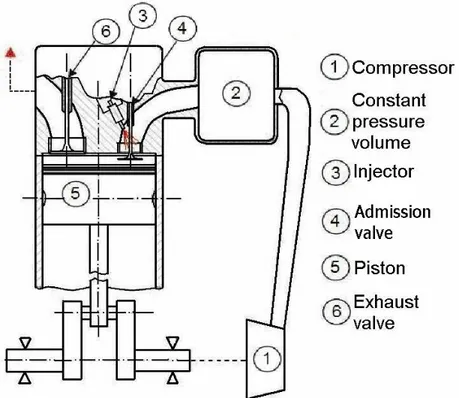
transfer flow rate. This condition has been fulfilled in the simulation by imposing constant pressure conditions on the inlet surface during the transfer. In Fig. 6.1 a schematic of the problem is reported. In Fig. 6.2 the computational grid of about 20000 cells at TDC is reported. Despite the problem is axial symmetric half of the engine geometry was considered for a better visualization of combustion.
The simulations have been performed using AVL FIRE release 8.5 [15]. The turbulence model based on the RANS method is the two-equation K-ε model, very common in computational fluid dynamics, which takes into account the effects of turbulence in the mean flow. Ignition and combustion were simulated using the AVL DIESEL [94] autoignition model coupled with the Eddy Breakup Model.
Only the combustion phase has been examined, starting from TDC while the charge begins to enter the cylinder. Pressure and temperature initial conditions have been calculated by a zero-dimensional code.
Figure 6.1. Schematic of the proposed concept.
Figure 6.2. Computational grid with around 20000 cells at TDC. Inlet
Head
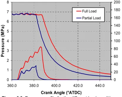
Two different load conditions (full load and 30% of maximum load) have been considered. In Fig. 6.3 pressure profile and heat release rate are given for full and partial load conditions. These plots show that combustion occurs with almost constant pressure (oscillations are in the range of a couple of bar). The heat is released in a gradual way as well, as it was expected. The obtaining of almost constant pressure combustion allows using high engine compression ratio and consequent high initial pressure and temperature conditions. This satisfies the basic idea of diesel cycle of obtaining the highest efficiency for a given maximum
0 1 2 3 4 5 6 7 8 360.0 380.0 400.0 420.0 440.0
Crank Angle (°ATDC)
P ressu re ( M P a ) 0 20 40 60 80 100 120 140 160 180 200 Full Load Partial Load H R R (J /d eg )
Figure 6.3. Pressure profile for the different load conditions.
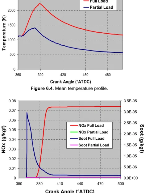
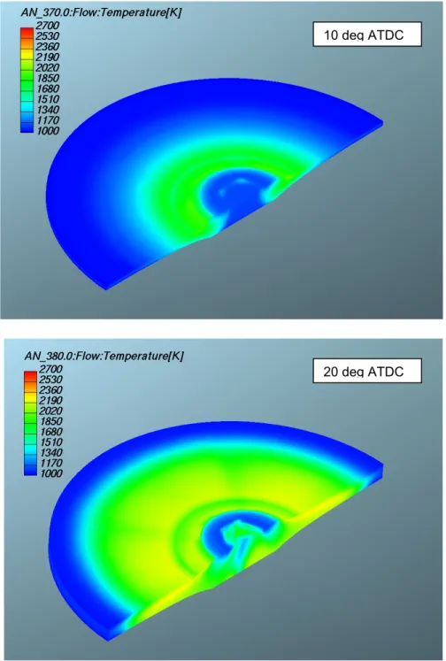
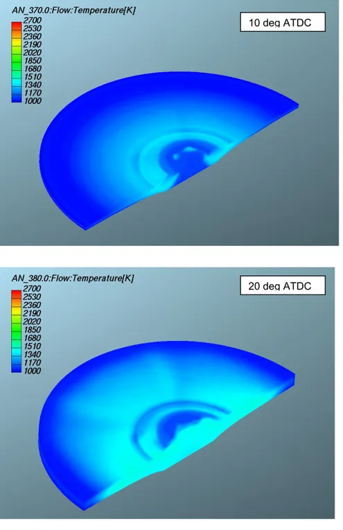
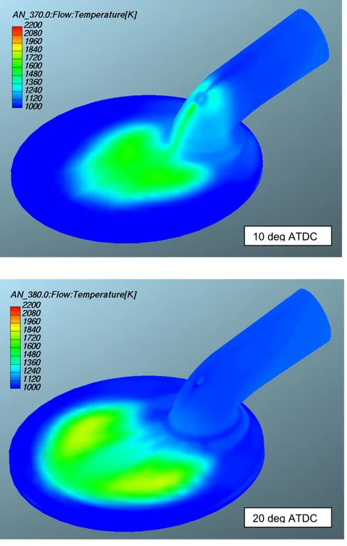
admissible pressure, as well as noiseless and smooth engine operation. As in the diesel ideal cycle, the crank angles over which cylinder pressure is kept at its maximum (constant) value depend on the engine load. In Fig. 6.4 mean temperature distributions are given for full and partial load condition. In Fig. 6.5 NOx and soot emission results are given. It can be seen that they are reasonably low. In Figs. 6.6 and 6.7 temperature distributions are reported for the two considered load conditions at two fixed crank angles. It can be observed that local temperatures are fairly low, thanks to homogeneous charge burning in the cylinder.
0 500 1000 1500 2000 2500 360 390 420 450 480
Crank Angle (°ATDC)
T em per a tur e (K ) Full Load Partial Load
Figure 6.4. Mean temperature profile.
0 0.01 0.02 0.03 0.04 0.05 0.06 0.07 0.08 350 380 410 440 470 500
Crank Angle (°ATDC)
NO x (g /k g f) 0.0E+00 5.0E-06 1.0E-05 1.5E-05 2.0E-05 2.5E-05 3.0E-05 3.5E-05 S oot ( g /k gf )
NOx Full Load NOx Partial Load Soot Full Load Soot Partial Load
Figure 6.5. NOx and soot results for concept validation simulation.
Figure 6.6. Temperature distribution in full load condition. 10 deg ATDC
20 deg ATDC
Figure 6.7. Temperature distribution in partial load condition.
10 deg ATDC
20 deg ATDC
6.3. PROPOSED
SOLUTIONS
As previously mentioned, in this preliminary study two different solutions are proposed to allow the gradual admission to the cylinder of a pre-compressed homogenous charge during combustion. The first one involves the two-stroke cycle, the other the four-stroke one, as the sketches reported on Figs. 6.8 and 6.9 show.
The first solution (Fig. 6.8) is based on split cycle concept, with intake and compression phases performed outside the cylinder. Compression is realized by an external volumetric compressor which drives the air into a tank sized to keep pressure nearly constant and performs the same compression work accomplished by engine piston in a four stroke engine. The compressor displacement, in a first approximation, is the same of the cylinder. The high-temperature compressed air is transferred to the cylinder through an inlet valve during the engine combustion phase. Contemporary with the air transfer, fuel is injected into the transfer duct, evaporates and mixes with air, bringing about the conditions for homogeneous combustion. Compressor work recovery takes place during the downward piston stroke, due to engine work produced by the transferred air.
Figure 6.8. Schematic of the two stroke solution.
Figure 6.9. Schematic of the four stroke solution.
In the second solution, related to four-stroke cycle (Fig. 6.9), the air is directly compressed by the piston during the compression stroke. The maximum pressure is reached before the piston arrives to TDC; then compressed air begins entering a secondary chamber which is in constant communication with the cylinder. The volume of this secondary chamber, theoretically starting from zero, varies keeping pressure constant during the last part of the compression stroke and during combustion, thanks to a moving wall over which a constant pressure acts (the volume must be large enough to minimize pressure oscillations due to wall movement; a small compressor gives the pressure and compensates air leakages). When the piston begins its down-stroke, the air is transferred back into the cylinder while fuel is injected, evaporates and mixes with air, bringing about the conditions for homogeneous combustion.
Both the solutions allow getting constant combustion pressure satisfying the basic idea of diesel cycle. This allows obtaining the highest efficiency for a given maximum admissible pressure, as well as noiseless and smooth engine operation, because pressure is gradually reached during the compression stroke. Also mechanical efficiency is improved due both to the absence of pressure peaks and to the consequent reduction of reciprocating masses.
6.4. PROPOSED SOLUTIONS CFD ANALYSIS
CFD simulations have been performed to study both the two-stroke and the four-stroke solutions. Results regarding pressure, heat release rate and temperature distribution are shown. Being the injection process accounted in this
part of the study, the Discrete Droplet Model (DDM) [95] has been used together with the Taylor Analogy Breakup (TAB) model and the Dukowicz evaporation model [96] for the spray behavior prediction. Emissions model as Zeldovich and Kennedy-Hiroyasu-Magnussen have been used to predict NOx and soot production respectively. Ignition and combustion models are the same used in the concept validation part.
Two different load conditions have been considered taking injection and mixing processes into account. Differently from the previous case, boundary and initial conditions have been calculated using the AVL BOOST release 5.0 [97] one-dimensional code (models are reported in APPENDEX C).
In Figs. 6.10 and 6.11 the grids of the two solutions are shown. Actually, while in the figures the whole cylinder mesh is represented, only one half of it has been used in the simulation for computational time saving, since both the solutions are symmetric. Subsequently, during post-processing, the results have been extended to the whole domain for a better visualization. Both the grids used in the simulations are constituted by around 40000 cells at TDC. In both the two-stroke and the four-stroke solutions of Figs. 6.8 and 6.9 pressure is supposed to be kept nearly constant in the transfer duct thanks to the constant pressure tank and to the moving wall respectively. Therefore the air transfer is influenced only by the pressure into the combustion chamber. Because of this, the computational domain for both the solutions considers only the combustion chamber and the transfer duct. An inlet surface has been positioned at the boundary of the duct with a static pressure of 6.8 MPa, obtained from the one-dimensional simulation.
Figure 6.10. Computational grids of the two-stroke solution.
Figure 6.11. Computational grids of the four-stroke solution.
Only the air transfer and the combustion phase have been considered in the simulations, therefore in the four-stroke domain the valves have not been represented. In the two-stroke solution only the inlet valve has been considered. The fuel is injected by means of an 8-hole diesel injector located in the transfer duct. The injector is located on the transfer duct symmetry plane and in Figs. 6.10 and 6.11 the arrows point out the injection direction.
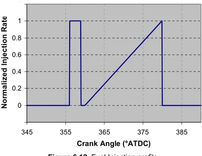
-0.2 0 0.2 0.4 0.6 0.8 1 1.2 345 355 365 375 385
Crank Angle (°ATDC)
N o rm a liz e d Inje c ti on R a te
Figure 6.12. Fuel Injection profile.
Table 6.2. Simulation settings for the proposed solutions. Displacement (cm3) 1932 Bore (mm) 135 Stroke (mm) 135 RPM (rev/min) 2400 Inlet P (MPa) 6.8
Injector Type 8 nozzle equally-spaced Multihole injector
Injector pressure (MPa) 150
Included angle (deg) 75
Global equivalence ratio
(Full load /1/3 of Max. load) 0.588 / 0.196 Full Load Main Injection duration (DOI) (ca) 20
Main Injection timing (SOI) (ca) 360
In Fig. 6.12 the fuel injection rate is given. A pre-injection, opportunely phased, has been adopted before TDC to reduce the ignition delay (ID) of the main combustion and, therefore, to obtain a smoother heat release. Apart from pressure waves, the air mass enters the cylinder according to the piston velocity. For the main injection rate, a triangular shape has been assumed that approximates piston velocity behavior soon after TDC. This is acceptable, since the main injection covers only a very short part of the piston stroke. The simulation settings common to the two solutions have been reported in Table 6.2.
In Figs. from 6.13 to 6.16 pressure, heat release rate and mean temperature profiles have been given for both the two-stroke and the four-stroke solutions in the different load conditions.
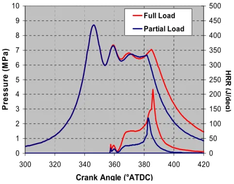
Likewise in the concept validation results, pressure remains almost constant during the combustion phase and the heat is released in a gradual way as well. However, in respect of concept validation results, bigger oscillations are present at the beginning of air transfer due to pressure losses in the transfer duct, not considered before. Comparing the HRR profiles it appears that the Two-Stroke combustion is longer than the Four Stroke one. This is probably due to the fact that, for simplicity, the injection profile is the same adopted in the Four Stroke case and does not match with the real air inflow to the cylinder.
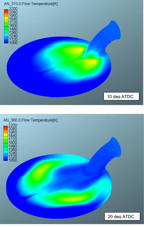
Temperature distributions for the two solutions in partial load condition are reported in Figs. 6.17 and 6.18 at two different crank angles. These figures show that low combustion temperatures are kept everywhere in the chamber. However, compared with the concept validation results, temperatures are much less homogeneous, proving that injection and mixing processes are not (yet) optimized.
0 1 2 3 4 5 6 7 8 9 10 300 320 340 360 380 400 420
Crank Angle (°ATDC)
P resur e ( M P a ) 0 50 100 150 200 250 300 350 400 450 500 Full Load Partial Load H R R (J /d eg )
Figure 6.13. Pressure and HRR for the two stroke solution.
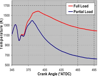
500 700 900 1100 1300 1500 1700 345 375 405 435 465 495
Crank Angle (°ATDC)
Te m p e rat ur e ( K ) Full Load Partial Load
Figure 6.14. Mean temperature profile for the two stroke solution.
0 1 2 3 4 5 6 7 8 9 10 300 320 340 360 380 400 420
Crank Angle (°ATDC)
P
ress
ur
e
(M
P
a
)
0 50 100 150 200 250 300 350 400 450 500 Full Load Partial Load H R R (J /d eg )Figure 6.15. Pressure and HRR for the four stroke solution.
500 700 900 1100 1300 1500 1700 345 375 405 435 465 495
Crank Angle (°ATDC)
Te
m
p
er
at
ur
e (
K
)
Full Load
Partial Load
Figure 6.16. Mean temperature profile for the four stroke solution.
Figure 6.17. Temperature distribution for the two-stroke solution in partial load condition .
10 deg ATDC
20 deg ATDC
Figure 6.18. Temperature distribution for the four-stroke solution in partial load condition.
10 deg ATDC
20 deg ATDC
6.5. CONVENTIONAL DIESEL ENGINE APPLICATION
A Heavy Duty Diesel engine has been taken as reference for comparison with the new concept HCCI combustion. Simulations have been performed from IVC to EVO at the same loads of the previous cases. Initial conditions have been obtained by a zero-dimensional code.
Piston geometry and computational grid used for this simulation are shown in Fig. 6.19. A 45˚ sector mesh has been used in this study, considering that the diesel injector employed has eight equally-spaced nozzle holes. All major geometric dimensions of the experimental combustion chamber, including bore, stroke, bowl volume and squish height have been replicated in the computational grid. The computational grid has about 20000 cells at TDC. In Table 6.3 and 6.4 engine and injection system features are summarized.
Figure 6.19. Computational grid of a HD Engine at TDC. Table 6.3. HD Engine specifications.
Engine type Heavy Duty Diesel Engine (HD)
Engine speed
(rev/min) 2400
Displacement (cm3) 1932
Compression ratio 20.3 Valve timing
IVC = 215 deg ATDC EVO = 500 deg ATDC
Bore (mm) 135
Stroke (mm) 135
IVC Pressure (MPa) IVC Temperature (K)
0.109 360
Table 6.4. Injection system specifications. Injector Type Multihole injector with 8 equally-spaced nozzles Injector pressure (MPa) 150
Included angle (deg) 75 Global equivalence ratio
(Full load /1/3 of Max. load) 0.588 / 0.196
SOI (ca) 310
Full load DOI (ca) 21
In Fig. 6.20 and 6.21 pressure, heat release rate and mean temperature profiles are shown. From mean temperature profiles it appears that diesel combustion leads to higher temperatures than the two proposed HCCI solutions for both full and partial load. This was expected due to the faster diesel combustion.
0 2 4 6 8 10 12 14 315 335 355 375 395
Crank Angle (°ATDC)
P res su re ( MPa ) 0 50 100 150 200 250 300 350 400 450 500
Diesel Full Load Diesel Partial Load
H R R (J /d eg )
Figure 6.20. Pressure and HRR of the HD Diesel engine.
0 500 1000 1500 2000 2500 300 330 360 390 420 450 480
Crank Angle (°ATDC)
Te m p er a tur e ( K ) Full Load Partial Load
Figure 6.21. Mean temperature profile for the HD Diesel engine.
From mean temperature profiles it appears that diesel combustion leads to higher temperatures than the two proposed HCCI solutions for both full and partial load. This was expected due to the faster diesel combustion.
6.6. EMISSION
RESULTS
Comparison in emission production is shown in Figs. from 6.22 to 6.25. NOx and Soot production for both full and partial load conditions is reported for the two proposed HCCI solutions and for the HD diesel case as well.
The results show that the Two Stroke solution produces more soot than the already shown concept validation case, named as ideal solution, and than the diesel case as well. This points out that the air-fuel mixing is probably not optimized. This is also confirmed from the fact that in the Four Stroke solution, not being present any valve in the transfer duct, the charge can mix better and the soot production is less, as it is also confirmed from Fig. 6.26 where equivalence ratio maps are reported for the full load conditions. Then, a contribute to the Two Stroke soot production could be given also by its long combustion tail ending in advanced expansion stroke, therefore avoiding the oxidation of soot. Regarding NOx emissions, the diesel case gives the higher production both for the full and partial load conditions and this, as well known, is related to high local combustion temperatures, while good results come from concept validation simulation. Good results come also from Four Stroke case simulation, even if, as expected, worse than for concept validation simulation. At full load the best results (even better than for concept validation) come from the Two Stroke solution. This apparently odd outcome should be due to delayed combustion of part of the fuel. This is proved by
the heat release curve and, on the other hand, causes the high soot emission seen before.
Figure 6.22. Soot emissions in full load condition.
Figure 6.23. NOx emissions in full load condition.
Figure 6.24. Soot emissions in partial load condition.
Figure 6.25. NOx emissions in partial load condition.
20 deg ATDC
20 deg ATDC
Figure 6.26. Equivalence ratio distributions for Ideal, two and four stroke solutions in full load condition.
20 deg ATDC
6.7. INJECTION PROCESS OPTIMIZATION
From the emissions analysis discussed in the previous paragraph it emerges that, especially at high loads, the homogeneous charge formation process needs to be improved. In both the proposed solutions fuel-rich regions are present into the combustion chamber at the beginning of the combustion process with consequent rapid heat release and really high emission levels.
For both the proposed solutions an injection optimization process is performed in order to reduce the in-cylinder charge in-homogeneities. The optimization process regards the full load operation, being this condition critical.
6.7.1. OPERATING CONDITIONS
For both the proposed solutions several multi-hole injectors, different for holes number and included spray angle, were tested in several chosen position with several spray orientation.
Multi-hole injectors with 8 and 16 holes equally spaced, with included spray cone of 75° and 90° have been applied for this optimization process. In Fig. 6.27 a schematic representing the two included spray angle adopted is reported. In Figs. 6.28 and 6.29 the various injection positions and orientations adopted for both the proposed solutions are reported. Positioning “A” represents the baseline case considered in the previous results. Positioning “C” for the two stroke solution should be considered only from a theoretical point of view, being impossible to place the injector inside the duct with that orientation.
Figure 6.27. Included spray angle used in the optimization process.
Figure 6.28. Injector positioning and orientation for the two stroke solution.
C
D
B
A
Figure 6.29. Injector positioning and orientation for the four stroke solution.
C
D
B
A
6.7.2. EMISSION AND HRR RESULTS
NOx and soot emissions for both the proposed solutions are reported in Figs. from 6.30 to 6.33 for all the considered positions and injectors.
Figure 6.30. Soot production for the two stroke solution.
Figure 6.31. NOx production for the two stroke solution.
Figure 6.32. Soot production for the four stroke solution.
Figure 6.33. NOx production for the four stroke solution.
For the two stroke solution the best results are obtained with injector positioned before the valve (“C” and “D”) since the fuel impingement on the valve can be minimized. NOx emissions indicate an opposite behavior since , with injector in positions “C” and “D”, combustion efficiency increases consistently. With
16 holes injector in position “D” low soot and acceptable NOx emissions can be obtained.
For the four stroke solution from the plots immediately emerges that 16 holes injector placed in position “A” gives the best results for both the included spray angle, with low soot and slightly higher NOx compared with the 8 holes case. This is due to the slightly increased combustion efficiency.
The best injection configurations have been compared with the baseline case in terms of HRR, in order to evaluate the presence of effective improvements on combustion process. In Fig. 6.34 and 6.35 HRR profiles have been reported for the chosen cases.
Figure 6.34. HRR profiles for the two stroke solution.
For the two stroke solution a shorter combustion duration emerges from the HRR rate profiles. Further on, higher maximum values ca be reached, thanks to a more efficient combustion leading to low soot emission as well. The HRR profile results similar for all the tested injection configurations, however, the 16 holes injector with 75° included spray angle leads to faster combustion.
For the four stroke solution it appears that the fuel pre-injection burns around TDC, when main combustion begins. The HRR curve show that the main combustion is initially progressive then, the increase in in-cylinder pressure obstacles the fresh charge entering the admission duct. The fuel accumulates in the duct then, when it finally enters the cylinder and starts burning, it burns very quickly causing a peak in HRR around 25° ATDC. This indicates that, in a next step of this research, the injection law needs to be optimized.
Figure 6.35. HRR profiles for the four stroke solution.
6.8. SUMMARY AND CONCLUSIONS
The study supports that present limitations of HCCI diesel combustion can be overcome thanks to innovative ideas. An innovative concept has been proposed together with preliminary CFD study. The concept consists in forming a pre-compressed homogenous charge outside the cylinder and in gradually admitting the charge into the cylinder during the engine combustion phase, so that combustion control is delegated to the charge transfer process and nearly constant-pressure combustion can be obtained.
Two possible realizations have been proposed and compared with a diesel combustion case. Results in terms of pressure, heat release rate, emissions and temperature distribution have been provided. However, while combustion gradually spreads in the whole chamber as expected, soot emissions are not yet satisfactory and should be reduced by optimizing injection strategy and turbulence effects.
An injection process optimization has been performed on both the proposed solutions. Different injectors have been used in several positions of the admission duct. Results shown that the mixture formation process represents a fundamental process for the obtaining of a gradual combustion.
This encourages further research, including experimental activity.