7. EBRP
(End-to-end Bandwidth Reservation Protocol)
The MAC protocol is based on Time Division Multiple Access (TDMA) and communications occur on a time frame basis. Each frame consists of a control sub-frame and a data sub-frame. Control sub-frames are partitioned into slots of fixed duration, called control slots, up to a maximum of 16 per frame. Likewise, data sub-frames consist of a fixed number of mini-slots, up to 256. The control slots are accessed by means of a distributed procedure, i.e. the mesh election procedure, which provides nodes with a collision-free access to the control sub-frame.
Figure 7.1 – Example of frame data structure, with three channels.
The control slots are used by the nodes to transmit control messages which can be employed for several purposes. EBRP exploit the control messages to solve the problem of providing traffic flows with strict real-time requirements. EBRP add of some information elements to the MAC control messages.
The field priority in CID (header MAC) recognizes the real time flow packets setting it with a certain priority value:
• 00: none EBRP message. • 01: PATH message. • 10: RSV message. • 11: CNF message.
7.1 EBRP
Message
The messages that are used to establish traffic flows are conveyed as Information Elements (IEs) of Mesh Distributed Scheduling (MSH-DSCH) MAC control messages. The MSH-DSCH format has been modified so as to be still compliant with the IEEE 802.16 standard, because EBRP uses the fields that are reserved for future use. Due to control message size limitations, at most one EBRP IE is encapsulated into each MAC control message.
7.1.1 Path Message (PATH)
PATH message is forwarded from the node that requests the admission of a new traffic flow to its destination.
Path message contains: • Sender Node ID. • Receiver Node ID. • Flow identifier.
• List of intermediate Node IDs. • Packet size (in bytes).
• Packet period (in seconds).
In an IEEE 802.16 mesh network each node is uniquely identified by means of a 16-bit node ID, which is assigned by the BS when a network enters the network. The node ID is used instead of the IPv4 or IPv6 address to identify nodes because it is shorter.
I assume that a Shortest Path First (SPF) policy is used by nodes to forward the PATH message.
7.1.2 Reservation Message (RSV)
RSV message proceeds backwards from the destination node to the node that originated the request. Reservation message contains:
• Sender Node ID. • Receiver Node ID. • Flow identifier.
• List of intermediate Node IDs. • Packet size (in bytes).
• Packet period (in seconds). • Start frame number. • Minislots allocated. • Channel number.
7.1.3 Confirmation Message (CNF) CNF message contains:
• Sender Node ID. • Receiver Node ID. • Flow ID.
7.2 EBRP
Benefits
• The time required for the resource reservation process is expected to be dramatically decreased because reservation messages are encapsulated into MAC control messages.
• Optimized and efficient fine-grained resource allocation strategies can be envisaged exploiting information present at the MAC layer.
• The addition of information elements to the control messages does not affect the semantics of the latter. In other words, any non-EBRP node will simply ignore the additional information present in the control messages, thus guaranteeing a seamless integration of our solution into the IEEE 802.16 MAC.
7.3
Soft State Behaviour
Soft state is better than hard state because doesn’t use control slot or bandwidth for keep alive or remove connection.
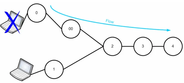
7.3.1 Moving of the Terminal First scenario
Figure 7.3 – Terminal moving 1.
• The terminal moves from node 0 to node 1.
• The flow has a flow ID so node 2 hears the flow arriving from node 1 and not from node 0. • Node 2 reserves minislot towards node 1 but doesn’t touch reservation towards node 3. • Node 0 deletes the state because packets don’t arrive from the terminal.
Flow timeout (TF) in this case is enough large.
Second scenario
• The terminal moves from node 0 to node 1.
• The flow has a flow ID so node 2 hears the flow arriving from node 1 and not from node 00. • Node 2 reserves minislots towards node 1 but doesn’t touch reservation towards node 3. • Node 0 deletes the state because TF expires.
• Node 00 deletes the state because TF expires. 7.3.2 Breaking of the Link or Node
First scenario
Figure 7.5 – Breaking of the Link or Node 1.
• TF expires in node 2 and node 3, these nodes discard the state.
• Node 0 knows that the link is broken, finds a new route and remakes signaling. Second scenario
• Node 00 is the source, between node 00 and node 0 there is not change.
• Node 0 knows that the link is broken, finds a new route and remakes signaling. • TF expires in node 2 and node 3, these nodes discard the state.
Third scenario
Figure 7.7 – Breaking of the Link or Node 3.
• Node 00 is the source, between node 00 and node 0 there is not change.
• Node 0 knows that the link is broken, finds a new route and remakes signaling. • TF expires in node 2, this node discards the state.