POLITECNICO DI MILANO
Master degree in Computer Science and Engineering Dipartimento di Elettronica e Informazione
A Hybrid Fault Injection Framework for
Image Processing Applications in FPGA
Supervisor: Antonio Rosario Miele Co-supervisor: Luca Maria Cassano
Author: Andrea Mazzeo, matr. 895579
Abstract
Nowadays there is a growing interest in using Image Processing applications in safety-/mission-critical systems, also to support control decisions. Rele-vant examples span from the large employment of such applications as pay-load in satellites and other spacecraft aimed at elaborating images on-board before transmitting to the ground station, to the recent adoption of image processing and machine learning algorithms to perform obstacle and pedes-trian detection in autonomous driving systems. These classes of applications are inherently resilient to a certain degree of noise/error because i) they pro-cess data acquired from sensors, ii) the outputs are probabilistic estimates, or iii) limited deviations from the exact output might be acceptable. This peculiarity opens new challenges and opportunities when considering the stringent reliability constraints that typically characterize mission-/safety-critical application scenarios. More precisely, the impact of the faults on the quality and usability of the final result highly depends on where/when the upset occurs during the execution of the payload application. As an example, a fault may cause the final image to be severely damaged and thus unusable, whereas in other cases it could be still used either by a human user, or other classification applications. On the other hand, the assessment and enhancement of the reliability of such a kind of applications becomes much more complex and requires a more accurate analysis of the effect of the occurred faults. As a matter of fact, the classical fault injection campaigns applied on the final or prototype version of the system does not suffice in giving fast feedback to the design activities; at the opposite, it becomes relevant to perform an early reliability evaluation in the first phases of the design flow.
For this reason, the purpose of this thesis is to define a hybrid cross-layer fault injection framework for complex image processing applications based on a pipeline of filters. The framework is capable at performing reliability analysis at various levels of abstraction; in particular, as classically per-formed, at a lower level in the system implementation and at a higher level
in the algorithmic description of the application, implemented in software. The final goal of the framework is to support the designer in understand-ing if an image processunderstand-ing application is sufficiently resilient against faults, or it needs to be hardened; in the latter case, whether it suffices to focus only on some parts/step of the application pipeline, to keep overheads to a minimum (to save power, time, area) or it is mandatory to harden the en-tire system. The considered working scenario for designing the hybrid fault injection framework focuses on image applications implemented on recon-figurable devices, in particular Field Programmable Gate Arrays (FPGAs), and on Single Event Upsets (SEUs), that is the most frequent type of fault occurring in such a kind of device due to the effects of radiations influencing the circuits’ status.
The first contribution of the thesis is the design of the hybrid fault in-jection framework for the considered scenario, i.e. image processing applica-tions implemented onto FPGA. The framework integrates both an architecture-level FPGA fault injector, emulating SEUs in the programmable configura-tion, and an application-level error simulator, based on saboteurs corrupting the output of a single step of the application pipeline. In order to focus the reliability analysis on an application step at the time, the framework allows to run the entire application in software, at application-level, thus abstract-ing from the underlyabstract-ing architectural details and to focus the accurate fault injection on the step under test. The key feature is the application-level error simulation which allows replacing the system implementation, and so save a considerable amount of time both in design and experiments execution stages.
In order to enable the switch from the architecture-level fault injection to the higher application-level error simulation requires an accurate defini-tion of the effects of the faults injected in the programmable logic of the FPGA device at the outputs of the single stages of the application pipeline. Therefore, the second contribution of the thesis is a method to define er-ror models; such models are implemented in terms of patterns describing the corruptions caused by a fault in the 2D grid of pixels of the elaborated image (e.g. in terms of colour changes or black bands horizontal spanning the entire image). This abstraction will be integrated into the higher-level simulation environment that makes possible to replace the classical fault in-jection campaign with the smarter error simulation approach, that neglects all the architectural dependencies.
We employed the proposed framework in a case study considering a com-mon class of image processing algorithms widely used as steps in applica-tion pipelines, that are the convoluapplica-tion filters. We performed an extensive
architecture-level fault injection campaign on hardware implementation of various types of convolution filters devoted to the analysis of the effects of fault injected in the FPGA on the filters’ outputs. Based on an in-depth analysis of the results we defined a set of fault models, most of them are general for the overall class of convolution filters while some other one spe-cific for the kernel. Such fault models have been finally validated with a second fault injection campaign, where the same types of error and related occurrence probability has been found. Indeed, such a modelling activity is performed only a single time on the specific application’s building blocks. Once, error models are integrated into the error simulator, the designer can perform reliability analysis of any type of applications integrating such fil-ters without any necessity to implement the hardware modules and use the FPGA fault injector. Furthermore, shifting to error simulation, the high time-consuming fault injection campaign can be replaced by software emu-lation without losing any functionality.
Sommario
Al giorno d’oggi c’`e un crescente interesse nell’utilizzo di applicazioni per l’elaborazione digitale delle immagini in sistemi critici, anche impiegati come supporto nei processi decisionali. Esempi rilevanti vanno dall’impiego di tali applicazioni di payload in satelliti dedicati all’elaborazione delle im-magini prima che esse vengano trasmesse alla stazione base e ai recenti usi di algoritmi di machine learning e applicazioni di elaborazione digitale di immagini per il riconoscimento automatico di ostacoli o pedoni in sis-temi che supportano la guida autonoma. Questa tipologia di applicazioni ha un’intrinseca tolleranza ad un determinato grado di inesattezza poich`e i) processano dati acquisiti tramite sensori, ii) i risultati finali sono sti-mati in modo probabilistico, e iii) minime deviazioni dal risultato esatto possono essere tollerate. Questa caratteristica apre nuove sfide e opportu-nit´a quando vengono considerati vincoli di affidabilit´a altamente restrittivi che tipicamente caratterizzano le applicazioni impiegate in ambiti critici. Pi´u precisamente, l’impatto dei guasti sulla qualit´a e l’usabilit´a del risul-tato finale dipende profondamente da dove/quando il guasto avviene du-rante l’esecuzione delle applicazioni di payload. Per esempio, un guasto pu´o compromettere fortemente l’immagine finale e quindi renderla inutilizzabile, mentre in altri casi l’immagine, seppur corrotta, potr´a essere usata da utenti o da altre applicazioni a valle. D’altra parte, la valutazione e il migliora-mento dell’affidabilit´a di tali applicazioni diventano molto pi´u complesse e ci´o richiede un’analisi dell’effetto causato dal guasto molto pi´u dettagliata. Difatti, la classica campagna di iniezione guasti eseguita sulla versione finale o il prototipo del sistema non fornisce un riscontro immediato alle attivit´a di progettazione; al contrario, diviene importante eseguire un’analisi di af-fidabilit´a anticipata alle prime fasi.
Per questo motivo, lo scopo della tesi `e di definire un framework di iniezione guasti ibrido su pi´u livelli per applicazioni di elaborazione delle immagini complesse basate su una pipeline di filtri. Il framework `e in grado di eseguire analisi di affidabilit´a con vari livelli di astrazione: in particolare,
come nell’approccio classico, a basso livello nell’implementazione del sistema e ad alto livello nella descrizione algoritmica dell’applicazione, implementata tramite software. L’obiettivo finale del framework `e fornire un supporto ai progettisti per comprendere se un’applicazione per l’elaborazione digi-tale delle immagini `e sufficientemente resistente contro i guasti, o necessit´a un irrobustimento; in questo caso, se `e sufficiente concentrarsi solo su una porzione della pipeline dell’applicazione, per ridurre al minimo i costi gener-ali (per risparmiare energia, tempo e consumo d’area) o se `e obbligatorio ir-robustire l’intera applicazione. Lo scenario considerato per la progettazione del framework di iniezione guasti ibrido si concentra su applicazioni imple-mentate su dispositivi riprogrammabili, in particolare Field Programmable Gate Array (FPGA), e sui Single Event Upset (SEU), che rappresentano la causa d’errore pi´u frequente in questo tipo di dispositivi, dovuti agli effetti indotti dalle radiazioni che influenzano gli stati dei circuiti.
Il primo contributo della tesi `e la progettazione del framework di iniezione guasti ibrido per lo scenario considerato, quindi applicazioni per l’elaborazione delle immagini implementate su FPGA. Il framework integra sia l’iniettore guasti a livello architetturale, emulando cos´ı i SEU nella configurazione pro-grammabile, sia a livello applicativo con la simulazione d’errore, basata sul sabotaggio dell’uscita del singolo filtro della pipeline. Il framework perme-tte di eseguire l’intera applicazione a livello funzionale tramite software, omettendo dettagli architetturali e concentrandosi in un’accurata analisi di affidabilit´a di un singolo componente alla volta. L’aspetto fondamen-tale `e la simulazione d’errore a livello applicativo che permette di sostituire l’implementazione del sistema, e quindi di risparmiare tempo, sia nella pro-gettazione sia nell’esecuzione degli esperimenti.
Il passaggio da iniezione guasti architetturale a simulazione d’errore ad alto livello richiede un’accurata definizione degli effetti sull’uscita del sin-golo filtro dovuti ai guasti iniettati nella logica programmabile delle FPGA. Perci´o, il secondo contributo della tesi `e una metodologia di definizione di modelli d’errore; Tali modelli sono implementati in termini di effetti che de-scrivono come il guasto corrompa la griglia 2D dell’immagine elaborata (per esempio variazioni di colore o bande nere che attraversano orizzontalmente l’immagine). Questa astrazione sar´a integrata nella simulazione d’errore che rende possibile la sostituzione della classica campagna di iniezione guasti con l’approccio emulativo, che trascura tutte le dipendenze architetturali.
Abbiamo impiegato il framework proposto in un caso di studio che con-sidera una classe di algoritmi di elaborazione delle immagini molto dif-fusa nelle pipeline di tali applicazioni, ossia i filtri convolutivi. Abbiamo eseguito un’estensiva campagna di iniezione guasti a livello architetturale
sull’implementazione fisica dei vari filtri convolutivi, orientata all’analisi degli effetti causati sull’immagine finale. Tramite un’approfondita analisi dei risultati, abbiamo definito un insieme di modelli d’errore, molti dei quali sono generali per la classe dei filtri convolutivi mentre altri lo sono per il sin-golo kernel. Tali modelli di guasto sono stati infine validati con una seconda campagna di iniezione guasti, la quale ha condotto ai medesimi modelli di errore, cos´ı come le relative probabilit´a di occorrenza. Tale attivit´a di mod-ellizzazione `e eseguita solo una volta per i vari componenti dell’applicazione. Una volta che i modelli di errore sono integrati con la fase di simulazione, il progettista pu´o eseguire analisi di affidabilit´a di qualsiasi tipo su appli-cazioni che integrino tali filtri, senza la necessit´a di alcuna implementazione fisica del sistema e l’uso di FPGA per condurre iniezioni. Spostandoci verso la simulazione d’errore, la campagna di iniezione guasti, che `e notoriamente molto dispendiosa dal punto di vista del tempo richiesto, pu´o essere sosti-tuita da una emulazione software, senza perdere alcuna funzionalit´a.
Ringraziamenti
The greatest enemy of knowledge is not ignorance, it is the illusion of knowledge. Stephen William Hawking
Finalmente dopo un lungo anno di lavoro il grande giorno `e arrivato e questi ringraziamenti sono la conclusione della mia tesi, ma soprattutto del mio percorso universitario. Vorrei spendere due parole per ringraziare tutte le persone che mi hanno aiutato in questi anni di studio e hanno contribuito al mio sviluppo, sia in quanto persona sia dal punto di vista professionale.
Prima di tutto devo ringraziare i professori Antonio Rosario Miele e Luca Maria Cassano per avermi dato la possibit´a di lavorare ad un progetto stimolante che rispetta a pieno i miei interessi, ma soprattutto per avermi supportato sin dall’inizio del lavoro offrendomi un ambiente lavorativo es-tremamente sereno e aiutato nei momenti di maggiore sconforto.
Ovviamente, un ringraziamento speciale va fatto alla mia famiglia, che ha reso possibile tutto questo e mi ha sempre supportato in questi cinque anni di studi. Senza di loro, che non hanno mai smesso di credere in me e dei loro preziosi consigli oggi sicuramente non sarei qui a celebrare questo grande traguardo.
Un altro grande ringraziamento va alla mia ragazza Claudia che mi ha sempre dato la forza di andare avanti dinnanzi alle mille difficolt´a e appog-giato senza mai tirarsi indietro, ma soprattutto ha sempre avuto la pazienza di sopportarmi durante i miei mille impegni e le mie paranoie.
Non posso che ringraziare anche tutti i miei compagni universitari Maffe, Dani, Fra, Ench, Edo, Ale, Sara e Alessia, conosciuti grazie al Politecnico, con i quali abbiamo sempre superato tutte le difficolt´a insieme.
Ma un ringraziamento speciale va fatto soprattutto ad una persona che purtroppo oggi non `e pi´u qui, il professor Giulio Vitale, che sin dal primo anno delle scuole superiori ha sempre creduto in me. `E anche grazie a lui che oggi posso festeggiare la mia laurea magistrale, perch´e `e lui che mi ha
convinto ad affrontare il percorso universitario e mi ha fatto appassionare a ci`o che da oggi sar´a la mia professione.
Ringrazio anche mio cugino Matteo e i miei amici Nico, Ilenia, Luca e tutti gli altri, con cui ho trascorso questi anni di studi e condiviso con loro le mie difficolt´a.
Con oggi termina la mia esperienza al Politecnico di Milano che anche se mi ha messo davanti a sfide che mai avrei pensato di poter superare, so che mi mancheranno i bei momenti passati qui dentro. Un ringraziamento va fatto a tutti i professori e le persone che ho incontrato in questi anni, che seppur in minima parte hanno comunque contribuito a farmi diventare ci`o che sono ora.
Grazie ancora! Andrea
Contents
List of Figures XVI
List of Tables XX
1 Introduction 1
1.1 Goals . . . 4
1.2 Thesis outline . . . 5
2 Background and Related Work 7 2.1 Image processing application . . . 7
2.2 Field Programmable Gate Array . . . 15
2.3 SEUs . . . 20
2.4 Related work . . . 22
2.4.1 FPGA based fault injector . . . 22
2.4.2 System level analysis and fault injection framework . . 24
3 Goals and Requirements 29 3.1 Working scenario . . . 29
3.2 Design constraints and framework needs . . . 31
3.2.1 Implementation complexity . . . 31
3.2.2 Methodology complexity . . . 32
3.3 Goal . . . 33
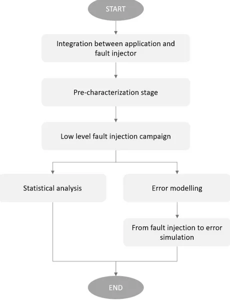
4 The Proposed Hybrid Cross-Layer Fault Injection Frame-work 35 4.1 Framework architecture and methodological flow . . . 35
4.1.1 Integration of the application with the fault injector . 38 4.1.2 Pre-characterization stage . . . 39
4.1.3 Low-level fault injection campaign . . . 40
4.1.4 Analysis stage . . . 41
4.2.1 Error model definition . . . 42
4.2.2 From fault injection to error simulation . . . 44
4.3 Advantages of the proposed approach . . . 46
5 Implementation of Fault Injection Framework 51 5.1 FPGA Fault Injector . . . 51
5.1.1 Overview of the fault injector . . . 51
5.1.2 Architecture of the fault injector . . . 52
5.1.3 Specific implementation details . . . 55
5.1.4 Fault injector execution flow . . . 58
5.1.5 Fault injection request . . . 60
5.1.6 Pre-characterization of synthesized filter . . . 62
5.1.7 Others framework implementations . . . 64
5.2 Additional framework tools . . . 64
6 Experimental Evaluation: Architecture-level Fault Injection 69 6.1 Experimental setup . . . 69 6.2 Filter pre-characterization . . . 72 6.3 Statistical analysis . . . 73 6.3.1 Gaussian filter . . . 75 6.3.2 Laplacian filter . . . 75 6.3.3 Sobel filter . . . 79 6.3.4 Sharpen filter . . . 79 6.3.5 Mean filter . . . 81 6.3.6 Median filter . . . 82
7 Experimental Evaluation: Error Modelling 87 7.1 Error models . . . 87
7.1.1 Error models definition . . . 88
7.1.2 Error models occurrences . . . 103
7.1.3 Input independence . . . 108
7.1.4 Time instant independence . . . 112
7.2 Error models validation . . . 112
7.2.1 Experimental setup . . . 113
7.2.2 Results . . . 113
7.3 Concluding remarks . . . 114
8 Conclusions 117 8.1 Future work . . . 119
B Hardware Implementations of FPGA Based Fault Injector 125
List of Figures
2.1 Example of image processing application . . . 8
2.2 Convolution example . . . 9
2.3 Mean filter kernel . . . 9
2.4 Mean filter example . . . 10
2.5 Gaussian filter kernel . . . 10
2.6 Gaussian filter example . . . 11
2.7 Laplacian filter kernel . . . 11
2.8 Laplacian filter example . . . 12
2.9 Sobel filter kernels . . . 13
2.10 Sobel filter example . . . 13
2.11 Sharpen filter kernel . . . 13
2.12 Sharpen filter example . . . 13
2.13 Salt and pepper noise . . . 15
2.14 Median filter example . . . 15
2.15 FPGA architecture . . . 16
2.16 Configurable Logic Block . . . 18
2.17 Switch box and switch matrix architectures . . . 18
2.18 Xilinx 7-Series FPGA DSP block . . . 19
3.1 Motivating fault examples . . . 30
3.2 Working scenario . . . 30
4.1 Hybrid cross-layer fault injector . . . 37
4.2 Methodological flow . . . 38
4.3 Examples of error models . . . 43
4.4 Complete overview of methodological flow . . . 48
4.5 Overall framework schema . . . 49
5.1 FPGA fault injector architecture . . . 53
5.2 Xilinx Virtex-7 FPGA VC707 Evaluation Board . . . 55
5.4 Fault injection framework execution flow . . . 61
5.5 LFA structure . . . 62
5.6 Activation sequence of used tools . . . 65
6.1 Input image . . . 70
6.2 Gaussian golden image . . . 70
6.3 Laplacian golden image . . . 70
6.4 Sobel golden image . . . 71
6.5 Sharpen golden image . . . 71
6.6 Mean golden image . . . 71
6.7 Median golden image . . . 71
6.8 Elaboration flow of images . . . 72
6.9 Gaussian: Faults overview . . . 76
6.10 Gaussian: Faults classification . . . 76
6.11 Gaussian: SDC overview . . . 76
6.12 Gaussian: Acceptable results . . . 76
6.13 Gaussian: SDC threshold classification . . . 77
6.14 Laplacian: Faults overview . . . 77
6.15 Laplacian: Faults classification . . . 77
6.16 Laplacian: SDC overview . . . 78
6.17 Laplacian: Acceptable results . . . 78
6.18 Laplacian: SDC threshold classification . . . 78
6.19 Sobel: Faults overview . . . 79
6.20 Sobel: Faults classification . . . 79
6.21 Sobel: SDC overview . . . 80
6.22 Sobel: Acceptable results . . . 80
6.23 Sobel: SDC threshold classification . . . 80
6.24 Sharpen: Faults overview . . . 81
6.25 Sharpen: Faults classification . . . 81
6.26 Sharpen: SDC overview . . . 81
6.27 Sharpen: Acceptable results . . . 81
6.28 Sharpen: SDC threshold classification . . . 82
6.29 Mean: Faults overview . . . 82
6.30 Mean: Faults classification . . . 82
6.31 Mean: SDC overview . . . 83
6.32 Mean: Acceptable results . . . 83
6.33 Mean: SDC threshold classification . . . 83
6.34 Median: Faults overview . . . 84
6.35 Median: Faults classification . . . 84
6.37 Median: Acceptable results . . . 84
6.38 Median: SDC threshold classification . . . 85
7.1 Examples of “Horizontal noise” model . . . 89
7.2 Examples of “Horizontal shift” model . . . 90
7.3 Examples of “Oblique noise” model . . . 92
7.4 Examples of “Oblique shift” model . . . 93
7.5 Examples of “Vertical noise” model . . . 94
7.6 Examples of “Completely corrupted” model . . . 95
7.7 Examples of filter interruption . . . 96
7.8 Examples of “Few pixels corrupted” model . . . 97
7.9 Examples of strong colours corruption . . . 98
7.10 Examples of weak colours corruption . . . 99
7.11 Examples of “Smashed image” model . . . 100
7.12 Examples of “Part of image corrupted” model . . . 101
7.13 Examples of “Random noise” model . . . 102
7.14 Gaussian fault models occurrences . . . 103
7.15 Laplacian fault models occurrences . . . 104
7.16 Sobel fault models occurrences . . . 105
7.17 Sharpen fault models occurrences . . . 106
7.18 Mean fault models occurrences . . . 107
7.19 Median fault models occurrences . . . 107
7.20 Input independence - Gaussian filter: “Vertical noise” and “Completely corrupted” wrong output . . . 109
7.21 Input independence - Gaussian filter: “Colours corrupted” wrong output . . . 110
7.22 Input independence - Laplacian filter: “Colours corrupted” wrong output . . . 111
7.23 Input independence - Laplacian filter: “Random noise” wrong output . . . 111
7.24 Example of results for the time instant independence experi-ments . . . 112
7.25 Setup of case study . . . 113
7.26 Error models occurrences . . . 114
B.1 PCAP and ICAP configuration . . . 128 B.2 Block design - Digilent Zybo Zynq-7000 Development Board . 129 B.3 Block design - Xilinx Virtex-7 FPGA VC707 Evaluation Board130
List of Tables
6.1 Number of essential bits . . . 72
6.2 Number of the extracted LFAs . . . 73
7.1 Gaussian fault models success rate . . . 109
7.2 Laplacian fault models success rate . . . 110
B.1 Available hardware resources . . . 126
B.2 SEM AXI memory mapped interface . . . 126
Chapter 1
Introduction
Digital computing systems are employed in every single activity of nowadays life. Depending on the working scenario and the application role, computing systems may assume a certain level of criticality for the success of the mission of the overall system they are integrated into and for the safety of people and systems they interact with. Indeed, a failure or a malfunctioning in safety-critical systems could threat the safety of people that are around it or working with it, cause the loss or severe damage to equipment or severely damage the environment. Automotive computing systems, devoted to assisting driving activities, such as autonomous driving, anti-lock braking system (ABS), Adaptive Cruise Control (ACC), Electronic Stability Control (ESC), are few examples of safety-critical systems, because a malfunctioning could pose a severe threat to the life of the passengers. On the other hand, a failure of a missicritical computing system, such as the satellite on-board one, may compromise the entire systems they are integrated to provide control or support capabilities, thus leading to a considerable monetary loss and further possible safety consequences.
Physical faults in the digital circuits are causes of failures and malfunc-tionings, especially in highly harsh environments. Digital systems are often subject to mechanical or thermal stress, or exposed to radiations; therefore, devices have higher chances to experience hard failures (i.e. permanent break down) or, with a higher frequency, soft errors (i.e. temporary memory state change or data corruptions). The overall effect of the faults affecting sys-tems is a possible deviation of the executed application from its nominal behaviour to an erroneous one, thus leading to the computation of a wrong result or even a system crash.
As a consequence, it is mandatory for mission-/safety-critical applica-tions to provide the desired level of reliability in the computation. To this
end, fault detection and management mechanisms, such as Duplication With Comparison (DWC) or Triple Modular Redundancy (TMR) are generally applied during the design of such types of systems to achieve the desired level of reliability [59, 42, 53, 60, 5, 35]. These techniques introduce addi-tional hardware/software parts not strictly related to the nominal function-ality. They have the role to recognize possible malfunctioning and correct them if it is possible. They make the system, within a certain limit, less vulnerable to fault effects. With the traditional fault prevention techniques, the hardware becomes more complex, such as the used resources, and not negligible overheads are introduced.
In the evolution of mission-/safety-critical systems, we may notice two main relevant trends: i) at architecture level a consolidated employment of reconfigurable devices, such as Field Programmable Gate Arrays (FPGAs), and ii) at application level a growing interest in using image processing also in mission-/safety-critical tasks.
FPGAs represent nowadays a very popular device for implementing any kind of hardware accelerator. Thanks to the reconfigurable capabilities, such a type of device presents a relevantly low design monetary cost and time-to-market with respect to the classical Application Specific Integrated Circuit (ASIC) implementation. Moreover, reconfiguration may be performed also at runtime and partially thus allowing a change/update of the hosted accel-erator or functionality; this capability even more increases FPGA potential-ities and attractiveness of their employment. As a matter of fact FPGAs are employed in computing systems for all application fields, spanning from commercial applications, e.g. data centres [15, 58] to mission-critical ones, such as military and space avionics [11, 12]; as a matter of fact the payload applications of satellites are generally hosted on FPGA devices. Unfortu-nately, the reconfiguration mechanism that makes FPGAs so versatile is also its point of weakness in safety-/mission-critical systems; the system config-uration is stored in a volatile memory, based on RAM technology, that is highly susceptible to soft errors [50], caused by radiations, i.e. Single Event Upsets (SEUs) [14]. More precisely, an alteration of the content in FPGA configuration memory leads not only in the corruption of processed data, as generally happens in ASIC circuits, but also to the change in the im-plemented functionalities. Differently from the corruption of the processed data that can be flushed at the subsequently processed data input, such a change presents permanent effects that require the configuration memory to be reprogrammed. When considering the large employment of FPGAs in satellites, the relevant presence of radiations in the harsh space environment rises such a necessity to introduce fault detection and tolerance mechanisms
to make such mission-critical systems reliable thus guaranteeing the correct behaviour.
On the other hand, there is a growing interest in using more and more advanced image processing applications for safety-/mission-critical systems. From the classical employments of image processing as payload application, for instance, on-board elaboration of acquired pictures on satellite systems, we have assisted to an evolution where image processing is exploited as an in-put of the control decisions of autonomous systems. Nowadays, autonomous driving is based on complex image processing pipelines [57, 28], integrating also machine learning algorithms [27, 25], to elaborate images acquired from the vehicle cameras and extract relevant information, such as the presence of pedestrian and obstacles, that can be used for instance to automatically ac-tivate the emergency braking system, thus avoiding accidents [49, 33, 43, 29]. Due to the necessity of more and more advanced capabilities, such image processing applications, generally composed of a sequence of basic filters, are reaching a considerable complexity and require a considerable amount of processing resources to guarantee the Quality of Service (QoS).
Therefore, FPGAs are a good candidate to accelerate such applications or parts of them. An example of the combination of FPGA and image processing is the employment in satellite applications [36]. Such applications collect pictures from a camera, apply a pipeline of manipulating filters and transmit the result to a base station on the Earth, which, in turn, will use the received data for its purposes.
In the discussed scenario considering image processing applications im-plemented onto FPGA devices, the design and hardening process to guar-antee the required reliability level of the safety-/mission-critical systems is actually a highly complex task. From one side, we have the high susceptibil-ity to soft errors of the FPGA devices and for the other one, the complexsusceptibil-ity of the image processing application.
One of the most relevant needs is the necessity to analyze the effect of the faults in a candidate implementation. Current practice on FPGA reliability evaluation, that is based on fault injection activities, requires the overall system (or the specific part of it to be hardened) to be fully implemented and deployed on the device to perform a reliability evaluation. This represents a relevant limitation due to the time to design for a hardware component not allowing fast feedback to the hardening process.
Nonetheless, such an analysis is not only required after the application of the hardening techniques (e.g. DWC or TMR) to assess if the achieved reliability level satisfies the requirements, but also before to evaluate the susceptibility to faults of the nominal application. In fact, image processing
presents an inherent resilience to the occurrence of faults due to the fact that i) input images may be noisy and some applications are by design able to deal with it, ii) a perfect error-free output is frequently not necessary to be able to correctly use it (e.g. when the end-user is a human, which is by nature not able to catch errors beyond a certain level of detail [37]), or iii) the output may be a probabilistic estimate and small errors are still considered tolerable [2]. Such resiliency may be potentially exploited to specifically tailor and tune the hardening process to the only critical components in the system thus considerably reducing the implementation costs. Unfortunately, such an opportunity can be difficulty exploited due to the lack of methods to analyze the reliability of an application in the early phases of the design flow, thus proving a fast feedback to the design activities.
1.1
Goals
The work presented in the thesis born from the necessity to realize an analy-sis framework specialized for complex image processing application providing controllability and observability. The goal of the framework is to provide a high-level analysis of system based on image processing implemented onto FPGA platform, that has a role to study the reliability and the error re-silience. The methodology is based on a Hybrid Cross-Layer fault injector that allows an analysis based on more levels of abstraction, in order to shift the analysis from the architectural perspective to the application level.
This paradigm shift allows us to have early feedback that considerably changes the classical project development flow, removing the needs to post-pone the analysis stage after that the architectural implementation is com-pleted.
The methodology purpose is strictly related to error models, that makes possible the abstraction of physical faults effects caused by soft errors on the image elaboration results.
A second contribute is the application of the designed methodological framework on a practical image processing application based on convolution filters. The objective is the characterization of fault models able to describe the error occurrences for the convolutional filter family. These models, after an accurate validation, could be used in future on more complex applications, by neglecting the dependencies that bind the application to the architectural implementations and so, by emulating the SEUs occurrences through the application-level error simulation.
1.2
Thesis outline
This thesis is organized as follows:
• Chapter 2 introduces the background of the considered scenario. It contextualizes our framework introducing the basic notions about im-age processing application, focusing in particular on the convolution filters family. Since our work regards the implementation of image pro-cessing through FPGA platform, also this topic is covered, discussing its architecture and the possible applications. Finally, a brief overview of the effect of soft errors in FPGA is presented. In the second part of the chapter, a review of the literature is introduced, to briefly discuss the past approaches in the considered context and their limitations which motivates our approach.
• Chapter 3 introduces the considered working scenario and highlights the limitations of the common practice approach in reliability analysis, widely used in the state of art approaches. The role of these limitations is to define requirements and necessities that motivate the definition of a novel methodological framework for hybrid fault injection in im-age processing applications implemented onto FPGA devices. More precisely, the last part of the chapter explains in a detailed way the thesis goal.
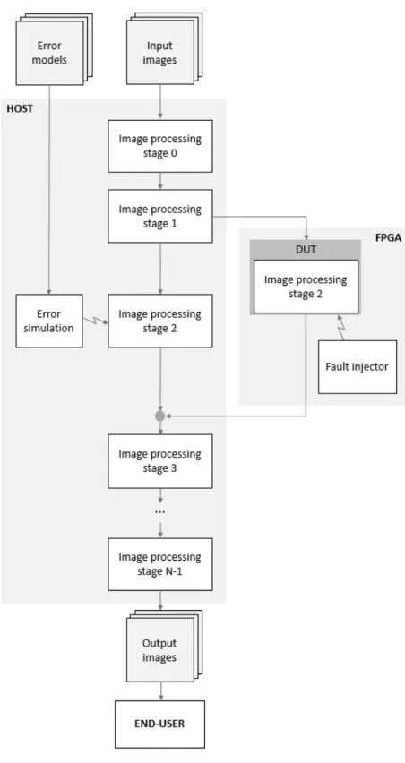
• Chapter 4 is the central part of the thesis presenting the proposed hybrid fault injection framework for image processing applications im-plemented onto FPGA. The framework is here shown at a functional level to describe the overall cross-layer approach to perform either low-level fault injection or high-level error simulation in the specific pipeline filters under design. The second part of the chapter discusses the methodology to abstract the effects of faults injected in the ar-chitecture, with the lower-level environment, in order to define error models to be integrated with the higher-level simulation environment. • Chapter 5 presents the details of the implementation of the hybrid fault injection framework. In particular, it describes the design and implementation of the low-level fault injector for FPGA and, later, the various tools defined for automating the methodological framework proposed in the previous chapter.
• Chapter 6 reports the application of the proposed hybrid fault injection framework in a case study. We have considered the widely used class
of convolution filters and we have performed a systematic low-level fault injection campaign; the results of this empirical phase covered in this chapter concerns a first superficial statistical analysis.
• Chapter 7 covers the definition of error models that can be integrated with the high-level error simulation environment and their validation. It introduces the case study specifically created to evaluate the error models and it quantifies the advantages replacing the fault injection procedure through the error simulation approach and the known error models, mostly in terms of saved time and design complexity.
• Chapter 8 draws the conclusions on the proposed work and envisions some future directions for the discussed research activity.
Finally, two additional chapters in the Appendix provide further technical and implementation details on the defined framework prototype:
• Appendix A reports the source code of the considered convolution algorithms employed in the experimental campaigns.
• Appendix B provides further implementation details on the fault in-jector implemented on the two considered prototyping boards (i.e. the Xilinx Virtex-7 FPGA VC707 Evaluation Board and the Digilent Zybo Zynq-7000 Development Board).
Chapter 2
Background and Related
Work
This chapter introduces the key aspects that are required to understand the proposed work in the thesis. Firstly, we present a general overview of the image processing application and a brief introduction to what is FPGA and its architecture. Next, we provide the basic notions of fault and errors, explaining in details what means Single Event Upset, also contextualizing it in FPGA platform. At the end of the chapter, we will provide an overview of the literature of past works, to discuss and analyze their limitations.
2.1
Image processing application
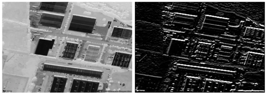
Digital image processing applications play an important role in our society every day, also thanks to the wide range of fields of application [1]. It is com-mon to find image processing in many environments, such as photography, artificial vision, industrial applications (e.g. product inspection), robotics, medical diagnosis, television, and many others. Generally, image process-ing can be defined as a software program that takes in input images and produces an elaboration and applies a specific effect on the output images. Figure 2.1 shows an example of image processing [45]. In the real world, these applications are used to apply a transformation and an improvement in the quality of the input image. In this case, the raw data constitutes the input taken from the sensor of a classic camera. Then, some operations are applied in a pipelined way and after the last elaboration, the image is ready to be displayed. The depicted pipeline shows a conventional consumer imaging pipeline, in which the first demosaicing operation is applied. Its role is to build a colour image from raw data. They are used by a sequence of
operations that improve the appearance of colours, brightness, edges and remove the eventual noise.
Figure 2.1: Example of image processing application
An important role in digital image processing is covered by filters [13]. These could be seen as a black box that takes in input one image, applies a transformation and produces an output image. These transformations applied by filters allow to characterize and improve images by applying par-ticular effects. For instance, in the real world, images could be affected by some noise that leads to unexpected variation of the data. To analyze a noisy image might be difficult, but some algorithm can be used to apply denoising and this is just an example of other existing transformations. An-other important category of filters is the edge detector, in which the edges of the image are emphasized. These identify image areas in which there are significant local changes. Edge detection is frequently the first step in re-covering information from images. There are many other effects types, such as sharpening, blurring, smoothing and so on.
Here we focus mainly on linear filter, particularly on those of convolution ones [48] since they will be the case study of this thesis. Such filters replace each pixel value by a linear combination of the pixel values close to the one considered based on the following mathematical function.
g(x, y) = w ∗ f (x, y) = a X s=−a b X t=−b w(s, t)f (x − s, y − t) (2.1) This expression is known as convolution. Each convolution filter is charac-terized by the kernel, also known as a mask or convolution matrix. Since each pixel is taken both its value and the value of its neighbours, these are multiplied by the convolution matrix and summed up. This process is repeated for the whole image.
This operation allows to extract some features from the input image; in this case, the kernel is named feature detector and the output is the feature
Figure 2.2: Convolution example
map. This is a key operation applied by the Convolutional Neural Network (CNN). An example of convolution operation is reported in Figure 2.2. The left matrix represents the input image and the middle one the kernel (in this case the edge detection convolution matrix is shown). The result is displayed in the right matrix. The highlighted cells show how the kernel matrix slides over the input image and produce the relative output value. In this way, the output image will result smaller than the input one, but some padding strategies have the role to assign a value to external pixels.
There are many types of convolution filters, the most important ones [44] are:
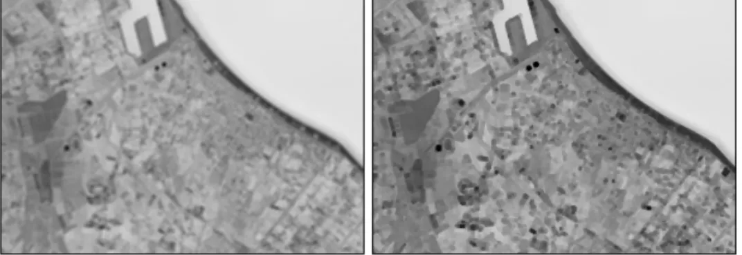
• Mean. This kind of filter replaces each pixel value with the average value of its neighbours. It applies an averaging effect and the output image appears slightly blurred. Mean filter is usually used to reduce the noise in images, removing pixel values which are not relevant with respect to the value of neighbours. To obtain the average of the neigh-bouring pixels, it is necessary to sum up all the values and to divide by the number of considered neighbours. Figure 2.3 shows exactly this aspect. Figure 2.4 depicts the effect applied by mean filter.
Figure 2.3: Mean filter kernel
• Gaussian blur. The objective of the Gaussian blur filter is the same as the mean one, that is to remove noise and details. But as opposed to the mean filter, it uses a different kernel that as can be seen from
Figure 2.4: Mean filter example
the related image represents the shape of Gaussian (Figure 2.5). In this type of filter, the degree of smoothing depends on both the kernel dimensions and the standard deviation. Using large standard devia-tion, it is required to have a large kernel to correctly represent the Gaussian.
The kernel reported in Figure 2.5 shows how this filter type gives more weight to the central elements. This is the biggest difference with the mean filter, that distributes the weights uniformly. In this way, the Gaussian can give to the image a blur effect while preserving better the edges. Figure 2.6 shows an example of the filter elaboration.
Figure 2.5: Gaussian filter kernel
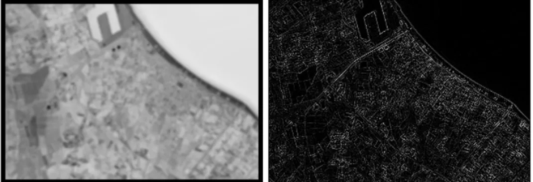
• Laplacian. The Laplacian filter is a specific kind of edge detector filter family. These filters have the role of highlighting the regions of an image that have a clear change in intensity or colour. High values mean sharp changes and low values mean few changes.
Laplacian applies a 2D isotropic measure of the second spatial deriva-tive of an image. This filter is very sensideriva-tive to noise and for this reason, the image needs to be smoothed by Gaussian or mean filter
Figure 2.6: Gaussian filter example
before being processed with Laplacian.
The input is related to the output by the following relation: L(x, y) = ∂
2I
∂x2 +
∂2I
∂y2 (2.2)
Since the input is a set of discrete inputs, a discrete convolution kernel that can approximate the above relation is necessary. An example of Laplacian kernel is reported in Figure 2.7, and Figure 2.8 shows the applied effect.
In a real application, usually, this filter is combined with Gaussian ones. Since this kernel is approximating a second derivative mea-surement on the image, the filter computation is highly sensitive to noise. As said before, before applying the edge detection effect it is fundamental to apply Gaussian blur transformation (to preserve edge better than the mean). For this reason, to find the two kernels merged is a very common approach. This operation creates the Laplacian of Gaussian operation (LoG) that requires only one convolution instead of two.
Figure 2.7: Laplacian filter kernel
• Sobel. It is another kind of edge detector filter. It is an approximation to an image derivative. The Sobel applies two derivatives, one for
Figure 2.8: Laplacian filter example
the x-direction and one along the y-direction. Each derivative uses a specific kernel, both are reported in Figure 2.9.
The Sobel operator produces two images in which it tries to find out the differences by placing and sliding the kernel on the image. These two images can be combined to find the absolute magnitude of the gradient and the orientation of that gradient. The gradient magnitude is computed using the following formula:
| G | =pGx2+ Gy2 (2.3)
that can be approximated for a faster computation in:
| G | = | Gx | + | Gy | (2.4)
Instead, the angle orientation of edge is given by: θ = arctanGy
Gx (2.5)
Figure 2.10 reports the effect applied by Sobel in the case of y-direction. Moreover, since the Sobel filter does not work on second-order deriva-tives, it results less sensitive to noise than Laplacian.
• Sharpen. This filter is widely used in photography. It allows to emphasize the details and enhance the edges of all the objects in the image but, on the other side, it is truly sensitive to noise. For this reason, in a complex image elaboration, it has to be the last step, or at least after the noise reduction filter. Both the kernel and the filter effect are reported in the Figures 2.11 and 2.12.
To better understand how convolution works, Algorithm 1 shows the translation of convolution operation into pseudocode. External loops allow
(1) x-direction (2) y-direction
Figure 2.9: Sobel filter kernels
Figure 2.10: Sobel filter example
Figure 2.11: Sharpen filter kernel
sliding among all pixels of the image, considering for one row at time all columns. Since zero padding is applied, if the considered pixel belongs to the image border, its value is automatically set to zero. Instead, the internal loops are dedicated to the kernel and the computation reported in Figure 2.2. After the pixel value is computed, a check on its value is necessary. If it is included in the grey-scale range values, it can be saved and the convolution goes on, otherwise, another check to assign the right values is applied.
Input: input image, kernel matrix Output: output image
begin
normalizationF actor ← value forall image rows do
forall image columns do if image border then
cellV alue ← 0 end
else
forall kernel rows do
forall kernel columns do cellV alue ←
cellV alue + kernelV alue ∗ inputCellV alue end
end
if cellV alue ∈ GrayscaleRange then outputCellV alue ←
cellV alue/normalizationF actor end
else
if cellV alue > M axGrayScaleV alue then outputCellV alue ← M axGrayScaleV alue ; else outputCellV alue ← minGrayScaleV alue ; end
end end end end
Algorithm 1: Convolution operation applied to images
algorithm is reported, specifying all technical details.
As said before, all filters already presented are linear. But in our exper-iments, we also used a nonlinear filter such as the median one. Just like a Gaussian blur and mean, the median filter is used to remove noise while preserving edges. It is particularly effective in removing “salt and pepper” noise. An instance of this classic image noise is reported in Figure 2.13.
Figure 2.13: Salt and pepper noise
Median filter is similar to the mean one, but it replaces each pixel value with the median value of the neighbouring pixels and not the average. The median value is computed by sorting in ascending order all the values of the neighbours and taking the middle one. An example of a median effect is reported in Figure 2.14
2.2
Field Programmable Gate Array
FPGA is a reconfigurable logic device made up by a grid of basic com-ponents connected through a routing net; both comcom-ponents and intercon-nection can be electronically programmed to get particular functionalities.
Figure 2.15: FPGA architecture
Figure 2.15 shows the overall architecture and introduces all the main com-ponents present in modern FPGAs.
Since it is a reconfigurable device, it means that FPGA is not designed for a single application like ASIC, but it makes possible the implementation of any hardware configuration simply by defining it through Hardware De-scription Languages (HDLs) such as VHDL and Verilog. Thus, flexibility is the key feature of FPGA and, for this reason, it has found a lot of uses in any computing system fields. Compared to the standard software imple-mentation that runs on Central Processing Units (CPUs), FPGA can reach better performance, also exploiting hardware optimization. The price to pay is the implementation time. Instead, compared to ASIC, FPGA can be used to design the same system, with the same functionalities, without spending time and money for the whole Integrated Circuit (IC) development process. These advantages imply some limits, mostly in terms of performance and energy consumption.
The FPGA reconfiguration means to change its functionalities. Just like installing new pieces of hardware that allow to run a new application. This can take place at any time when it is needed, also when the system is still running. FPGA is programmed by assigning a value for each configurable element in it. The file that contains all the configurable information is called bitstream. All information contained in it will be stored in the FPGA SRAM configuration memory. The most used technology is that of Xilinx based on SRAM [34], that is those we consider in this work.
is constituted by several blocks. Each of them can be programmed through the bitstream. Initially, the first FPGA provided only three programmable logical blocks: i) Configurable Logic Blocks (CLB), ii) Input Output Block (IOB), iii) Communication resources, and thanks to which was possible to implement any hardware configuration. On the modern FPGA, new com-ponents are added, mostly to provide more functionalities and reach better performance.
Configurable Logic Block
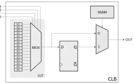
The CLBs represent the core of the FPGA and they allow to implement any kind of logic functionality, both combinational and sequential. This block is made up by a set of slices which in their turn are the set of Look-Up Tables (LUT).
In Xilinx 7-Series FPGA, the LUTs can implement any function com-posed of 6 inputs and 2 outputs. Configuring a LUT means storing a correct sequence of zeros and ones in the 16 memory cells. The memory cell lines are all connected to one multiplexer which allows reading the desired output by configuring the selectors.
As depicted in Figure 2.16, LUT is not the only element of CLB. In addition to this, there are one flip-flop D and another multiplexer. These two components allow to implement both the combinational and the se-quential logic. Flip-flop makes possible to store data coming from LUT (that implements the functionality) and the multiplexer allows to choose between the stored data (flip-flop) or the actual one provided by LUT, so it defines whether the implemented logic is sequential or combinational. The multiplexer selector is contained in SRAM, so it is set by the bitstream configuration.
Input Output Block
These elements have the role to interconnect an FPGA output pin to a signal of the internal logic. For each FPGA I/O pin exists one IOB that allows to establish both monodirectional and bidirectional communication.
Communication resources
They represent the physical connection between CLBs and IOBs. There are two types of interconnection: the direct one, which means that the data is put on the most appropriate channel depending on the destination, and the segmented one, which means that the communication is based on
Figure 2.16: Configurable Logic Block
interconnected lines using Switch Boxes (SBs). Figure 2.17 depicts this aspects. Each SB consists of several Switch Matrices (SMs). Each of these consists of six transistors that are used as logic switches and which allow to implement communication in all the possible directions.
(1) Switch box (2) Switch matrix
Figure 2.17: Switch box and switch matrix architectures
Further available resources
As previously said, modern FPGAs are not only composed of by CLBs, IOBs and SBs, but there are many other components. Among these, the Block-RAMs (BRAMs) and the Digital Signal Processors (DSPs) play an important role. The first allows implementing RAM, Read-Only Memories
(ROMs) and the buffer First In First Out (FIFO), while the second can be used to execute high-performance arithmetic computations.
DSPs are specific resources of the FPGA that are able to ensure better performance and less CLBs usage to implement arithmetic operations such as multiplications. Using CLB the hardware implementation of any multi-plication operation is made up by many adders and AND logic gates (e.g. a simple 4 bits multiplier requires about 403 LUTs). Instead, using a single DSP, the implementation of the same hardware operation will require fewer resources and will reach better performance. Each DSP is made up of some flip-flops, adder and multiplier, as Figure 2.18 reports.
Figure 2.18: Xilinx 7-Series FPGA DSP block
One of the most important functionality implemented by DSP is the Multiplier and Accumulator Unit (MAC). MAC covers a fundamental role in convolution operation, because it performs the product of two numbers and adds that product to an accumulator.
FPGA design flow
FPGA based system is designed through Register Transfer Level (RTL), that is a way to describe the circuit behaviour using signals, memory elements and logic operations. One way to create an RTL description is through hardware description languages, such as Verilog and VHDL.
Since we use a Xilinx FPGA in our work, we refer to the design flow expected by Vivado Design Suite. Low-level circuit descriptions are de-rived from the RTL, allowing the system to be transformed into a gate-level representation. Then, the place and route operations produce the physi-cal relationship between the designed system and the hardware platform. Finally, the bitstream will be generated.
tool, called Vivado HLS [22], that gives the ability to create an RTL de-scription starting from high-level languages, such as C/C++.
Once the system is ready, it is possible to develop the software that will run on the created hardware and that will make all the components interact with each other.
2.3
SEUs
Nowadays, with the digital system’s progress increasing more and more, aspects such as errors resilience and system reliability become central issues, especially in critical systems, as may be autonomous driving, autonomous emergency braking and more in general mission-/safety-critical real-time systems.
Faults occurrences can be related to many causes: bugs resulted from design errors, unexpected situations and technological limits. Related to the last aspect, examples of causes of failure are the semiconductor component size that has been strongly scaled and the use of power voltages that becomes lower and lower. Moreover, some systems are often subject to physical stress or they are placed in environments that are particularly prone to lead to faults. Such environments include, for example aeronautics and space systems, in which the adverse effects of radiations are much higher than on Earth and can cause an alteration of memory-data stored. So, the developing fault-tolerant techniques play crucial roles in the use of electronics in space.
We can coarsely categorize faults in three classes [6]:
• Permanent faults, characterized by irreversible changes.
• Intermittent faults, which do not affect the system permanently but they usually occur and cause hardware instability.
• Transient faults, which cause working error and malfunctioning in the system. They have temporary effects.
Faults induced by ionizing radiations, which are very common in aerospace applications [40], are usually referred to as Single Event Effects (SEE). These can be split into two categories: soft errors that lead to transient faults and hard errors, that cause permanent faults.
In our work, we focus on a subset of soft errors that are known as Single Event Upsets. SEU is a change in memory cell status caused by one single ionizing particle. From an electronic point of view, the SEUs consequences lead to temporary data corruption and loss in memories and flip-flops. They
do not cause any physical damage to the system [41], but the altering of information could be extremely dangerous, especially in mission-/safety-critical applications.
Due to the shrinking in size of transistors, the probability that SEU will induce memory cell to error increases. This is because smaller deposit charges are necessary to lead the transistor to an erroneous state [39].
Considering a generic application, SEUs may cause several effects: • Application crashes. The fault alters the value of a particular
con-trol variable/register that leads the program to an unexpected be-haviour, that results in a crash.
• Application timeouts. As in the previous case, the fault leads to a malfunction of the application behaviour. This time the program results in timeout and never end its operations.
• Silent Data Corruption. In this case, the application can success-fully conclude its execution but the generated output deviates from the right one [16, 32]. If any error-free output instance is not saved, determining if the computed output is correct or not becomes impos-sible. For this reason, these errors are potentially dangerous because they can bypass both hardware and software controls and alter the right behaviour of the system. Considering a mission-/safety-critical system this could lead to disastrous consequences. Thus, redundancy is the only solution that allows determining whether or not the result is affected by data corruption.
When considering a system fully-implemented on SRAM-based FPGAs, SEUs make them unreliable processing platform. Indeed, SEUs are a major cause of malfunction in modern FPGAs [18]. In the last years, FPGAs have also been widely used in aerospace applications. Indeed, the functional ver-satility, the high performance, the low power consumption and mostly the reconfiguration features make the FPGAs perfect for this kind of applica-tions. So, their use in the space system and the satellite continues to grow. On the other hand, SRAM-based FPGAs are not designed for working in the space environment and they are truly susceptible to ionizing radiations [51]. SEUs apply to FPGA an unintentional change to the state of a configu-ration memory bit. This causes unacceptable changes in design behaviour, changing its functionalities. As already said, the errors associated with SEUs are usually not destructive towards system integrity and they can be simply recovered rewriting the original memory configuration. Based on the above, to design a fault-tolerant system on FPGA is a great challenge.
2.4
Related work
When a new system is developed and it is ready to be used in a critical environment, it is necessary to analyze the effects of faults that may occur and lead to malfunctioning. Fault injection is a way to inject errors and emulate the SEUs impact on the analyzed system. This is an experimental procedure that allows studying the system availability and error resilience. It provides the possibility to understand which are the critical aspects and whether it is possible to build both a fault-tolerant system and mitigation methodologies able to reduce the fault effects or not [47, 52, 38]. For this reason, in the last years, the scientific community had a particular interest in fault injection topics.
The literature about fault injector is huge, but we focus only on the specific scenario of the image processing application based on FPGA. In this context, we found two literature directions: the first one regards the fault injector implementation based on FPGA platform and the second one concerns the functional injector applied to image processing.
2.4.1 FPGA based fault injector
This research line focuses mainly on the hardware implementation of the fault injector on FPGA, paying close attention to implementation details, such as the architecture and the right working. Generally, this research applies a classic statistical analysis of the gathered results.
In particular, we focus on the advantages and limitations of these imple-mentations, which are the aspects in common with our framework and the limits that we want to overcome.
On the Reliability of Convolutional Neural Network Implementa-tion on SRAM-based FPGA
An interesting framework is the one proposed in [7]. It focuses on image recognition and analyzes the reliability of one CNN implemented on FPGA that processes an image provided by a camera. The application field is the autonomous driving and, in particular, pedestrian recognition, that is an evident example of safe-critical application. The captured image is sent to CNN and it categorizes if a pedestrian is present or not. During the classification, procedure faults are injected and the effects are then analyzed. The fault injection platform aims to emulate SEU in configuration memory by generating a faulty bitstream with selected bit(s) in frame data flipped. The bitstream manipulation is handled through host PC and then loaded in
Xilinx Pynq-Z1 board. Faults are injected in bit related to BRAM, registers, DSP and LUT. In this study, the goal is to test the susceptibility of FPGA hardware resources, understanding which of them is more prone to lead to SDC. The results obtained allow understanding that DSP and LUT are the two most susceptible elements to injected faults.
Analyzing the resilience to SEUs of an image data compression core in a COTS SRAM FPGA
In [56], another FPGA-based injector is presented. In this research, the error resilience of the image compression process is evaluated. Soft errors are classified in terms of the effects produced in the compression operation and in the quality of the reconstructed image, using a specific metric. As the previous framework, the fault injector architecture is composed by the host PC and FPGA platform. In FPGA, a hardware accelerator for data compression is implemented and its functionality is the image compression algorithm. During the image elaboration, the host sends an injection request to the FPGA. After that the image elaboration is terminated, the output is decompressed and compared with the initial one. The degradation metric is calculated from the decompressed image and the final results report only how much the injected faults affected the compression procedures.
Fault Injection In Dynamic Partial Reconfiguration Designed Based on Essential Bits
FPGA-based injector can be used for many purposes. In [26], a system very similar to our fault injector is presented. In this case, a Kintex-7 FPGA is used and the injection campaign is performed on a particular design called Dynamic Partial Reconfiguration Design (DPRD). It consists of two parti-tions, one static and one dynamic (reconfigurable). The Xilinx Intellectual Property (IP) called Soft Error Mitigation (SEM) is used to inject faults. In this study, the injector is the means to perform the injection on both regions, static and dynamic, and to study the advantages of using Xilinx Essential bit in terms of reducing the time of error injection process.
Injecting FPGA Configuration Faults in Parallel
Another case study is presented in [10]. It focuses on the implementation of the fault injection framework based on reconfigurable platforms that have met the challenges of scalability, reliability and flexibility. The implemented injector is used to perform a campaign on image clustering application,
where during the processing of the application a bit-flip occurred and led to alteration of the output. The injector is made up by seven Digilent Zedboard, characterized by Xilinx Zynq device, on which Linux OS runs. Also, in this case, the injections are performed using Xilinx SEM IP. The corrupted outputs are evaluated through the use of Structural SIMilarity (SSIM) metric, that allows representing the alteration intensity from the original image.
To sum up, we can state that these research pay a lot of attention to the technical implementation of the fault injector. Indeed it focuses on a standard framework implementation of the FPGA based fault injection platform.
Generally, these papers do not focus on an in-depth application-oriented analysis but on a high-level meaning. Many of them perform classic statis-tical analysis on the final outputs of the system under design, such as create a statistic about the obtained fault and errors classification. Instead, oth-ers perform a physical analysis, focusing on what happens to the system’s functionalities when a SEU occurs.
Moreover, these approaches present another limitation; the application under consideration is a simple small one. This is due to the fact that the FPGA fault injectors have generally limited resources that cannot support the integration of both the injection facility and a large system under test. In addition, the development time to integrate everything in the same FPGA is generally unaffordable. In conclusion, such approaches strongly limit the applicability of this reliability analysis in many fields of applications.
2.4.2 System level analysis and fault injection framework In literature there is another direction that allows studying fault injection framework from another perspective, that is a focus on analysis more ori-ented to the application scenario, mostly image processing. Examples of these study use the Low-Level Virtual Machine (LLVM) [30] fault injector to inject errors in an Intermediate Representation (IR) code, that is a higher level than the assembly code [17]. Low-Level Fault Injection (LLFI) injects errors to the IR and the execution of the program may change abnormally. These research focus on the application itself and not pay much attention to the injection architecture. Despite the injected errors are still based on low-level aspects, such as instructions and program flow alteration, the focus of these papers is the application-level analysis.
LLFI: An Intermediate Code Level Fault Injector For Soft Com-puting Applications
In [54], the application subject to faults injection is an example of a soft computing application that handles images. During handling, faults are in-jected using LLFI and the outcomes only regard the relationship between occurred effects and the types of data affected by faults. The research analy-sis focuses mostly on the classification of corrupted output in two categories: Egregieous Data Corruptions (EDC) which are application results that de-viate significantly from the fault-free outcomes and Non-EDCs, which are results with a small deviation in output. The classification is performed through a fidelity metric. Moreover, the study creates a relationship be-tween the instruction types (control and pointer) subject to the injection and the generated errors. This information helps an application-oriented analysis based on the identification of detector placement locations in code (software redundancy).
Error Detector Placement for Soft Computing Applications The same topic is covered by [55], where through LLVM a fault injection campaign is performed during an image processing application and the faults are classified in: i) EDC, ii) Non-EDC, iii) Benign, and iv) Crash. Based on gathered information, an algorithm that allows to identify the code location where to place high coverage detectors is created. Thus, also in this case, we can find two kinds of analysis, the first focuses on the fault classification and the second is oriented towards the application scenario, that aims to improve the availability of the program.
Understanding Error Propagation in Deep Learning Neural Net-work (DNN) Accelerators and Applications
In [32], there is another example of a digital system and application is sub-ject to the fault insub-jection study. This time, a Deep Neural Network used in safety-critical systems such as self-driving cars is deeply analyzed, mostly to understand the effect of SEU on the final output. In such a scenario, a soft error can lead to misclassification of objects, resulting in wrong action taken by the car. Since the injection on RTL implementation of DNN is not possible, a DNN simulator is used and the hardware resources are mapped to the relative line of code in the simulator. The faults are randomly in-jected into the different code lines, so as to have an impact on the related microarchitectural components. The ultimate purpose of the research is
de-termining the availability and susceptibility of DNN architecture subject to soft errors and understanding the connections between the found SDCs and the characterizing application parameters, such as data types, values and reuse. Once this information is ready, it will assist for a further analysis which goal is to define guidelines for designing resilient DNN systems and propose protection techniques to mitigate soft errors.
Evaluation of Histogram of Oriented Gradients Soft Errors Criti-cality for Automotive Applications
A similar research to [32] is presented in [9]. Also in this case, the studied application is the autonomous or aided driving, but this time it is imple-mented on Graphics Processing Units (GPUs) and exploits a method that uses Histogram of Oriented Gradients (HOGs). The most interesting as-pect about this research is that it goes a step beyond the traditional SDCs detection by considering the criticality of errors. Besides measuring the number of radiation-induced output errors, different metrics will be identi-fied. These provide important information about the effects of the SDC on pedestrian recognition application. Furthermore, it aims to characterise ra-diation impact on HOG execution, i.e., how the number of Bounding Boxes (BBs), their position, and proprieties are affected by radiations compared to a radiation-free execution. So, besides the classic errors evaluation, it focuses on the usability of the output results. Moreover, the fault injection campaign results highlight the most critical procedures for HOG. Those procedures are exactly the ones that should be hardened, eventually with duplications.
These research try to abstract towards the level application all the low-level details, so several error models are defined, but these are still linked to the single application instruction, so tied to the micro-architectural level and not to the application one. Moreover, some of these (as in the case of [9]) are not completely validated, so the risk consists in having error models that are not able to characterize the real error effects. Furthermore, all of these works focusing on application-level analysis are realized for CPU or GPU hardware platform, none of them realizes an analysis framework based on FPGA.
Thus, considering the mentioned research, it is easy to understand that there are premises for building a general methodological framework for fault injection, but it is not designed yet. For this reason, in the thesis, we suggest
an injection framework that merges all the analyzed aspect and it focuses on the availability analysis through advanced tools.
This chapter introduced all the key concepts that cover an important role in the thesis. We discussed the image processing application to understand in which context is placed our thesis work and the FPGAs platforms. We also reported the baseline about SEUs, describing which are the effects they cause. Finally, we introduced the related works, analyzing which are the strengths and weakness. The next chapter will introduce and contextualize the proposed framework.