The
Eur
o
p
e
an
Uni
o
n
I
n
or
de
r
t
o
pr
omot
e
publ
i
c
e
duc
a
t
i
on
a
nd
publ
i
c
s
a
f
e
t
y,
e
qua
l
j
us
t
i
c
e
f
or
a
l
l
,
a
be
t
t
e
r
i
nf
or
me
d
c
i
t
i
ze
nr
y,
t
he
r
ul
e
of
l
a
w,
wor
l
d
t
r
a
de
a
nd
wor
l
d
pe
a
c
e
,
t
hi
s
l
e
ga
l
doc
ume
nt
i
s
he
r
e
by
ma
de
a
va
i
l
a
bl
e
on
a
nonc
omme
r
c
i
a
l
ba
s
i
s
,
a
s
i
t
i
s
t
he
r
i
ght
of
a
l
l
huma
ns
t
o
know
a
nd
s
pe
a
k
t
he
l
a
ws
t
ha
t
gove
r
n
t
he
m.
≠
EDI
CT
OF
GOVERNMENT
±
EN 1993-1-5 (2006) (English): Eurocode 3: Design of steel
structures - Part 1-5: General rules - Plated structural
elements [Authority: The European Union Per Regulation
305/2011, Directive 98/34/EC, Directive 2004/18/EC]
NORME EUROPEENNE
EUROpAISCHE NORM
October 2006ICS 91.010.30; 91.080.10 Supersedes ENV 1993-1-5:1997 Incorporating corrigendum April 2009
English Version
Eurocode 3 - Design of steel structures - Part 1-5: Plated
structural elements
Eurocode 3 - Calcul des structures en acier Partie 1-5: Plaques planes
Eurocode 3 Bemessung und konstruktion von Stahlbauten Teil 1-5: Plattenbeulen
This European Standard was approved by CEN on 13 January 2006.
CEN members are bound to comply with the CEN/CENELEC Internal Regulations which stipulate the conditions for giving this European Standard the status of a national standard without any alteration. Up-to-date lists and bibliographical references concerning such national standards may be obtained on application to the Central Secretariat or to any CEN member.
This European Standard exists in three official versions (English, French, German). A version in any other language made by translation under the responsibility of a CEN member into its own language and notified to the Central Secretariat has the same status as the official versions.
CEN members are the national standards bodies of Austria, Belgium, Cyprus, Czech Republic, Denmark, Estonia, Finland, France, Germany, Greece, Hungary, Iceland, Ireland, Italy, Latvia, Lithuania, Luxembourg, Malta, Netherlands, Norway, Poland, Portugal, Romania, Slovakia, Slovenia, Spain, Sweden, Switzerland and United Kingdom.
EUROPEAN COMMITTEE FOR STANDARDIZATION COMITE EUROPEEN DE NORMALISATION EUROP,.1.ISCHES KOMlTEE FOR NORMUNG
Management Centre: rue de Stassart, 36 B-1050 Brussels
© 2006 CEN All rights of exploitation in any form and by any means reserved worldwide for CEN national Members.
EN 1993-1-5:2006 (E)
Content
1 Introduction 1.1 Scope
1.2 N ormati ve references 1.3 Terms and definitions 1.4 Symbols
2 Basis of design and nlodelling 2.1 General
2.2 Effective width models for global analysis 2.3 Plate buckling effects on uniform members 2.4 Reduced stress method
2.5 Non uniform members
2.6 Members with corrugated webs 3 Shear lag in 1l1ember design
3.1 General
3.2 Effective~ width for elastic shear 3.3 Shear lag at the ultimate limit state
4 Plate buckling effects due to direct stresses at the ultimate limit state 4.1 General
4.2 Resistance to direct stresses 4.3 Effective cross section
4.4 Plate elements without longitudinal stiffeners 4.5 Stiffened plate elements with longitudinal stiffeners 4.6 Verification
5 Resistance to shear 5.1 Basis
5.2 Design resistance
5.3 Contribution from the web 5.4 Contribution from flanges 5.5 Verification
6 Resistance to transverse forces 6. J Basis
6.2 Design resistance 6.3 Length of stiff bearing
6.4 Reduction factor
XF
for effecti ve length for resistance 6.5 Effective loaded length6.6 Verification 7 Interaction
7.1 Interaction between shear force, bending moment and axial force 7.2 Interaction between transverse force, bending moment and axial force 8 Flange induced buckling
9 Stiffeners and detailing 9.1 General 9.2 Direct stresses 9.3 Shear 9.4 Transverse loads
Page
S 55
5
6 7 7 7 7 8 8 8 9 9 9 1213
13 13 l3 IS 18 2121
21 22 22 25 252S
25 26 26 27 27 2828
28 2929
30 30 30 3435
Annex B (informative) Non uniform members
Annex C (informative) Finite Elenlent Methods of Analysis (FEM)
Annex D (informative) Plate girders with corrugated webs
EN 1993-1-5:2006 (E)
43 45
50
EN 1993-1-5:2006 (E)
Foreword
This European Standard EN 1993-1-5" Eurocode 3: Design of steel structures Part 1.5: Plated structural elements, has been prepared by Technical Committee CENITC250 « Structural Eurocodes », the Secretariat of which is held by BSI. CEN/TC250 is responsible for all Structural Eurocodes.
This European Standard shall be given the status of a National Standard, either by publication of an identical text or by endorsement, at the latest by April 2007 and conflicting National Standards shall be withdrawn at latest by March 20
1 O.
This Eurocode supersedes ENV 1993-1-5.
According to the CEN-CENELEC Internal Regulations, the National Standard Organizations of the fol1owing countries are bound to implement this European Standard: Austria, Belgium, Cyprus, Czech Republic, Denmark, Estonia, Finland, France, Germany, Greece, Hungary, Iceland, Ireland, Italy, Latvia, Lithuania, Luxembourg, Malta, Netherlands, Norway, Poland, Portugal, Romania, Slovakia, Slovenia, Spain, Sweden, Switzerland and United Kingdom.
National annex for EN 1993-1-5
This standard gives alternative procedures, values and recommendations with notes indicating where national choices may have to be made. The National Standard implementing EN 1993-1-5 should have a National Annex containing all Nationally Determined Parameters to be used for the design of steel structures to be constructed in the relevant country.
National choice is allowed
in
EN 1993-1-5 through: 2.2(5) 3.3( 1) 4.3(6) 5.1 (2) 6.4(2) 8(2) 9.1 (I) 9.2. 1(9) 10(1 ) 10(5) C.2( 1) C.5(2) C.8(1) C.9(3) D.2.2(2)EN 1993-1-5:2006 (E)
1 Introduction
1.1 Scope
(1) EN 1993-1-5 gives design requirements of stiffened and unstiffened plates which are subject to in-plane forces.
(2) Effects due to shear lag, in-plane load introduction and plate buckling for I-section girders and box girders are covered. Also covered are plated structural components subject to in-plane loads as in tanks and silos. The effects of out-of-plane loading are outside the scope of this document.
NOTE 1: The rules in this part complement the rules for class I, 2, 3 and 4 sections, see EN 1993-1 I.
NOTE 2: For the design of slender plates \vhich are subject to repeated direct stress and/or shear and also fatigue due to out-of-plane bending of plate elements (breathing) see EN 1993-2 and EN 1993-6.
NOTE 3: For the effects of out-of-plane loading and for the combination of in-plane effects and out-or-plane loading effects see EN 1993-2 and EN 1993-1-7.
NOTE 4: Single plate elements may be considered as /lat where the curvalUre radius r satisfies:
a
r?:. t
where a is the panel width is the plate thickness
1.2 Normative references
(I.I )
(1) This European Standard incorporates, by dated or undated reference, provIsIons from other
publications. These normative references are cited at the appropriate places in the text and the publications are listed hereafter. For dated references, subsequent amendments to or revisions of any of these publications apply to this European Standard only when incorporated in it by amendment or revision. For undated references the latest edition of the publication referred to applies.
EN 1993-1 1 Eurocode 3 :Design o.fsteel structures: Part 1-1: General rules and rilles for buildings
1.3 Terms and definitions
For the purpose of this standard, the following terms and definitions apply:
1.3.1
elastic critical stress
stress in a component at which the component becomes unstable when using small deflection elastic theory of a perfect structure
1.3.2
membrane stress
stress at mid-plane of the plate
1.3.3
gross cross-section
the total cross-sectional area of a member but excluding discontinuous longitudinal stiffeners
1.3.4
effectiYe cross-section and effective width
the gross cross-section or width reduced for the effects of plate buckling or shear between their effects the word "effective" is clarified as follows:
"effectiveP" denotes effects of plate buckling
EN 1993-1-5:2006 (E)
"effective'" denotes effects of shear lag
"effective" denotes effects of plate buckling and shear lag 1.3.5
plated structure
a structure built up from nominally flat plates which are connected together~ the plates may be stiffened or unstiffened
1.3.6
stiffener
a plate or section attached to a plate to resist buckling or to strengthen the plate; a stiffener is denoted: longitudinal if its direction is parallel to the member;
transverse if its direction is perpendicular to the member. 1.3.7
stiffened plate
plate with transverse or longitudinal stiffeners or both 1.3.8
subpanel
unstiffened plate pOliion surrounded by flanges and/or stiffeners 1.3.9
hybrid girder
girder with flanges and web made of different steel grades; this standard assumes higher steel grade
in
flanges compared to webs 1.3.10
sign convention
unless otherwise stated compression is taken as positive
1.4 Symbols
(I) In addition to those given in EN 1990 and EN 1993-1-1, the following symbols are used:
A,f total area of all the longitudinal stiffeners of a stiffened plate;
As! gross cross sectional area of one transverse stiffener;
Aeff effective cross sectional area; Ac.e1l effectiveP cross sectional area;
effectiveP cross sectional area for local buckling;
a length of a stiffened or unstiffened plate;
b width of a stiffened or unstiffened plate;
bw ~clear width between welds for welded sections or between ends of radii for rolled sections; @il berr effective' width for elastic shear lag;
Fr~d design transverse force;
hw c lear web depth between flanges;
Len effective length for resistance to transverse forces, see 6;
A1u<d design plastic moment of resistance of a cross-section consisting of the flanges only; Mpl.Rd design plastic moment of resistance of the cross-section (irrespective of cross-section class);
VEd design shear force including shear from torque;
Wen effective elastic section modulus:
fJ
effectiveSwidth factor for elastic shear lag;
(2) Additional symbols are defined where they first occur.
2 Basis of design and modelling
2.1
General
EN 1993-1-5:2006 (E)
(J)P The effects of shear lag and plate buckling shall be taken into account at the ultimate, serviceability or fatigue limit states.
NOTE: Partial factors /1.;10 and }<.,11 used in this part are defined for different applications in the National Annexes of EN 1993-1 to EN 1993-6.
2.2 Effective width models for global analysis
(])P The effects of shear lag and of plate buckling on the stiffness of members and joints shall be taken into account in the global analysis.
(2) The effects of shear lag of flanges in global analysis may be taken into accollnt by the use of an effectiveS
width. For simplicity this effectiveS
width may be assumed to be uniform over the length of the span.
(3) For each span of a member the effectiveS
width of flanges should be taken as the lesser of the full width and
LI8
per side of the web, where L is the span or twice the distance from the support to the end of a cantilever.(4) The effects of plate buckling in elastic global analysis may be taken into account by effectiveP cross
sectional areas of the elements in compression, see 4.3.
(5) For global analysis the effect of plate buckling on the stiffness may be ignored when the effectiveP
cross-sectional area of an element in compression is larger than Plilll times the gross cross-sectional area of
the same element.
NOTE 1: The parameter Ptim may be given in the National Annex. The value Ptilll = 0,5 is recommended. NOTE 2: For determining the stiffness when (5) is not fulfilled, see Annex E.
2.3 Plate buckling effects on uniform members
(1) EffectiveP width models for direct stresses, resistance models for shear buckling and buckling due to transverse loads as well as interactions between these models for determining the resistance of uniform members at the ultimate limit state may be used when the following conditions apply:
panels are rectangular and flanges are paralle1;
the diameter of any llf1stiffened open hole or cut out does not exceed O,05b, where b is the width of the panel.
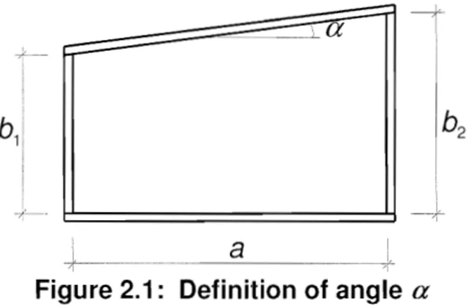
NOTE: The rules may apply to non rectangular panels provided the angle alil11il (see Figure 2.1) is not greater than 10 degrees. If Ulimil exceeds 10, panels may be assessed assuming it to be a rectangular panel based on the larger of hi and
h.
of the panel.EN 1993-1-5:2006 (E)
a
Figure 2.1: Definition of angle
a
(2) For the calculation of stresses at the serviceability and fatigue limit state the effectiveS
area may be used if the condition in 2.2(5) is fillfilled . For ultimate 1imit states the effective area according to 3.3 should be lIsed with
j3
replaced by j3ull'2.4 Reduced stress method
(1) As an alternative to the use of the effectiveP width models for direct stresses given in sections 4 to 7 ~ the cross sections may be assumed to be class 3 sections provided that the stresses in each panel do not exceed the Ii mits specified in section 10.
NOTE: The reduced stress method is analogous to the effectiveP width method (see for single plated elements. However, in verifying the stress limitations no load shedding has been assumed between the plated elements of the cross section.
2.5 Non uniform members
(]) Non uniform members haunched members, non rectangular panels) or members with regular or
irregular large openings may be analysed llsing Finite Element methods.
NOTE 1: See Annex B for non uniform members. NOTE 2: For FE-calculations see Annex C.
2.6
Members with corrugated webs
(1) For members with corrugated webs, the bending stiffness should be based on the flanges only and webs should be considered to transfer shear and transverse loads.
NOTE: For ~ text deleted @1) buckling resistance of llanges in compression and the shear resistance of webs see Annex D.
EN
1993-1-5:2006 (E)
3 Shear lag in member design
3.1
General
(1) Shear lag in flanges may be neglected if bo < L,/50 where bo is taken as the flange outstand or half the width of an internal element and Lt, is the length between points of zero bending moment, see 1 (2).
(2) Where the above limit for bo is exceeded the effects due to shear lag in flanges should be considered at serviceability and fatigue limit state verifications by the use of an effective' width according to 3.2.1 and a stress distribution according to 3.2.2. For the ultimate limit state verification an effective area according to 3.3 may be used.
(3) Stresses due to patch loading in the web applied at the flange level should be determined from 3.2.3.
3.2 Effective
Swidth for elastic shear lag
3.2.1
IR1)Effectives width
@l)(1) The effective' width for shear lag under elastic conditions should be determined from:
(3.1 )
where the effective' factor f3 is given in Table 3.1.
IR1) This effective' width may @l) be relevant for serviceability and fatigue limit states.
(2) Provided adjacent spans do not differ more than 50% and any cantilever span is not larger than half the
adjacent span the effective lengths
Le
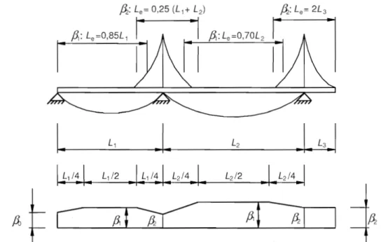
may be determined from Figm'e 3.1. For all other cases should be taken as the distance between adjacent points of zero bending moment.I.
L1J
L2.I.
L3.1
\l1/!1.
L1/2 .ll1 I!I.
L2/4.1.
L2/2.. I.
L2/4 .. II
ftl
~
fil
~I
Figure 3.1: Effective length
Le
for continuous beam and distribution of
effective
Swidth
EN 1993-1-5:2006 (E)
K K:S 0,02 0,02 < K:S 0,70 >0,70 I for/lange olltstand 2 for internalflange 3 plate thickness t4 st(fleners with Asl
=
L
AVliFigure 3.2: Notations for shear lag
Table 3.1: Effective
Swidth factor
f3
VerificationfJ -
valuefJ
1,01
sagging bendingfl
=
fll
=
1 + 6,4
K2
fl fl2=
hogging bending 1 11
+
6,0 (
2500
fl
1
sagging bendingfll
=
5,9
K1
hogging bendingfl
fl2
=
8,6
K
:) +
1,6
K2all K end support
Po
(0,55 + 0,025 / K)PI,
butPo
< PIall K Cantilever
Ii :::::
P2
at support and at the endK
au
bo /
Le witha
o1+
hot
in which Asr is the area of all longitudinal stiffeners within the width bo and other symbols are as defined in Figure 3.1 and Figure 3.2.
3.2.2 Stress distribution due to shear lag
EN 1993-1-5:2006 (E)
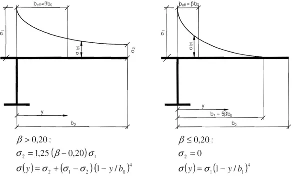
(]) The distribution of longitudinal stresses across the flange plate due to shear lag should be obtained from Figure 3.3. y
fJ>
0,20:
(J2
=
1,25
(fJ -
0,20)
(JI
(J(Y) (J2
+((Jj
(J2)(1
y/hot
yfJ
~0,20:
(J2
=
°
bo(J(y)
=
(Jj
(I -
Y /
hI
t
0"1 is calculated ~ with the effectiveS width @i] of the flange hefr
Figure 3.3: Distribution of stresses due to shear lag
3.2.3
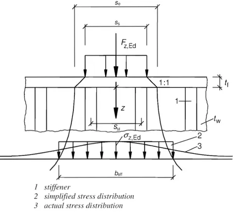
In-plane load effects(1) The elastic stress distribution in a stiffened or unstiffened plate due to the local introduction of in-plane forces (patch loads), see Figure 3.4, should be determined from:
(3.2)
with: =
se
1+ -"'-
l
7J2
se
11n 0,636
1
+
0,878
aI_II..
tilwhere ast.1 is the gross cross-sectional ~ area of the directly loaded stiffeners divided@i] over the length St:.
This may be taken as the area of a stiffener smeared over the length of the spac ing Sst; @i]
tw is the web thickness;
f.. is the distance to flange.
~ Se is the length of the stiff beating;
Sst is the spacing of stiffeners; @i]
NOTE: The equation (3.2) is valid when neglected.
EN 1993-1-5:2006 (E)
Se
Ss
S,Ed
I stiffener
2 siTnpl(fied stress distribution 3 actual stress distriblltion
Figure 3.4: In-plane load introduction
NOTE: The above stress distribution may also be used for the fatigue verification.
3.3 Shear lag at the ultimate limit state
(I) At the u1timate 1imit state shear lag effects may be determined as foHows:
a) elastic shear Jag effects as determined for serviceability and fatigue limit states, b) combined effects of shear Jag and of plate buckling,
c) elastic-plastic shear lag effects allowing for limited plastic strains.
NOTE 1: The National Annex may choose the method to be applied. Unless specified otherwise in EN 1993-2 to EN 1993-6, the method in NOTE 3 is recommended.
NOTE 2: The combined effects of plate buckling and shear lag may be taken into account by by:
Aeff as given
(3.3) where Auf! is the effectiveP area of the compression flange due to plate buckling (see 4.4 and 4.5);
ftull is the effectiveS width fac\or for the effect of shear lag at the ultimate limit state, which may be
taken as ~ determined from Table 3.1 with QD replaced by
(3.4)
EN 1993-1-5:2006 (E)
NOTE 3: Elastic-plastic shear lag effects allowing for lirnited plastic strains may he taken into accounl using
as follows:
(3.5)
where
,B
and Kare taken from Table 3.1.The expressions in NOTE 2 and NOTE 3 may also be applied for flanges in lension in which case replaced by the gross area of the lension tlange.
should be
4 Plate buckling effects due to direct stresses at the ultimate limit state
4.1
General
(1) This section gives rules to account for plate buckling effects from direct stresses at the ultimate limit state when the following criteria are met:
a) The panels are rectangular and flanges are parallel or nearly parallel (see 2.3); b) Stiffeners,
if
any, are provided in the longitudinal or transverse direction or both; c) Open holes and cut outs are small (see 2.3);d) Members are of uniform cross section~
e) No flange induced web buckling occurs.
NOTE 1: For compression !lange buckling in the plane of the web see scclion 8.
NOTE 2: For stiffeners and delailing of plated members subject to plate buckling see scclion 9.
4.2 Resistance to direct stresses
(1) The resistance of plated members may be determined ~using the effectiveP areas@j] of plate elements
in compression for class 4 sections lIsing cross sectional data fell, Wen) for cross sectional verifications
and member verifications for column buckling and lateral torsional buckling according to EN 1993-1 I.
(2) EffectiveP areas should be determined on the basis of the linear strain distributions with the attainment
of yield strain in the mid plane of the compression plate.
4.3 Effective cross section
(I) In calculating longitudinal stresses, account should be taken of the combined effect of shear lag and plate buckling lIsing the effective areas given in 3.3.
(2) The effective cross sectional properties of members should be based on the effective areas of the
compression elements and on the effectiveS
area of the tension elements due to sllenr lag.
(3) The effective area Aeff should be determined assuming that the cross section is subject only to stresses
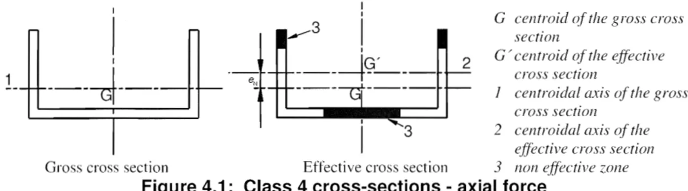
due to uniform axial compression. For non-symmetrical cross sections the possible shift eN of the centroid of the effective area Aeff relative to the centre of gravity of the gross cross-section, see Figure 4.1, gives all
additional moment which should be taken into account in the cross section verification using 4.6.
(4) The effective section modulus lVeff should be determined assuming the cross section is subject only to bending stresses, see Figure 4.2. For biaxial bending effective section moduli should be determined about both main axes.
NOTE: As an alternative to and (4) a single effective section may be determined from NEd and Ivhd acting
EN 1993-1-5:2006 (E)
(5) The stress in a tlange should be calculated using the elastic section modulus with reference to the mid-plane of the flange.
(6) Hybrid girders may have flange material with yield strength};!f up to fA1Xj~W provided that:
a) the increase of llange stresses caused by yielding of the web is taken into account by limiting the stresses in the web
b) .f~r ~ text deleted @l] is used in determining the effective area of the web.
NOTE: The National Annex may the value ~~1' A value of ~l
=
2,0 is recommcndcd.(7) The increase of deformations and of stresses at serviceability and fatigue Jimit states may be ignored for hybrid girders complying with 4.3(6) including the NOTE.
(8) For hybrid girders complying with 4.3(6) the stress range limit in EN 1993-1-9 may be taken as
1,5fyr.
1
---I I I I I---J---
..,...-3
I
IIG'
---t---
----U----I
3
2G centroid of the gross cross section
G / centroid (~i' the effective cross section
1 centroidal axis of the gross cross section
2 centroidal a:x:is qi'the ellective cross section Gross cross section Effective cross section
3
!lOll effective zoneFigure 4.1: Class 4 cross-sections - axial force
G
_·_-cr
!
!
---1---
IGI
I
-
1----"'1---G'I
I 1I
1 2 2-G centroid of the gross cross section
G' centroid of the effective cross section
1 centroidal axis qfthe gross cross section
2 centroidal axis qf the effective crcg,'S section Gross cross section Effective cross section
3
non effective zone4.4 Plate elements without longitudinal stiffeners
EN 1993-1-5:2006 (E)
(1) The effectiveP areas of flat compression elements should be obtained using Table 4.1 for internal elements and Table 4.2 for outstand elements. The effectiveP area of the compression zone of a plate with the
gross cross-sectional area At: should be obtained from:
=pAc
where p is the reduction factor for plate buckli ng. (2) The reduction factor p may be taken as follows:
internal compression elements:
p= 1,0
p
="2
p -0,
~~5
(3
+
¥/)
~
1,0
A;J
outstand compression elements:
p= 1,0
=
A
p -OJ
88<
1
°
P
-')
- ,
A;J
-whereAp
bIt
28,4£.Jk:
for ~p SO,5+~O.085-0.055\V @il for ~p >O,5+~O.085-0.055\V,
for
Ap
~ 0,748 forAp
>
0,748IfI is the stress ratio determined in accordance with 4.4(3) and 4.4(4)
-(4.1 )
lEi) text deleted @il (4.2)
(4.3)
b
is the appropriate width to be taken as follows (for definitions, see Table 5.2 of EN 1993-1 I)hw
for webs~h for internal flange elements (except RHS);
h -3 t for flanges of RHS;
c for outstand flanges;
h for equal-leg angles;
h for unequal-leg angles;
kcr is the buckling factor corresponding to the stress ratio IfI and boundary conditions. For long plates kcr is given in Table 4.1 or Table 4.2 as appropIiate;
is the thickness;
Ucr is the elastic critical plate buckling stress see equation (A.l) in Annex A.l (2) and Table 4.1 and Table
4.2;
235
£=
/i'
[N I
l111n2]
(3) For flange elements of I-sections and box girders the stress ratio 1jI used in Table 4.1 and Table 4.2
should be based on the properties of the gross cross-sectional area, due allowance being made for shear lag in the flanges if relevant. For web elements the stress ratio IfI used in Table 4. I should be obtained using a stress distribution based on the effective area of the compression flange and the gross area of the web.
NOTE: If the stress distribution results from different stages of construction (as e.g. in a composite bridge) the stresses from the various may first be calculated with a cross section consisting of effective flanges and
EN 1993-1-5:2006 (E)
gross web and these stresses are added together. This resulting stress distribution determines an effective web section that can be used for all stages to calculate the fi nal stress distribution for stress analysis.
(4) Except as given in 4.4(5), the plate slenderness
Ap
of an element may be replaced by:(4.4)
where O"colll.Ed is the maximum design compressive stress in the element determined using the effectiveP area of the section caused by all simultaneous actions.
NOTE 1: The above procedure is conservative and requires an iterative calculation in which the stress ratio I/f
(see Table 4.1 and Table 4.2) is determined at each step from the stresses calculated on the effectiveP cross-section defined at the end of the previous step.
NOTE 2: See also alternative procedure in Annex E.
(5) For the verification of the design buckling resistance of a class 4 member using 6.3.1, 6.3.2 or 6.3.4 of EN 1 993-1-1, either the plate slenderness or
A
p.red with (hom.Ed based on second order analysis with global imperfections should be used.(6) For aspect ratios alb
<
1 a column type of buckling may occur and the check should be performed according to 4.5.4 using the reduction factorPc.
NOTE: This applies e.g. for flat elements between transverse stiffeners where plate buckling could be column-like and require a reduction factor Pc close to Xc as for column buckling, see Figure 4.3 a) and b). For plates with longitudinal stiffeners column type buckling may also occur for alb ~ 1, see Figure 4.3 c).
a) column-like behaviour of plates without longitudinal SUPP011S
,/
/
/
//
/.
,// /
/ - '. J1//JI'/ k=71"--...,..<-.--L/'"
/ / / /
,,;;-/
/ // / / /
b) column-like behaviour of an unstiffened plate with a small aspect ratioa
column-like behaviour of a longitudina]]y stiffened plate with a large aspect ratio
a
EN 1993-1-5:2006 (E)
Table 4.1: Internal compression elements
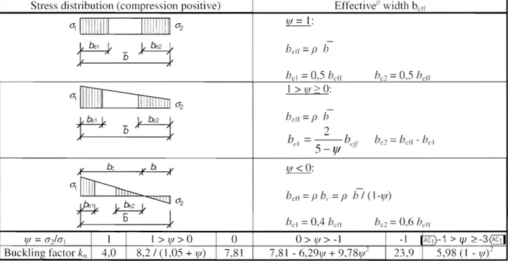
Stress distribution (compression positive) EffectiveP width b
eiT 01
III!!
iIIIII
lilll[[[111 a2r
E4
=pb
be
1 = 0,5 belT ] > Ijf> 0: a2 belT = P -1 > 1J1 2-3~Buckling factor I (1 ,05 + VI) 7,81 7,81 -6,29W + 9,78Vr 5,98 (I -Vlt
Table 4.2: Outstand compression elements
Stress distribution (compression positive) EffectiveP width b
eiT
bell = pc
°
-1Bucklina factor
k::;
0,43 0,57 0,85 0,57 - 0,21 VI +0,07VI-1
>
1jJ> 0:01
°
°
>
VI>-1EN 1993-1-5:2006 (E)
4.5
Stiffened plate elements with longitudinal stiffeners
4.5.1
General
(I) For plates with longitudinal stiffeners the effectiveP areas from local buckling of the various subpanels between the stiffeners and the effectiveP areas from the global buckling of the stiffened panel should be accounted for.
(2) The effectiveP section area of each subpanel should be determined by a reduction factor in accordance with 4.4 to account for local plate buckling. The stiffened plate with effectiveP section areas for the stiffeners should be checked for global plate buckling (by modelling it as an equivalent orthotropic plate) and a reduction factor IE1) Pc @ilshould be determined for overall plate buckling.
(3) The effectiveP area of the compression zone of the stiffened plate should be taken as:
(4.5) where is the effectivePlE1)section area@ilof all the stiffeners and subpane]s that are ful1y or partially in the compression zone except the effective parts supp0l1ed by an adjacent plate element with the width
see example in Figure 4.4.
(4) The area should be obtained from:
A.
c,c:I(Joc --
+
"P
L...J17{·.'I)I ..
ttoe
(4.6)
where
L
app1ies to the pat1 of the stiffened pane] width that is in compression except the parts see Figure 4.4;Asl.eff is the sum of the effectiveP sections according to 4.4 of all longitudinal stiffeners with gross area A~f located in the compression zone;
is the width of the compressed patt of each subpanel;
Pine is the reduction factor from 4.4(2) for each subpanel.
: 171 ,edge ,eff I I
~Ac
I hI PI Ac,eH,]oc2
h
3,edge,etTEN 1993-1-5:2006 (E)
(5) In determining the reduction factor Pc for overal1 buckling, the reduction factor for column-type buckling, which is more severe than the reduction factor than for plate buckling, should be considered.
(6) Interpolation should be carried out in accordance with 4.S.4( I) between the reduction factor p for plate buckling and the reduction factor Xc for column buckling to determine pc see 4.5.4.
(7) The reduction of the compressed area through Pc may be taken as a uniform reduction across
the whole cross section.
(8) If shear lag is relevant (see 3.3), the effective cross-sectional area of the compression zone of the stiffened plate should then be taken as accounting not only for local plate buckling effects but also for shear lag effects.
(9) The effective cross-sectional area of the tension zone of the stiffened plate should be taken as the gross area of the tension zone reduced for shear lag if relevant, see 3.3.
(10) The effective section modul us WelT shou ld be taken as the second moment of area of the effecti ve cross section divided by the distance from its centroid to the mid depth of the flange plate.
4.5.2 Plate type behaviour
(1) The relative plate slenderness
A
J> of the equivalent plate is defined as:AI'
=
(4.7)with
fJ
iLc = --'-'--joewhere
Ac
is the gross area of the compression zone of the stiffened plate except the parts of subpanelssupported by an adjacent plate, see Figure 4.4 (to be multipl ied by the shear lag factor if shear lag is relevant, see 3.3);
is the effective area of the same part of the plate (including shear lag effect, if relevant) with due allowance made for possible plate buckling of subpanels and/or stiffeners.
(2) The reduction factor p for the equivalent 011hotropic plate is obtained from 4.4(2) provided
A
p isca1culated from equation (4.7).
NOTE: For calculation of OCr.p see Annex A.
4.5.3 Column type buckling behaviour
(J) The elastic critical column buckling stress (1CLC of an unstiffened (see 4.4) or stiffened (see 4.5) plate should be taken as the buckling stress with the supports along the longitudinal edges removed.
(2) For an llnstiffened plate the elastic critical column buckling stress lkLC may be obtai ned from
Jr2
E
t
2(4.8)
(3) For a stiffened plate lkLC may be determined from the elastic critical column buckling stress lkr.sl of the
stiffener closest to the panel edge with the highest compressive stress as follows:
Jr2
E
(Jcr..;-f =
---.;...-AII,I a
EN 1993-1-5:2006 (E)
where IVI.1 is the second moment of area of the gross cross section of the stiffener and the adjacent parts
of the plate, relative to the out-of-plane bending of the plate;
is the gross cross-sectional area of the stiffener and the adjacent parts of the plate according to
A.1.
b.
NOTE: UCI.C may be obtained fronl 0" ." .
=
0",. ,{ - ( - , where lkr,c is related to the compressed edge of the( .( (,.1 l
platc, and, Figure A.I.
') 1'1,1
and be are geometric valucs from the stress distribution used for the extrapolation, see
(4) The re1ative column slenderness
Ac
is defined as foJ]ows:for unstiffened plates (4.1 0)
for stiffened plates (4.11 )
with
All.!
.I is defined in 4.5.3(3);
is the effecti ve cross-sectional area of the stiffener and the adjacent pat1S of the plate with
due allowance for plate buckling, see A.I.
(5) The reduction factor
Xc
should be obtained from 6.3.1.2 of EN 1993-1-1. For unstiffened plates a=
0,21 corresponding to buckling curve a should be used. For stiffened plates its value should be increased to:0,09
a =a+
Ci
Ie
(4.12) withe max , e2) is the distance from the respective centroids of the plating and the one-sided
stiffener (or of the centroids of either set of stiffeners when present on both sides) to the neutral axis of the effective column, see Figure A.I;
a = 0,34 (curve b) for closed section stiffeners;
=
0,49 (curve c) for open section stiffeners.4.5.4 Interaction between plate and column buckling
(I) The final reduction factor Pc should be obtained by interpolation between
Xc
andpas
fonows:(4.13)
Xc
is the reduction factor due to column buckling.p
is the reduction factor due to plate buckling, see 4.4( I).4.6 Verification
(1) Member verification@1)tor compression and uniaxial bending
'71
=
--=-=-Y,""0
EN 1993-1-5:2006 (E)
should be performed as follows:
(4.14)
where ActT is the effective cross-section area in accordance with 4.3(3);
eN is the shift in the position of neutral axis, see 4.3(3);
M
Ed is the design bending moment;is the design axial force;
Vl/eff is the effective elastic section modulus, see 4.3(4); /1v10 is the partial factor, see application parts EN 1993-2 to 6.
NOTE: For members subject to compression and biaxial bending the abovc equation (4.14) may be modified as follows:
+ N",d
e
z.NJI
W:::.e(l~
1,0
(4.15)Y,"'fO
Mz.Ed are the design bending moments with respect to y-y and z-z axes respecrively:
IEJ) ey.N, ez,N ~ are the eccentricities with respect to the neutral axis.
(2) Action effects MEd and should include global second order effects where relevant.
(3) The plate buckling verification of the panel should be carried out for the stress resultants at a distance O,4a or 0,5b, whichever is the smallest, from the panel end where the stresses are the greater. In this case the gross sectional resistance needs to be checked at the end of the panel.
5 Resistance to shear
5.1
Basis
(I) This section gives rules for shear resistance of plates considering shear buckling at the ultimate limit state where the following criteria are met:
a) the panels are rectangular within the angle limit stated in 2.3~
b) stiffeners, if any, are provided in the longitudinal or transverse direction or both;
c) all holes and cut outs are small 2.3);
d) members are of uniform cross section.
(2) Plates with hw1f greater than
72
E for an unstiffened web, or 31 for a stiffened web, should be'7
rychecked for resistance to shear buckling and should be provided with transverse stiffeners at the supports,
where E
=
235
EN 1993-1-5:2006 (E)
NOTE 1: h\\ see Figure 5.1 and for k, see 5.3(3).
NOTE 2: The National Annex will define 77. Thc value 77 == 1,20 is recommended for steel grades up to and including S460. For highcr steel grades '7 == J ,00 is recommended.
5.2 Design resistance
(I) For ullstiffened or stiffened webs the design resistance for shear should be taken as:
v
+
V.
<
17
f,,,-
!til
t
1M. Nil h./ J<d -
'3
-y j rMI
(5.1)
in which the contribution from the web is given by:
(5.2)
and the contribution from the flanges VbLRd is according to
5.4.
(2) Stiffeners should comply with the requirements in 9.3 and welds should fulfil the requirement given in
9.3.5.
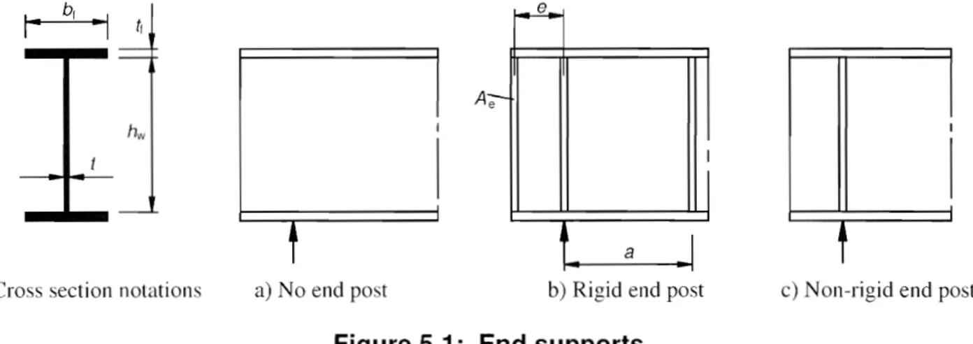
I
I
a
I
t
Cross section notations a) No end post b) Rigid end post c) Non-rigid end post
Figure 5.1: End supports
5.3 Contribution from the web
(I) For webs with transverse stiffeners at supports only and for webs with either intermediate transverse stiffeners or longitudinal stiffeners or both, the factor
Xw
for the contribution of the web to the shear buckling resistance should be obtained from Tab1e 5.1 or Figure 5.2.Table 5.1: Contribution from the web
XW
to shear buckling resistance
Rigid end post N on-rigid end post
AII'<0,83I17
'7
'7
-
-0,83117 SAil'
<
1,08
0,831
All'
0,831
1,37/(0,7
+
2\1')
-~
1,08
0,831
All'
EN 1993-1-5:2006 (E)
(2) Figure 5.] shows various end supp0l1s for girders:
a) No end post, see 6.1 (2), type
b) Rigid end posts, see 9.3.1; this case IS also applicable for panels at an intermediate support of a continuous girder;
c) Non rigid end posts see 9.3.2.
(3) The modified slenderness @il
;L
in Table 5.1 and 5.2 should be taken as:;L·
0,76
NOTE 1: Values for (IE and k, may be taken from Annex A.
NOTE 2: The ~ modified slenderness
a) transverse stiffeners at supports on ly:
may be taken as follows:
A.
H· =-86,4 t c
b) transverse stiffeners at supports and intermediate transverse or longitudinal stiffeners or both:
11\\
37,4
tc
Jk:
in which kT is the minimum shear buckling coefficientf~)I' the weh panel.
(5.3)
(5.4)
(5.5)
(5.6)
NOTE 3: Where non-rigid transverse stiffeners are also used in addition to rigid transverse sti ITeners, kr. is taken
as the minimum of the values from the web panels between any two transverse sti ffeners {/2 hw and (/Cl X
hw) and that between two rigid stiffeners containi ng transverse stiffeners (e.g. 0-1 X 11\\.).
NOTE 4: houndaries may he assumed for panels bordered by flanges and rigid transverse stiffeners. The web buckling analysis can then be based on the panels between two adjacent transverse stiffeners al X 111
Figure 5.3).
NOTE 5: For non-rigid transverse stiffeners the minimum value kr. may be obtained from the buckling analysis
of the following:
1. a combination of two adjacent web panels with one flexible transverse stiffener 2. a combination of three adjacent web panels with two flexihle transverse stiffeners For procedure to determine k;; see Annex A.3.
(4) The second moment of area of a longitudinal stiffener should be reduced to 1/3 of its actual val Lie when calculating kv Formulae for kr taking this reduction into account in A.3 may be used.
EN 1993-1-5:2006 (E)
1,3 { ,23·
1,;
0,9 0,8 0,7AW
0,6 0,5 0,4 0,3 0,2 0,1°
-" I I I i I i ! I ! r~\
I i'\
I " II'\.
i~,
Ii~
! I i i i , I I I I i I , t I i ! i i I I ! ! ! I I , I I r;- I I~
I
: !~V
: I i~l"
I"----
! I ... ~....
---
---r---l-(
-....
---
r--l-
[--2
1
i ---I ! ! I I I I I I I°
0,2 0,4 0,6 0,8 1,2 1,4 1,6 1,8 2 2,2 2,4 2,6 2,8 31 Rigid end post
2 Non-rigid end post
3 Range of recommended TJ
Figure 5.2: Shear buckling factor
Xw
(5) For webs with longitudinal stiffeners the ~ modified slenderness @il
All'
in (3) should not be taken as less than(5.7)
where hWi and k,i refer to the subpanel with the largest ~ modified slenderness @il
Au:
of all subpanelswithin the web panel under consideration.
NOTE: To calculate the expression given in A.3 may be used with kTSI = O.
(a)
1 Rigid transverse st(ffener 2 Longitudinal st{fiener
3 Non-rigid transverse stiffener
h w
B-B
EN 1993-1-5:2006 (E)
Figure 5.3: Web with transverse and longitudinal stiffeners
5.4 Contribution from flanges
(l) When the flange resistance is not completely utilized in resisting the bending moment (MLd
<
MI',ReI) the contribution from the tlanges should be obtained as fo]]ows:C YMI
[I
( M f:"d
12
l
Mr,Rd )
(5.8)
br and tr are taken for the t1ange which provides the least axial resistance,
hr
being taken as not larger than 15t:tr on each side of the web,Mr,l?d
is the moment of resistance of the cross section consisting of the effective area of the flanges only, c[
1,6,
bJ~
fl,'/"
J
a
025
+
" ,
,
t
I")
1\: .
f'
r\t(2) When an axial force NEd is present, the value of Nlf.ReI should be reduced by multiplying it by the following factor:
[I
(5.9)
whereAfl and An are the areas of the top and bottom flanges respectively.
5.5 Verification
(1) The verification should be pelformed as follows:
(5.10)
where is the design shear force including shear from torque.
6 Resistance to transverse forces
6.1
Basis
(l) The design resistance of the webs of rolled beams and welded girders should be determined 111 accordance with 6.2, provided that the compression tlange is adequately restrained in the lateral direction. (2) The load is applied as follows:
a) through the flange and resisted by shear forces in the web, see Figure 6.1 (a);
b) through one and transferred through the web directly to the other flange, see Figure 6.1 (b). c) through one flange adjacent to an unstiffened end, see Figure 6. I (c)
EN 1993-1-5:2006 (E)
(3) For box girders with inclined webs the resistance of both the web and flange should be checked. The internal forces to be taken into account are the components of the external load in the plane of the web and flange respectively.
(4) The interaction of the transverse force, bending moment and axial force should be verified Llsing 7.2.
Type (a) Type (b) Type (c)
f
12
r '
J
k
F6
+
2l~
I =3,5
+
2
=2
+
6
5\+
CS 6
a )
\
hH'
Figure 6.1: Buckling coefficients for different types of load application
6.2 Design resistance
(1) For unstiffened or stiffened webs the design resistance to local buckling under transverse forces should
be taken as
(6.1 )
where tw is the thickness of the web;
f~w is the yield strength of the web;
Lefr is the effective length for resistance to transverse forces, which should be determined from
where t~ is the effective loaded length, see 6.5, appropliate to the length of stiff bearing see 6.3; Xr: is the reduction factor due to local buckling, see 6.4( 1).
6.3 Length of stiff bearing
(I) The length of stiff bearing s, on the flange should be taken as the distance over which the applied load is effectively distributed at a slope of ]: 1, see Figure 6.2. However, s~ should not be taken as larger than I1w.
If severa] concentrated forces are closely spaced, the resistance should be checked for each individual force as well as for the total load with Ss as the centre-to-centre distance between the outer loads.
~~/
~;Y
~Fs
!Fs
~Fs
_____
~~~/~~~
_____
~I/~~
_____
~~,
___________
j~L~
__________
~I(~)~(~)1--t~
} ss}
W
W
tf Ss == 0EN 1993-1-5:2006 (E)
(3) If the bealing surface of the applied load rests at an angle to the flange surface, see Figure 6.2, s, should be taken as zero.6.4 Reduction factor %F for effective length for resistance
(I) The reduction factor %r should be obtained from:
(6.3)
where
AF
(6.4)(6.5)
(2) For webs without longitudinal stiffeners kr should be obtained from Figure 6.1.
NOTE: For webs with longitudinal stiffeners information may be given in the National Annex. The following rules are recommended:
For webs with longitudinal stiffeners kF may be taken as
kF
6
+
2
[':'J
+
[5,44
~
0,21].JY:"
(6.6)where bJ is the depth of the loaded subpanel taken as the clear distance between the loaded /lange and the
stiffener
y,
=10,9
~,:!;~ ~ 13l
:J
+
210[0,3 -
~]
where IIU is the second moment of area of the stiffener closest to the loaded /lange including contributing parts of the web according to Figure 9.1.
Equation (6.6) is valid for
0,05
~ ~0,3
and ~0,3
and loading according to type a) in Figure 6.1.a
hl\'
(3)
fy
should be obtained from 6.5.6.5 Effective loaded length
(l) The effective loaded length should be calculated as follows:
f
,r
b
r
111)=-"-'
if
>0,5
ifAF
~0,5
For box girders, bf in equation (6.8) should be limited to 15ctf on each side of the web.
(2) For types a) and b) in Figure 6.1,
ty
should be obtained using:e
y=
Ss+
2
tr
(1
+
,bute"
~ distance between adjacent transverse stiffeners(6.8)
(6.9)
EN 1993-1-5:2006 (E)
(3) For type c)
fy
should be taken as the smallest value obtained from the equations (6.1 ]) and (6.12).@il(6.11 )
(.1 = (e
+t,
(6.12)where @ilec (6.] 3)
6.6
Verification
(]) The verification should be performed as follows:
(6.14)
where is the design transverse force;
L
efe is the effective length for resistance to transverse forces, see 1ED6.2(1);tw is the thickness of the plate.
7 Interaction
7.1
Interaction between shear force, bending moment and axial force
(I) Provided that 773 (see below) does not exceed 0,5 , the design resistance to bending moment and axial force need not be reduced to allow for the shear force. If
773
is more than 0,5 the combined effects of bending and shear in the web of an lor box girder should satisfy:ry]
+
(1 -
M
(2173
1)'
~
],0
for
17,
~ ~
1.Hdpl.HI! pl,Ht!
(7.1)
where NhRd is the design plastic moment of resistance of the section consisting of the effective area of the flanges;
MpLRd is the design plastic resistance of the cross section consisting of the effective area of the flanges and the fully effective web irrespective of its section class.
M
c ,771
=
M
fpl.Nd
lED
for ~)\1.Rd see expression (5.2), @il In addition the requirements in sections 4.6 and 5.5 should be met.Action effects should include global second order effects of members where relevant.
EN 1993-1-5:2006
(E)
(3) The plastic moment of resistance MLRd may be taken as the product of the yield the effective
area of the flange with the smallest value of Arf/{f1'1O and the distance between the centroids of the flanges. (4) If an axial force is present, Mpl.Rd and NhRd should be reduced in accordance with 6.2.9 of
EN 1993-1-1 and 5.4(2) respectively. When the axial force is so large that the whole web is in compression 7.1 (5) should be applied.
(5) A llange in a box girder should be verified using 7. I (]) taking
°
and TEd taken as the averageshear stress in the flange which should not be less than half the maximum shear stress in the flange and 771 is taken as 171 according to 4.6( I). In addition the sllbpanels should be checked using the average shear stress within the subpanel and XW determined for shear buckling of the sllbpanel according to assuming the longitudinal stiffeners to be rigid.
7.2 Interaction between transverse force, bending moment and axial force
(1) If the girder is subjected to a concentrated transverse force acting on the compression flange in conjunction with bending and axial force, the resistance should be verified using 4.6, 6.6 and the following interaction expression:
772
+
0,8 771
~1,4
(7.2)(2) If the concentrated load is acting on the tension flange the resistance should be verified according to section 6. Additionally 6.2.1 (5) of EN 1993-1-1 ShOll Id be met.
8 Flange induced buckling
(1) To prevent the compression flange buckling in the plane of the web, the fol1owing criterion should be met:
where Aw is the cross section area of the web;
Arc is the effective cross section area of the compression flange;
hI\' is the depth of the web;
tw is the thickness of the web.
The value of the factor k should be taken as follows: plastic rotation utilized k
=
0,3 plastic moment resistance utilized k 0,4elastic moment resistance utilized k 0,55
(2) When the girder is curved in elevation, with the compression flange on the concave criterion should be met:
r is the radius of curvature of the compression
NOTE: The National Annex may further information on flange induced buckling.
(8.1 )
the following
EN 1993-1-5:2006 (E)
9 Stiffeners and detailing
9.1
General
(1) This section gives design rules for stiffeners in plated structures which supplement the plate buckling rules specified in sections 4 to 7.
NOTE: The National Annex may further requirements on stiffeners for specific applications.
When checking the buckling resistance, the section of a stiffener may be taken as the gross area comprising the stiffener plus a width of plate equal to 15et but not more than the actual dimension available, on each side of the stiffener avoiding any overlap of contributing parts to adjacent stiffeners, see Figure 9.1.
(3) The axial force in a transverse stiffener should be taken as the sum of the force resulting from shear (see 9.3.3(3» and any external loads.
~ij/~~
Figure 9.1: Effective cross-section of stiffener
9.2 Direct stresses
9.2.1 Minimum requirements for transverse stiffeners
(I)
In
order to provide a rigid support for a plate with or without longitudinal stiffeners, intermediate transverse stiffeners should satisfy the criteria given below.(2) The transverse stiffener should be treated as a simply supported member subject to lateral loading with
an initial sinusoidal imperfection tVa equal to s/300, where s is the smallest of ai, {/2 or b, see Figure 9.2 ,
where {/ I and Cl2 are the lengths of the panels adjacent to the transverse stiffener under consideration and b is
the height between the centroids of the flanges or span of the transverse stiffener. Eccentricities should be accounted for.
f
.n.f----
l
-b_----,.tJ
I Transverse stiffener
Figure 9.2: Transverse stiffener
EN 1993-1-5:2006 (E)
and axial force according to the NOTE to 9.3.3(3). The compressed panels and the longitudinal stiffeners are considered to be simply supported at the transverse stiffeners.
(4) It should be verified that using a second order elastic method analysis both the following criteria are satisfied at the ultimate limit state:
that the maximum stress in the stiffener should not exceed f/li.,;! I.
that the additional detlection should not exceed b/300.
(5) In the absence of an axial force in the transverse stiffener both the criteria in (4) above may be assumed to be satisfied provided that the second moment of area Is[ of the transverse stiffeners is not less than:
II"
(
1
+
Hlo300)
b
II(9.1 )
where 1(2£ U =300 b ;:::: 1,0
YMIemax is the maximum distance from the extreme fibre of the stiffener to the centroid of the stiffener; NEd is the maximum compressive force of the adjacent panels but not less than the maximum
compressive stress times half the effectiveP compression area of the panel including stiffeners;
(JCLC' are defined in 4.5.3 and Annex A.
NOTE: Where out of plane loading is applied to the transverse stiffeners reference should be 111ade to EN 1993-2 and EN 1993-1-7.
(6) If the stiffener carries axial compression this should be increased by
MIl
= (J'I)/ / in order to account for deviation forces. The criteria in (4) apply but ANq need not be considered when calculating theuniform stresses from axial load in the stiffener.
(7) As a simplification the requirement of (4) may, in the absence of axial forces, be verified using a first order elastic analysis taking account of the following additional equivalent uniformly distributed lateral load
q acting on the length b:
q
:
(J'III(l~'a
+
Wei)where 0;11 is defined in (5) above;
Wa is defined in Figure 9.2;
(9.2)
Wei is the elastic deformation, that may be either determined iteratively or be taken as the maximum
additional deflection 17/300.
(8) Unless a more advanced method of analysis is carried out in order to prevent torsional buckling of stiffeners with open cross-sections, the following criterion should be satisfied:
f,
E
where
Ip
is the polar second moment of area of the stiffener alone arollnd the edge fixed to the plate; IT is the St. Venant torsional constant for the stiffener alone.EN 1993-1-5:2006 (E)
(9) Where warping stiffness is considered stiffeners should either fulfil (8) or the criterion
(9.4)
where Ckr is the elastic critical stress for torsional buckling not considering rotational restraint from the plate;
B is a parameter to ensure class 3 behaviour.
NOTE: The parameter 8 may he given in the National Annex. The value 8= 6 is recommended.
9.2.2 Minimum requirements for longitudinal stiffeners
(l) The requirements concerning torsional buckling in 9.2.1(8) and (9) also apply to longitudinal
stiffeners.
(2) Discontinuous longitudinal stiffeners that do not pass through openings made in the transverse
stiffeners or are not connected to either side of the transverse stiffeners should be: used only for webs (i.e. not allowed in flanges);
neglected in global analysis;
neglected in the calculation of stresses;
considered in the calculation of the effectiveP widths of web sub-panels; considered in the calculation of the elastic critical stresses.
(3) Strength assessments for stiffeners should be performed according to 4.5.3 and 4.6.
9.2.3 Welded plates
(1) Plates with changes in plate thickness should be welded adjacent to the transverse stiffener, see Figure 9.3. The effects of eccentricity need not be taken into account unless the distance to the stiffener from the welded j unction exceeds bo/2 or 200 mm whichever is the smallest, where bo is the width of the p1ate
between longitudinal stiffeners.
)
\
I Transverse st~ffener
2
Transversevveld
Figure 9.3: Welded plates
\
(EN 1993-1-5:2006 (E)
9.2.4 Cut outs in stiffeners
(1) The dimensions of cut outs in longitudinal stiffeners should be as shown in Figure 9.4.
Figure 9.4: Cut outs in longitudinal stiffeners
(2) The lengthe
should not exceed:f
~6
tmin for flat stiffeners in compressionfor other stiffeners in compression
f
~15
tmin for stiffeners without compressionwhere 'min is the lesser of the plate thicknesses
(3) The limiting values
f
in (2) for stiffeners in compression may be increased by when(J\',E,d is the compression stress at the location of the cut-out
(4) The dimensions of cut outs in transverse stiffeners should be as shown in Figure 9,5.
(,,_/---~!
\\---r-U--r-r.r--.
-""'l'--~-o-,
6-h-s - - \
~·'~"-f·-\
\
/
/
~========================~i
'\
Figure 9.5: Cut outs in transverse stiffeners
(5) The gross web adjacent to the cut out should resist a shear force VEd , where
(9.5)
fnet is the second moment of area for the net section of the transverse stiffener;
e is the maximum distance from the underside of the flange plate to the neutral axis of net section, see Figure 9.5;