Appendix A.
Here a detailed description of the input impedances calculations is given.
A.1 Calculation of Zin for the Cascode with source degeneration inductor
Fig. A.1 exemplifies the complete small signal circuit of the Cascode with inductive degeneration, including the external Cb, Lg and the bias resistor.
b C Lg 1 gs C 1 gd C 1 1 gs mV g 1 o r 2 gs C bias R ZL 2 o r 2 2 gs mV g Ω 50 s L
Figure A.1 Complete variation circuit of the Cascode with LS
We can simplify this circuit by assuming that the impedance seen at the source of the common gate stage is about 1/gm 2 (Fig. A.2). At this point we can write a system of three equations where the
unknown quantities are the currents:
1 gs C 1 gd C 1 1 gs mV g 1 o r s L 2 / 1 gm P I I1 3 I I2 P V
Mesh A: ) ( ) ( 1 1 3 sL I I I I sC V P s P gs P = + + + (A.1) Mesh B: ) ( ) ( 1 1 0 3 I I3 r1 I1 I2 sC I sCgd + gs P + − o + = (A.2) Mesh C: ) ( ) ( 1 0 1 1 1 2 1 2 P s o m I I sL I I r I g + + + + = (A.3) Kirchhoff 1 at node K: ) ( 3 1 3 1 1 3 2 P gs m gs m I I sC g I V g I I =− − =− − + (A.4)
By replacing (A.4) in (A.2) and (A.3) the system can be written in matrix form:
− − + + − + + + − + + = 3 1 1 1 1 1 2 1 1 1 1 1 1 1 1 1 1 1 1 1 1 0 0 I I I sC r g r r g sL sC r g sL r sC r g sC r sC r g sC sL sL sC V P gs o m o o m s gs o m s o gs o m gd o gs o m gs s s gs P
that is in the form Y = M • X
From the Cramer theorem stems that:
P P I V 11 ∆ ∆ =
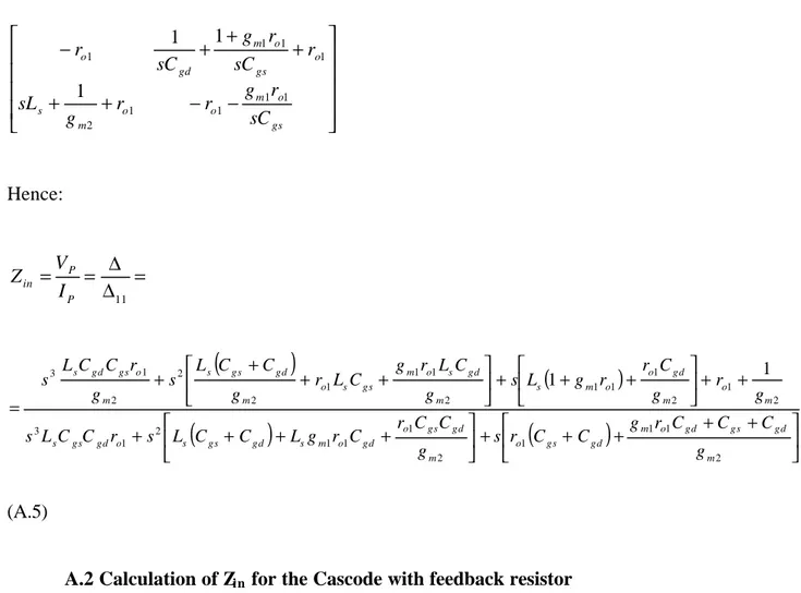
− − + + + + + − gs o m o o m s o gs o m gd o sC r g r r g sL r sC r g sC r 1 1 1 1 2 1 1 1 1 1 1 1 Hence: = ∆ ∆ = = 11 P P in I V Z
(
)
(
)
(
)
(
)
+ + + + + + + + + + + + + + + + + + = 2 1 1 1 2 1 1 1 2 1 3 2 1 2 1 1 1 2 1 1 1 2 2 2 1 3 1 1 m gd gs gd o m gd gs o m gd gs o gd o m s gd gs s o gd gs s m o m gd o o m s m gd s o m gs s o m gd gs s m o gs gd s g C C C r g C C r s g C C r C r g L C C L s r C C L s g r g C r r g L s g C L r g C L r g C C L s g r C C L s (A.5)A.2 Calculation of Zin for the Cascode with feedback resistor
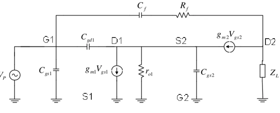
In Fig. A.3 is depicted the complete small signal circuit of the Cascode with feedback resistor:
Ω 50 b C Lg 1 gs C 1 gd C 1 1 gs mV g 1 o r 2 gs C bias R f C Rf L Z 2 o r 2 2 gs mV g
Figure A.3 Complete variation circuit of the Cascode with Rf
It includes the external Cb, Lg and the bias resistor. ZL is the LC-resonating load, where the
inductance includes its parasitic series resistance Rser. It reads:
1 2 + + + = load ser load load ser load L C sR C L s R sL Z (A.6)
At resonance its value coincides with RP, parallel equivalent resistance of the load. We neglect now
the output resistance of the CG MOS to simplify the calculation (Fig. A.4):
1 gs C 1 gd C 1 1 gs mV g 1 o r Cgs2 f C Rf L Z 2 2 gs m V g P V
Figure A.4 simplified variation circuit of the Cascode with Rf
Since the reactance of Cf is much smaller than Rf we neglect it as well. The parallel of ro1 and Cgs2
can be expressed in a more compact way with the impedance
1 1 2 1 1 = + o gs o r sC r Z (A.7)
Moreover, since Cgs is in parallel with the probe generator VP we can make all the calculations
without it and simply add it at the end. Vgs2 is equal to –Vs2 because the gate of the MOSFET 2 is
grounded. The current generator was consequently inverted.
We can write now two equations at the meshes A and B (Fig. A.5).
1 gd C 1 1 gs mV g 1 Z f R L Z 2 2 s m V g P V P I 1 I OUT V
Mesh A: ) ( ) ( 1 2 2 1 1 1 1 1 s m P m P P gd P I I Z I I g V g V sC V = + + + − − (A.8) where 1 1 2 1 1 1 2 2 1 1 2 1 ) ( Z Z g V g I I Z V g V g I I V m P m P s m P m P s + − + = − − + = (A.9)
Replacing Vs2 in A.8 we obtain
P m m gd m m m m P V Z g Z g Z sC Z g Z g g Z g I I 1 2 2 1 2 1 1 1 2 2 1 2 1 1 1 1 1 1 1 1 + − + + − + + − = (A.10) Mesh B: ) ( ) ( 1 ) ( 0 1 1 1 1 2 2 1 1 2 2 1 P P m P m s gd f s m L I I Z I I g V g V sC I R V g I Z − + + + + + − − = (A.11) replacing Vs2 (A.9) + − + − − + + + + + + − + − = 1 2 1 1 1 2 1 1 1 1 1 1 1 2 1 1 1 2 1 1 ) ( 1 1 g Z V g I I Z g V g I I Z I I sC I R Z g V g I I Z g I Z m P m P m P m P P gd f m P m P m L (A.12) replacing I1 (A.10) ...
1 1 1 2 1 1 2 1 1 2 2 1 2 1 1 1 2 2 1 2 1 1 1 1 1 1 2 1 1 2 * 1 ) ( 1 1 1 1 1 1 ) ( Z g Z g Z Z Z g g Z g Z g Z sC Z g Z g g Z g Z sC R Z g Z Z Z g Z R Z I V Z m m L m m m m gd m m m m gd f m L m L f L P P in − + + + + − + + − + + + + + + − + = = (A.13) 1 * 1 // gs in in sC Z Z = (A.14)