2.
STATE OF THE ART OF MICRO-MILLING TECHNOLOGY
2.1
Micro-machining technologies
The miniaturization of machine components is perceived by many as a requirement for the future technological development of a broad spectrum of products. The miniaturization of devices (Fig. 2.1) is today demanding the production of mechanical components with manufactured features in the range of a few millimeters to a few microns in fields that include aerospace, optics, electronics, medicine, biotechnology, communications, etc [13].
Micro-components (Fig. 2.2) fabrication requires reliable and repeatable methods with accurate analysis tools. Many common methods of manufacturing miniature components have been based on semi-conductor processing techniques (LIGA), where silicon materials are photo-etched through chemical and dry processes, usually in large batch production [43]. Micro-mechanical machining, such as Micro-electro discharge, Laser, Ion beam and Ultrasonic, is another means of fabrication method for creating miniature devices [2].
Recently there has been strong interest in fabricating micro/meso-scale components through mechanical cutting processes. Even though the mechanical micro-machining process may not be capable of obtaining the smallest feature sizes using with lithographic processes, mechanical cutting processes are very important in bridging the macro-domain and the nano- and micro-domains for making functional components [28] (.Fig. 2.3).
Fig. 2.1- Examples of micro-products[54]
Fig. 2.3- Dimensional size for the micro-mechanical machining [28]
2.1.1 Difference between micro-cutting and other methods
On one side comparing the micro-cutting with the other methods some advantages can be noticed. First of all micro-cutting process allows the use of a large variety of materials, while lithography processes are limited to a few silicon-based materials. Secondly micro-cutting has the capability of fabricating 3D free-form surface, while the others are limited to planar geometries. Thirdly the micro-cutting process has the ability to monitor the in-process quality of the components so that problems can be corrected during fabrication. Finally micro-cutting is cost-effective and does not require expensive set-ups, instead other methods have a high heat impact on the work-piece and need expensive set-ups [28].
On the other side micro-cutting process presents some disadvantages. It is unable to obtain the smallest feature sizes, which are proper of the LIGA process, with low surface roughness. Micro-cutting has a limited depth of cut and shows difficulties in the chip-disposal. Moreover it is influenced by the vibrations generated by the machine during the process. Other methods’ advantages regard the suitability for high-volume low-cost production and the availability of a large know-how of the processes [45].
2.1.2 Micro-machine and micro-factories
Since micro-structures are very small, several researchers and companies are trying to scale down the machine tools necessary to produce micro-components. Micro-machine tools do not necessarily have to be large to achieve the required precision and several benefits from this miniaturization include reduction in energy, space, materials and cost.
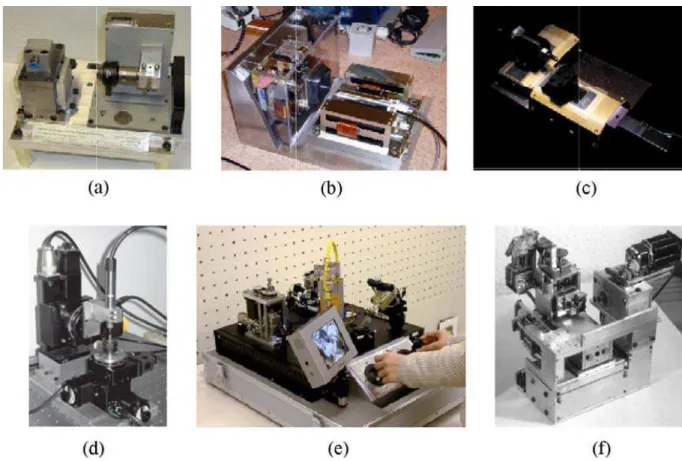
Micro-machine tools, shown in Fig. 2.4, are cost-effective in comparison with ultra-precision machine tools and require smaller amounts of materials to be fabricated. Therefore, machining centres can be constructed with more expensive materials that exhibit better engineering properties[45].
The portability of such systems is beneficial. Miniature machines introduced the new concept of small footprint factories known as micro-factories. For example, the small size of the machines allows for their deployment to any building or site. Micro-factories may be suitable for the production of micro-components during military or space exploration applications, since the accessibility of large machine tools is very difficult. Miniature factories can also have significant energy savings since the energy requirements are lower.
There are challenges associated with the development of micro-machine tools. They require accurate sensors and actuators, which must be small enough to implant within the machines. The structural rigidity of micro-machine tools is less than those of precision machines. In addition, the micro-machine tools can be excited by external disturbances; therefore, micro-factories require vibration isolation to achieve desired tolerances.
Fig. 2.4 - Micro-machines: (a) micro-factory; (b) 2nd generation miniature machine; (c) commercial miniature machine; (d) miniature machine; (e) micro-factory; (f) micro-machine tool
[28]
The accuracy and small features of micro-components are dependent on the machine tools that produce them. Conventional ultra-precision machine tools can produce the desired tolerances; however, in order to produce micro-components cost effectively, the reduced cost potential of micro-factories holds a promising future for research. Further studies are needed to improve the rigidity of micro-factories.
2.2
Micro-milling
2.2.1 Introduction
Among the micro-mechanical manufactory technologies, the micro-milling is one of the most potential for the production of miniaturized parts that may allow rapid and economic fabrication of meso-scale components with micro-scale features. It is a very flexible machining process for creating 3D free-form surfaces from a variety of engineering materials. Presently researchers are analyzing the potential of micro-milling technology for fabricating steel micro-moulds for injection moulding [24].
Micro-milling can be defined as a traditional milling process that has been scaled down to micron level. However due to the small diameter tools used in the process, micro-milling shows significant differences as compared with the conventional milling.
There are several phenomena in micro-milling that prevent the results of conventional milling from being applied to it directly. It is suitable to consider the three basic differences that arise from the drastic reduction in size:
• it cannot be assumed that the micro-structure of the work-piece material is homogeneous; as tool size is becoming smaller, its effect becomes more important;
• the effect of the cutting edge radius is not negligible: it affects the chip formation. Minimum chip thickness is a function of this parameter and determines the transition between two cutting conditions, where chips are produced and where ploughing takes place;
• as a result of high tool conformation and the relative size of the cutting edge radius the associated dynamic effects, i.e. forced vibration and regenerative chatter, differ from conventional milling with regard to stability conditions.
The most aspects of micro-milling are discussed below.
2.2.2 Rounded-Edge Cutting Model (RECM)
In micro-milling, as the depth of cut becomes of the same order as the tool edge-radius the assumption that the tool edge is perfectly sharp (Merchant's Sharp-Edge Cutting Model) is no longer valid and micro-machining may involve significant sliding along the clearance face of the tool due to the elastic recovery of the work-piece material [30].
It is necessary to introduce an orthogonal cutting model, the so-called Rounded-Edge Cutting Model (RECM), considering the cutting edge radius and the elastic recovery and then quantify these two effects, i.e. ploughing along the rounded edge and sliding on the clearance face.
Both this model and the Merchant's one are showed in Fig. 2.5.
2.2.3 Chip formation and minimum chip thickness
Chip formation is a dynamic process that is often nonlinear in nature. Understanding micro-chip formation is important in an accurate prediction of cutting forces. Since a chip may not form when the depth of cut is less than a minimum chip thickness, finding the minimum chip thickness has received much attention.
In macro-machining, the feed per tooth (i.e. depth of cut) is generally deeper than the cutting tool edge radius, but in micro-milling machining the cutting edge tool radius is in the same order of the depth of cut and that, as demonstrated in [27], causes the elastic-deformation of the work-piece during the process. It has been demonstrated [28] that in micro-milling machining chip may not form when the depth of cut is less than a minimum chip thickness: when the uncut chip thickness h is less than a critical minimum chip thickness hm, as shown in Fig. 2.6 (a), elastic deformation occurs and the cutter does not remove any work piece material; as the uncut chip thickness approaches the minimum chip thickness, chips are formed by shearing of the work piece, with some elastic deformation still occurring, as illustrated in Fig. 2.6(b); as a result, the removed depth of the work piece is less than the desired depth. However, when the uncut chip thickness increases beyond the minimum chip thickness, the elastic deformation phenomena decreases significantly and the entire depth of cut is removed as a chip, as shown in Fig. 2.6 (c).
Fig. 2.5- SECM and RECM [28] t rake angle -workpi ece workp rake
Fig. 2.6-Schematic of the effect of the minimum chip thickness [31]
The relationship between the tool radius and minimum chip thickness depends on the cutting edge radius and the material of the work-piece. It is very difficult to directly measure the minimum chip thickness during the process, in spite of knowing the tool edge radius. Researchers have estimated the minimum chip thickness either through finite element (FE) or experimental predictions.
2.2.4 Cutting force
The cutting force is directly related to chip formation.
The cutting force also determines the tool deflection and bending stress that limits the feedrate [31]. Well developed analytical cutting force models help operators choose the right cutting conditions for their system. There are two components to cutting forces namely, shearing and ploughing forces. Since the chip thickness in micro-milling applications can be comparable in size to the edge radius of the tool, the conventional sharp-edged theorem cannot be applied in micro-milling operations due to their large negative rake angle. In addition, the elastic-plastic deformation of the work piece also changes the cutting forces in micro-milling operations.
Kim et al. [30] showed analytically the differences in cutting forces between macro-milling and micro-milling processes. In the macro-model, shear takes place along a shear plane; whereas in micro-milling, the shear stress rises continuously around the cutting edge.
Liu et al. [27] found that the forced vibration of the tool and the elastic recovery of the work-piece contribute to the magnitude of the cutting force at low feedrates. They proposed the micro-end milling process as having three types of mechanisms: only elastic deformation (the uncut chip thickness is smaller than the minimum chip thickness), elastic and shearing deformation and shearing deformation (the uncut chip thickness is greater than the minimum chip thickness).
In micro-milling, the depth of cut is often less than the critical minimum chip thickness to avoid tool breakage and to maintain desired tolerances. This causes a large negative rake angle between the tool and work piece. Conventional sharp-edge macro-cutting models cannot be used to predict cutting forces in micro-milling applications. In addition, the work-piece material’s elastic-plastic effects and the static deflection of the tool cannot be discounted in micro-cutting force analysis.
2.2.5 Effect of work-piece material
Another significant challenge for micro-milling is tool/work-piece interactions.
In micro-milling, the nature of the work-piece must be considered in order to fabricate accurate micro-parts, as the depth of cut is sometimes less than the grain size in the work- piece material. The assumption of homogeneity in work-piece material properties is no longer valid, because micro-grain-structure size is often of the same order of magnitude as the cutter radius of curvature. This is a distinct difference between micro- and macro-milling, in fact the assumption in the latter is always that the materials are isotropic and homogenous [45].
It has been found that the changing crystallography and grain orientation during the cutting process affects shear angle and strength, causes variation in the micro-cutting force and generates vibration. This vibration is difficult to eliminate by changing the machine tool design or process conditions, because it originates from the work-piece.
The work-piece in micro-milling should be regarded as a non-homogenous material since the grain size is comparable to chip size. If possible, treatment of the work-piece should be considered to provide uniform micro-structural properties, allowing for better cutting force prediction [34].
2.2.6 Dynamics effects
Chaotic dynamic cutting processes, such as chatter, pose a significant problem in micro-milling because they result in excessive vibration that can lead to catastrophic failure. Chatter is an unstable, self-excited vibration that occurs as a result of an interaction between the dynamics of the machine tool and the work-piece. In traditional regenerative chatter stability, the occurrence of chatter is dependent on three factors: cutting conditions, work-piece material properties and the dynamics of the machine tool spindle system .
An accurate prediction of the structural dynamics of the machine tool system is critical to preventing chatter. However, experimental measurement of the dynamics of the machine tool structure at the tool tip is not feasible for micro-tools. Due to micro-tool size and fragility, impact hammer force tests cannot be applied to measure tool tip vibration. Often, micro-tools are modelled as cantilever beams. However, this may not correctly represent the dynamics at the tool tip [45].
High-speed machines also present new challenges for micro-milling. At higher speeds the dynamics of machine tools change, with an unbalanced spindle producing centrifugal and gyroscopic effects. Modelling and analysis of high-speed spindle dynamics with various bearing configurations and thermal expansions are important.
Instability in micro-milling is a very challenging problem due to various non-linear effects and time-variant dynamics. In particular, the feed rates of micro-milling operations can significantly affect the stability due to elastic deformation.
2.3
Requirements of micro-milling on machine tools
Before identifying the requirements of the micro-milling process on the machine tools, it is necessary to illustrate the meaning of some important words that will be used in the rest of the report.
• Accuracy: could be defined as the degree of agreement or conformance of a feature of the machine with the required dimensional and geometrical accuracy [26];
• Geometric errors: are those errors that are extant in a machine on account of its basic design, the inaccuracies built-in during assembly and as a results of the components used on the machine. These errors have different components like linear displacement error (positioning accuracy), straightness and flatness of movement of the axis, spindle inclination angle, squarness angle etc. [48]. They are responsible of the positional accuracy of the machine-tool.
• Dynamic errors: are concerned with the relative motion errors of several moving machine components that need to move in accordance with precise functional requirements [26].
Size and quality of micro-products depend on the properties of the machine tools used to produce them, including overall their accuracy and dynamic performance. Capabilities and quality
of the machine tools are vital to such product requirements as size, geometrical and positional accuracy, surface roughness and dimensional repeatability.
Thus, using the macro-scale knowledge and enriching with the micro-scale one, the analysis of the micro-milling requirements on machine tools has been developed.
It is assumed to be important in analysing a micro-milling machining before all to know the machine itself. In [28] are identify three main systems for a precision machine tools: the spindle, a precision stage and a controller. On each of them some requirements are listed:
• requirements on the spindle: a very high rotational speed is required to maintain acceptable the productivity and to take benefit from high speed machine because of the small radius; in fact on equal terms of feedrate the spindle speed should increase as the tool radius decreases (equation 2.1)
[
]
[
]
e cut mm nrev R V /min 60 2 min / =π
(2.1) where: Vcut is the feedrate,n is the spindle speed, Re is the tool radius.
For example to reach a common cutting speed of 2m/min using a micro-end milling of 100µm diameter, it is required a rotational speed spindle of 200.000rpm.
When the torque requirements are high, electric motors with hybrid-angular contact bearings are used. That limits the maximum speed to approximately 60.000rpm, since friction in the contact bearing results in the thermal expansion of the spindle. When a higher spindle speed is required, air bearing spindles with air turbines are typically used, but they produce very low torque. Air bearing spindles that exceed 200.000rpm are commercially available. Often to achieve higher speeds, ultra-precision machine tools are retrofitted with high-speed spindles that fit in the conventional tool holder interfaces.
• requirements on the stage: the low strength of the miniaturized end mills implies reduction and accurate control of the chip load, which requires high positional accuracy. An ultra-precision stage (i.e. XY table) is necessary to achieve high accuracies when fabricating micro-structures. It is requested also that the stage reaches quickly the required feedrate, so a large acceleration magnitude is required to allow that. Linear drive motors and a control system are commonly used in ultra-precision machine tools. Compared to conventional drive mechanisms such as ball screws, linear motors have no accumulative errors from friction and the motor-coupling, no loss of accuracy due to wear, and no backlash. They can also provide very high accelerations. The typical accuracy for ultra-precision machine tools using linear drive systems is ± 1µm.
A high rigidity is also required on the stage (see Chapter 5). Unlike macro-machine tools, the small size of the micro-machines implies a low stiffness of the single parts and the whole structure, because of the mass and geometry reduction. That causes displacements of the machine’s parts during the machining compromising the accuracy of the products. Finally a high damping is necessary to contrast the effects of the vibrations generated during the process. Even that may compromise the products accuracy.
• requirements on the controller: it is required the actuation of precisely based on precision sensors and actuators. However, the large scale and precisely controlled machining environment may add very high costs for the fabrication of miniature components. Examples of commercially available precision micro-machining centres are shown in Fig. 2.7
Fig. 2.7Examples of precision micro-machining centres [28]
Making a list of the main requirements of the micro-milling technology on machine tools, it is possible to identify, besides the ones just listed:
• High stiffness and damping: it is necessary to point out the importance of machine’ stiffness in controlling dimensional accuracy and surface finish of parts. Low stiffness, in fact, affects the level of vibration and chatters in tools and machines. If uncontrolled, vibration and chatter can resulting in the following factors:
o poor surface finish;
o loss of dimensional accuracy of the work piece; o loss of positional accuracy of the machine-tool;
o premature wear, chipping and failure of the cutting tool, which is crucial with brittle tool materials, such as tungsten carbide;
o damage to machine tools components from excessive vibrations; o objectionable noise generated, particularly if it is of high frequency.
• compensation for thermal expansion: in order to maintain an optimum cutting speed, the reduction of mill diameters requires machine tools with high rotational speed capabilities. A solution to update existing machine tools is the use of high speed attached spindles. Major
cooling, which prevent the achievement of a steady state. Moreover the difference in temperature between the cutting fluid and the machine tool frame is responsible for a temperature variation of the machine frame, with consequent variation of the relative position between tool and work-piece. It is necessary to control the expansion of the machine’s components in order to guarantee the requested accuracy during the process; • low run-out from spindle bearing and tool-holder: a small run-out from the spindle bearing
and the tool-holder is necessary to limit the breakage of the tool, because with a big run-out the cutting process is not balanced and the tool is overloaded on one cutting edge more than the other;
• foundation: it appears important the foundation’s mass and how it is installed in a plant. It is appropriate to use a granite foundation because it presents high stiffness, thermal stability, resistance to environment degradation and good damping capacity.
2.4
Current methods to evaluate machine tools
In order to verify that the requirements of the micro-milling technology on the machine tool have been satisfied it is necessary to find some methods to evaluate the performance of the machine tool. The micro-machining technology is a technology of new generation, so it is difficult to find in literature methods to evaluate the performance of micro-machine tool. Therefore a study of the existing performance evaluation methods for the macro-scale machine tools has been done.
Existing performance evaluation methods for macro-scale machine tools include [20]: • evaluation of the stiffness of the machine tool‘s components;
• studying of the dynamic effects; • measuring of the positional accuracy; • studying of the thermal aspects.
Subsequently it will be given a synthesis of the main performance evaluation methods found in literature.
2.4.1 Evaluation of the stiffness of the machine’s components
It is considered important in the literature to measure the stiffness of the machine tool. Frequently the evaluation methods plan the breakdown of the machine as a chain of components and the measurement of these components’ stiffness. Generally the machine is decomposed in: tool, tool-holder, spindle and the machine itself (including stages and foundation), thus those methods plan to measure the displacement of each component in the point where the force is applied and calculate the stiffness with the applied force to obtained deflection ratio.
The method explained in [13] schedules to determine the stiffness chain (machine + spindle + tool-holder + tool) with the application of a known load and the measurement of the ensuing deflection. Each element in the system is measured independently with specific and specially designed measuring methods used in each different case. At the end of the evaluation, in order to estimate the total stiffness of the chain, the real system has been transformed into a system that behaves in an equivalent way, as shown in Fig. 2.8.
This method uses a pulley mechanism to apply the load through calibrated weights and an optical camera to measure the deflection, as displayed in Fig. 2.9. The experiments confirm that the tool-holder stiffness can vary considerable if experiments are not performed correctly, and that as the tool diameter increases other elements must be considered, especially the tool-holder.
Fig. 2.8-Breakdown of stiffness into its component elements (left) and the equivalent layout (right) [13]
Fig. 2.9-Layout of tool stiffness test (left) and view of the tool and focus with 650X magnification camera [13]
The method illustrated in [35] indeed plans to determine the stiffness chain in a different way. The tool is fixed in the tool-holder shank, the displacement measuring (inductive or capacitance) sensors are installed and the machine is proceeded to be pushed by a force measuring Kistler dynamometric plate, as shown in Fig. 2.10.
Once the contact between the Kistler and the tool has been established, a displacement is applied at a constant very low speed to the machine’s linear axis. Meanwhile the displacement at the sensor is measured at the same time as the force caused by the displacement of the dynamometer. Also in this method, at the end of the evaluation, in order to estimate the total stiffness of the chain, the real system has been transformed into a system that behaves in an equivalent way. It results that in case of very slender tools the tool itself may be the most flexible link of the system, but even the influence of the rest of the system is very important to evaluate the stiffness of the machine tool.
From the literature regarding the stiffness evaluation methods, it is known that given the magnitude of inertial and cutting forces applied to the machine’ structure, the stiffness of the machine needs to be improved in the future to achieve the micro-machine tools’ accuracy goals.
2.4.2 Dynamic effects
In the literature it is widespread to watch out for the dynamic effects present during the machining process. Those cause many errors, some of which may affect the tool position, in both radial and feed directions, and the following error of the stages.
In [36], for instance, an optimal control strategy for isolating the vibrations of a machine tool structure in two directions (radial and feed) from the cutting tool in machining operations is applied.
Fig. 2.10-Deflection tests on the machine (tool, system, sensor and force application) and a ball-end mill of 8mm [14]
It has been assumed that maintaining a constant relative position between the cutting tool and the work-piece improves both surface quality and geometrical accuracy of the machined surface. The dynamic model for the machining process uses two identical Tefenol-D magnetostrictive transduced actuators, placed in orthogonal directions (radial and feed), to apply forces on the cutting tool. The actuators transform input currents from a digital estimator into forces needed to manipulate the cutting tool position. Fig. 2.11 shows the dynamic model of the machine tool structure.
Effectiveness of the control process is presented in terms of its effects on the tool’s acceleration in both radial and feed directions before and after the application of the control. That will reflect the effects of the machine tool’s vibrations on the tool. The whole dynamic model is described in a Laplace domain and a Kalman estimator-based simulink active control model simulates the machining process.
Another error that is related with the dynamic behaviour of the machine is the following error, as described in [20] that proposes an acceleration-based performance evaluation methodology. That is based on moves during which an individual stage undergoes constant acceleration from a stop up to the feed velocity appropriate for that acceleration; the acceleration then changes sign and the stage returns to zero velocity. During each move the following error (the difference between the CNC controller command position and the feedback encoder actual position reading) is recorded and the data are analyzed to determine the peak and RMS following error values.
A calculation of the relative accuracy as a function of the acceleration can be performed based on evaluating the following error associated with an acceleration magnitude, determining the corresponding tool size and calculating a relative accuracy between that following error and a feature size appropriate for the tool size.
Given a feature size and a desired relative accuracy, the mMT design requirements can be determinated based on calculating the required bandwidth. To achieve the requested bandwidth a combination of reduced motor inductance, increased operating voltage, increased motor peak force and/or reduced stage moving mass must be implemented.
2.4.3 Positional accuracy
The positional accuracy is the main performance that is evaluated. In the literature several articles handle the analysis of this performance. Some of them focus on modeling the geometric errors, in order to find a method to compensate them in an analytical way.
Those are based on mathematical knowledge and plan to obtain deterministic and stochastical values of the geometric errors, as described in [1] and [37]. The first describes a numeral-analytical accuracy calculation approach based on machined surfaces that are modelled by a form-shaping function while the machine tool is modelled as a chain of links. This method plans to evaluate squareness, linearity and parallelism of the machined part and predicts the error sources from the results of measurements of the machined work-piece on the machine tool. The second mentioned method counts on using a laser interferometer to measure three linear errors and three angular errors for each axis. Those are then analysed with a rigid body kinematics model considering the deterministic and the stochastical values of each error.
In many articles it has been found the identification of the 21 components of the geometric errors [7, 8], i.e. 18 errors (six errors for each axis, namely linear error, straightness, roll, pitch, yaw and squareness) in addition to three squareness errors. These methodologies plan to measure the errors with the laser interferometer that is the most widely used instrument for the machine tool calibration because of its accuracy. The disadvantage is that for the measurement of different types of error different optics are required.
In [10] and [12] J.H. Lee et al. develop a multi-DOF (Degree of freedom) system to measure five geometric error components simultaneously on each axis of an mMT. That plans a fixture, five capacitance sensors and a steel target with a high surface finish, as shown in Fig. 2.12.
This method may be implemented cost-effectively without high cost accessories as optics in the laser interferometer. Since that is easy to set up it can be used easily for assessment, calibration and compensation of miniaturized systems including miniaturized machine tools.
Twenty-one geometric errors can be measured also with a circular test, as described in [16] where the machine is programmed to move on a circle and the deviations from an ideal circle are measured, as shown in Fig. 2.13
Fig. 2.13-Response of the Circular Test to axial movement (scale error, 5 µm/m; diameter of nominal path, 500mm; maximum deviation from nominal diameter, 2.5µm) [16]
The test requires a master-piece in the form of a cylinder whose about 6 points are measured. It allows an on-line testing and is a quick method to test the accuracy; in fact a complete test takes about three hours.
The ISO-230 [25] indicates several methods to measure straightness, flatness and squareness. As regards the straightness, for instance, it proposes the laser interferometer technique, the tout-wire and microscope method and the alignment telescope method.
The method described in [17] looks at the machine’s accuracy as given by surface finishing and geometric accuracy and consists of manufacturing three ISO test-pieces, shown in Fig. 2.14, in three different materials on three different machines.
This method is useful in making a comparison between different machines, but it can not be used to evaluate a single machine. The disadvantage is that it requires a machined part.
2.4.4 Thermal aspects
In a micro-milling machining the influence of thermal factors is not negligible. During the process indeed heat is generated and the component is subjected to temperature variations. However all the found methods are addressed to macro-machine tools.
As Ramesh et al. report in [3] and [6] a continuous usage of machine tool causes heat generation at the moving elements and that causes expansion of the various structural elements of the machine itself. The thermal error in machine tools has been observed to be closely linked to the temperature of critical elements of the machine. These researches plan experiments made with thermocouples positioned in areas where there is the maximum likelihood of obtaining a measurable change in temperature rise on account of subjecting the machine to the different thermal cycles. The thermocouples are used together with laser interferometer or non contact capacitance sensors. The tests made evidence the important point that the thermal error of a machine tool is strongly dependent upon the specific operating parameters.
Thermal aspects cause also linear expansion of tool, spindle and supposable columns of the machine and that leads to error on the axial depth of cut. Based on the consideration that for repeatable working conditions the same temperature profile is generated, a calibration of the thermal elongation of the spindle has been carried out for selected rotational speed in [24].
Even for the analysis of the thermal aspects the ISO 230 mentioned for the positioning accuracy gives a guideline. The norm [22] indeed defines three different tests: the first to reveal the effects of the environmental changes on the machine and to estimate the thermally induced errors during other performance measurements; the second to identify the effect to internal heat generated by rotation of the spindle and the resultant temperature gradient along the structure on the distortion of the machine structure observed between the work-piece and the tool; the third to identify the effect of internal heat generated by the machine positioning system on the distortion of the machine structure observed between the work-piece and the tool in the direction of travel.
Other methods, as the one described in [23] propose a measurement of the change of length of a TDBB (Telescopic Double Ball Bar) at multiple locations in the machine’s working volume while the machine is thermally excited (Fig. 2.15). The machine’s thermal behaviour can be determined throughout its working volume by comparing measured TDBB lengths performed at successive time intervals corresponding to a certain location in the machine's workspace to those measured lengths determined when starting a measurement. The TDBB length measurements can be executed in few minutes due to the high measuring speed of a TDBB. This method measures and models the thermally induced positioning errors of multi-axis machines that result from changes in temperature distribution of such a machine.
2.5
Conclusions
From the literature survey (see Appendix F) it is possible to conclude that:
• about the static stiffness analysis the most used method is based on the modelling the machine’s components as a chain of elastic elements;
• for the dynamic effects, the method that involves the acceleration parameter is the most suitable to the micro-milling set-up;
• about the positional accuracy the laser interferometer, with the measure of the 21 error components, is the most used method;
• for the thermal expansion no method has been found regarding the micro-machine tools, so it is necessary to fit a conventional method to the micro-scale.
Given the knowledge form the literature survey an error budget of the setup has been draft and some methods among those studied are adapted to the machine in order to study its main performances.
![Fig. 2.2-Example of micro-machined features and parts [52]](https://thumb-eu.123doks.com/thumbv2/123dokorg/7272278.83505/1.892.151.746.915.1091/fig-example-micro-machined-features-parts.webp)
![Fig. 2.3- Dimensional size for the micro-mechanical machining [28]](https://thumb-eu.123doks.com/thumbv2/123dokorg/7272278.83505/2.892.243.652.83.334/fig-dimensional-size-micro-mechanical-machining.webp)
![Fig. 2.5- SECM and RECM [28] trake angle -workpieceworkprake](https://thumb-eu.123doks.com/thumbv2/123dokorg/7272278.83505/4.892.282.630.907.1081/fig-secm-recm-trake-angle-workpieceworkprake.webp)
![Fig. 2.6-Schematic of the effect of the minimum chip thickness [31]](https://thumb-eu.123doks.com/thumbv2/123dokorg/7272278.83505/5.892.142.757.94.292/fig-schematic-effect-minimum-chip-thickness.webp)
![Fig. 2.7Examples of precision micro-machining centres [28]](https://thumb-eu.123doks.com/thumbv2/123dokorg/7272278.83505/8.892.175.713.102.590/fig-examples-of-precision-micro-machining-centres.webp)
![Fig. 2.8-Breakdown of stiffness into its component elements (left) and the equivalent layout (right) [13]](https://thumb-eu.123doks.com/thumbv2/123dokorg/7272278.83505/10.892.183.719.82.301/fig-breakdown-stiffness-component-elements-equivalent-layout-right.webp)
![Fig. 2.10-Deflection tests on the machine (tool, system, sensor and force application) and a ball-end mill of 8mm [14]](https://thumb-eu.123doks.com/thumbv2/123dokorg/7272278.83505/11.892.307.608.80.353/fig-deflection-tests-machine-tool-sensor-force-application.webp)
![Fig. 2.14-machined ISO test piece [17]](https://thumb-eu.123doks.com/thumbv2/123dokorg/7272278.83505/13.892.262.651.797.1077/fig-machined-iso-test-piece.webp)
![Fig. 2.15- Drift measurement using a telescopic double ball bar [23]](https://thumb-eu.123doks.com/thumbv2/123dokorg/7272278.83505/14.892.316.595.726.1099/fig-drift-measurement-using-telescopic-double-ball-bar.webp)