Chapter
4
Electronic control unit
Contents
4.1 Introduction . . . 89
4.2 Box . . . 89
4.3 Boards inside the box . . . 89
4.3.1 First board, the heavier one . . . 90
4.4 Electronic control unit attached to the CCOC using rigid brackets . . . 95
4.4.1 Simulated ideal state . . . 95
4.4.2 Simulated tested state . . . 96
4.4.3 Harmonic analysis . . . 96
4.5 Electronic control unit attached to the CCOC using brackets . . . 97
4.5.1 Brackets . . . 97
4.5.2 Simulated ideal and tested state . . . 98
4.6 Electronic control unit attached to the CCOC using brackets with anti-vibrator mounts . . . 98
4.6.1 Brackets with anti-vibrator mounts . . . 98
4.6.2 Simulated ideal and tested state . . . 100
4.7 Displacement control for the electronic control unit at-tached to the CCOC using brackets . . . 101
4.7.1 Top of the box as target point . . . 101
4.7.2 Point on the heavier board of the box as target point, board 1101 4.7.3 Discussion . . . 108
4.1. INTRODUCTION
4.1
Introduction
The chapter describes the dynamic behaviour of an aircraft casing and a electronic control unit, as its general accessory. The first part focus on the construction of the accessory and on the modal analysis of the main part to which the electronic control unit is composed. The next step is a harmonic analysis for the electronic control unit in two different configurations as in the previous chapters. A real configuration, when the electronic control unit is attached at the aircraft casing, and a test room configuration, when the electronic control unit is installed on a shaker as a different input. The data cannot reported on this thesis for intellectual properties.
4.2
Box
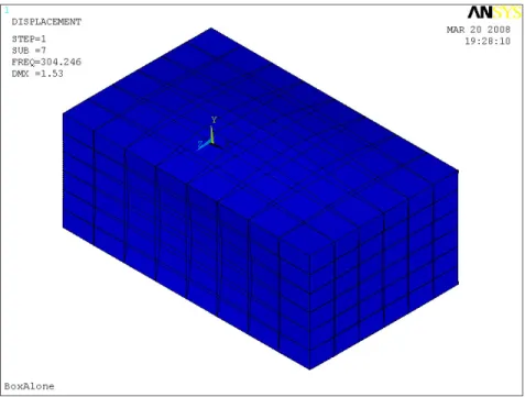
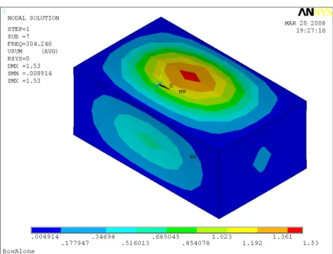
The casing of the electronic unit control is called box. The box is made out of constant thickness, uniform flat plates. Plates effectively welded together at edges, for instance common nodes have the same displacements in the 6DOFs. The Young’s modulus, E, was chosen to have the first mode shape at about 300 Hz. Table 4.1 shows the element used to made the Ansys model of the box, and Figure 4.2 the first mode shape resulting from the modal analysis.
Table 4.1: Properties of the Ansys model of the box Element Shell63 6 DOF s
4.3
Boards inside the box
There are two plates within the box, these represent the electronic boards inside the electronic control unit. The plates are constant thickness and are connected to the box along the two, opposite, short edges of the box. The boards are connected to the box such that common nodes have the same translational displacements on one side but the rotational DOFs are not coupled. On the other side couple the translational DOFs only in the direction normal to the board plane. CP elements were used to constrain the boards to the box. Each board have also two separate 1DOF point masses attached to the board via a spring/damper at different positions. This is to represent small components, like chips, on the board. The option on the M ASS21 elements were used to restrain the rotational DOF s of the elements while
4.3. BOARDS INSIDE THE BOX
Figure 4.1: Ansys model of the box meshed
CERIGelements were used to restrain the translational DOFs in the direction no normal to the board plane. The Young’s modulus, E, was adjusted to have for the heavy board the first mode shape at about 215 Hz and for the lighter board at about 125 Hz.
4.3.1 First board, the heavier one
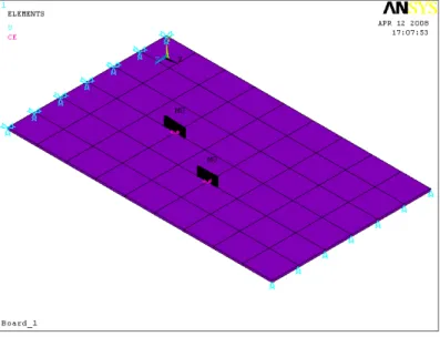
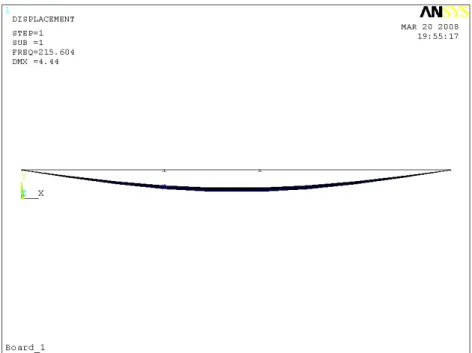
The two boards are constructed from the same elements and they have similar behaviour, because the only different between one and the other one is the location of the mass elements on the board and the thickness. That’s why afterward are shown the data and the results only for one of these, the heavier one. Table 4.2 reports the elements used to made the Ansys model while Figure 4.3 its model with the same constraints which restraining the board to the box, all translational displacements on one side and the translational DOF in the direction normal to the board plane. Figure 4.4 and Figure 4.5 show the mode shapes related to the board and to the chips.
4.3. BOARDS INSIDE THE BOX
Figure 4.2: Ansys model of the box, first mode shape
Table 4.2: Properties of the Ansys model of the first board Element Shell63 6 DOF s
Element M ass21 6 DOF s Element Combin37 6 DOF s Element CERIG 1DOF
4.3. BOARDS INSIDE THE BOX
4.3. BOARDS INSIDE THE BOX
(a) Side view
(b) 3D view
4.3. BOARDS INSIDE THE BOX
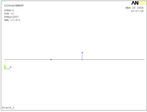
(a) First chip, 1007 Hz
(b) Second chip, 1424 Hz
4.4. ELECTRONIC CONTROL UNIT ATTACHED TO THE CCOC USING RIGID BRACKETS
4.4
Electronic control unit attached to the CCOC using
rigid brackets
4.4.1 Simulated ideal state
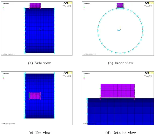
The simulated ideal state concern the model composed of the electronic control unit on the CCOC. In this section the box is attached to the CCOC at four points using rigid brackets. CERIG elements were used to restrain the box to the CCOC. The casing is essentially simply supported on one flange plane, with the other flange being translationally restrained except for the axial direction which is unrestrained. All rotational DOFs in the two flange planes remain unrestrained. This is also called real configuration because represents the real system which will operate, see Figure 4.6. This model is used to obtain the mounting point responses which will be used as input for the shaker and the monitoring point response that is the point of interest on the box.
(a) Side view (b) Front view
(c) Top view (d) Detailed view
4.4. ELECTRONIC CONTROL UNIT ATTACHED TO THE CCOC USING RIGID BRACKETS
4.4.2 Simulated tested state
The simulated ideal state concern the model composed of the electronic control unit on the shaker. This is also called test configuration. The high amplitude excitation issue is here analysed. One mounting point response along y from the above simulated ideal state was used as input for the shaker.
4.4.3 Harmonic analysis
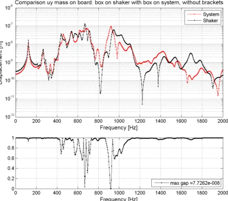
A harmonic force along z of 1 N was applied approximately at one fourth of the length of the model, close to the face where all DOFs of translation were fixed. The frequency range studied is from 0 to 2000[Hz]. Constant damping ratio, ξ, of 1.5% was used. The harmonic analysis was carried out for the simulated ideal state and for the simulated tested state. The displacement along y of the heavier chip on the lighter board was taken as monitoring point for both configuration to allow a comparison. The heavier chip has the natural frequency at 1007 Hz on a stiff board (rigid frame). The comparison between test and real configurations shows under or over testing for the monitoring over some frequency range, see Figure 4.7.
Figure 4.7: Real configuration and test configuration, box by rigid brackets on the CCOC, translation along y for the heavier chip on the lighter board
4.5. ELECTRONIC CONTROL UNIT ATTACHED TO THE CCOC USING BRACKETS
4.5
Electronic control unit attached to the CCOC using
brackets
4.5.1 Brackets
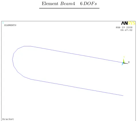
In general, the accessories are not attached rigidly to the casing, but using brackets enable to reduce the vibration environment transmitted to the accessories generated from the casing. Table 4.3 reports the element used to made the Ansys model, Figure 4.8 shows the shape of the bracket used. The Young’s modulus, E, and the thickness were set such that box starts to resonates rigidly on brackets at frequencies around 100 Hz.
Table 4.3: Properties of the Ansys model of the bracket Element Beam4 6 DOF s
4.6. ELECTRONIC CONTROL UNIT ATTACHED TO THE CCOC USING BRACKETS WITH ANTI-VIBRATOR MOUNTS
4.5.2 Simulated ideal and tested state
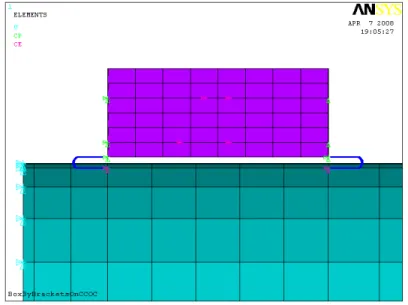
The electronic control unit is attached to the casing and to the shaker using the brackets for the simulated and tested state respectively. CERIG elements were used to restrain the brackets to the CCOC while CP elements were used to restrain the brackets to the box. The same consideration regards the other constraints, the input used for the shaker, the harmonic force, the damping, etc. described on the section 4.4 are still valid. In Figure 4.9 is shown a detailed view of the box attached to the CCOC using brackets, while the results from the harmonic analysis are shown in Figure 4.10.
Figure 4.9: Electronic control unit attached to the CCOC using brackets
4.6
Electronic control unit attached to the CCOC using
brackets with anti-vibrator mounts
4.6.1 Brackets with anti-vibrator mounts
In some application on the brackets are incorporated anti-vibration mounts, AV, between the bracket top and the box corners. The ant-vibration mounts are made from spring/damper elements which reduce more the vibration environment generated from the casing. Table 4.4 reports the element used to made the Ansys model while the anti-vibration mounts is not visible because the spring/damper is an element between two coincidental nodes. The Young’s modulus, E was selected
4.6. ELECTRONIC CONTROL UNIT ATTACHED TO THE CCOC USING BRACKETS WITH ANTI-VIBRATOR MOUNTS
Figure 4.10: Real configuration and test configuration, box by brackets on the CCOC, translation along y for the heavier chip on the lighter board
4.6. ELECTRONIC CONTROL UNIT ATTACHED TO THE CCOC USING BRACKETS WITH ANTI-VIBRATOR MOUNTS
such that box starts to resonates rigidly on springs at frequencies around 20 Hz.
Table 4.4: Properties of the Ansys model of the bracket with AV Element Beam4 6 DOF s
Element M ass21 6 DOF s Element Combin37 6 DOF s
4.6.2 Simulated ideal and tested state
The electronic control unit is attached to the casing and to the shaker using the brackets with the anti-vibrator mounts for the real and test configuration respectively. The same consideration regards the constraints, the input used for the shaker, the harmonic force, the damping, etc. described on the section 4.4 are still valid. The results from the harmonic analysis are shown in Figure 4.11.
Figure 4.11: Real configuration and test configuration, box by brackets with AV on the CCOC, translation along y for the heavier chip on the lighter board
4.7. DISPLACEMENT CONTROL FOR THE ELECTRONIC CONTROL UNIT ATTACHED TO THE CCOC USING BRACKETS
4.7
Displacement control for the electronic control unit
attached to the CCOC using brackets
This kind of test is used for fatigue issue because in some cases can lead to better simulation of the ideal state. In this test there are two points of interest: target and monitoring points. The target point is the point which has to have the same response for the real and test configurations. The monitoring points are the point whose the responses are measured to allow the comparison. The logic used for the displacement control can be summed up as followed: the output from the real configuration, box on the CCOC, is used as the target point for the box on the shaker where xsis found
as input to have the same response as the target point.
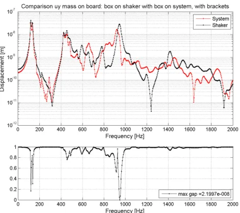
4.7.1 Top of the box as target point
The target is one point on the top of the box, whose the response must be the same for the box on the shaker and on the CCOC. The monitoring are points of interest, whose the response is measured in the two configurations for the box to allow the comparison. In this section the monitoring points are: mass one, mass two and on one point random chose on either boards. Where mass one has the natural frequency at around 1500 Hz on a stiff board (rigid frame), while mass two at around 1000 Hz. The board one has the first mode shape at about 215 Hz and the board two at about 125 Hz. The comparisons are shown in Figure 4.12, in Figure 4.13 and in Figure 4.14.
4.7.2 Point on the heavier board of the box as target point, board 1
The target is one point on the heavier board of the box, whose the response must be the same for the box on the shaker and on the CCOC. The monitoring are points of interest, whose the response is measured in the two configurations for the box to allow the comparison. In this section the monitoring points are: mass one, mass two and on one point random chose on either boards. Where mass one has the natural frequency at around 1500 Hz on a stiff board (rigid frame), while mass two at around 1000 Hz. The board one has the first mode shape at about 215 Hz and the board two at about 125 Hz. The comparisons are shown in Figure 4.15, in Figure 4.16 and in Figure 4.17.
4.7. DISPLACEMENT CONTROL FOR THE ELECTRONIC CONTROL UNIT ATTACHED TO THE CCOC USING BRACKETS
(a) Comparison uy of the top point on the box
(b) Comparison uy of the input for the box. System means one mounting point and shaker means the input found by the displacement control method
4.7. DISPLACEMENT CONTROL FOR THE ELECTRONIC CONTROL UNIT ATTACHED TO THE CCOC USING BRACKETS
(a) Comparison uy of mass 1 on board 1
(b) Comparison uy of mass 2 on board 1
4.7. DISPLACEMENT CONTROL FOR THE ELECTRONIC CONTROL UNIT ATTACHED TO THE CCOC USING BRACKETS
(a) Comparison uy of mass 1 on board 2
(b) Comparison uy of mass 2 on board 2
4.7. DISPLACEMENT CONTROL FOR THE ELECTRONIC CONTROL UNIT ATTACHED TO THE CCOC USING BRACKETS
4.7.3 Discussion
In this section the most general type of accessories was studied, an electronic control unit. In the first part an harmonic analysis was carried out for the accessory attached using different ways to the casing, for the simulated ideal state, and to the shaker, for the simulated test state. The response of a chosen point of interest for both configurations was taken as reference to allow the comparison. There was not an mitigation on the under and over testing using different kind of mounts but there was a reduction on the vibration environment transmitted to the box (electronic control unit). For this example, using simple bracket instead of rigid mount between the box and the casing the max amplitude is halved. Adding anti-vibrator mounts between the brackets and the box the max amplitude is reduced more than ten times. The issue is that in both cases the max amplitude is close to the natural frequencies regarding the modes shape of the mounts, whether of the brackets or of the anti-vibrator mounts. This means high stress for the mounts which became critical substructure for the assembly.
The next step was an harmonic analysis using the displacement control method on the accessory attached by brackets. As first case one point on the top of the box was taken as target point, this is easier way to measure the displacement. Afterward one point on one board within the electronic control unit was considered as target point, this is still reasonable way to do the test but obviously it is longer than the previous one. For both configurations with the exception of the frequency range regarding the mode shape of the brackets, there was under or over testing for the masses, the boards, the mounting points and the point of interest on the electronic control unit shown and quantified in the previous section.
The over or under testing originated one more from the different vibration environment which the accessory is subjected to when it is on the casing or when it is on the shaker. To sum up:
• the shaker is a very stiff body with its own dynamic, while the assembly has a totally different dynamic behaviour which influences the behaviour of the mounted substructure;
• the shaker can apply a same displacement for all mounting points whereas the assembly applies different displacement at each point;
• the assembly applies to the substructure six displacements for each mounting point: three rotations and three translation the shaker can only apply one of