dedicated in memory of Stefano Braccini, a colleague who greatly contributed to the ET project and a friend who left us.
European Commission
FP7, Grant Agreement 211743Einstein gravitational wave Telescope conceptual design
study
ET-0106A-10
This document has been edited by
F Acernese, S Aoudia, F Barone, M Beker, L Bosi, S Braccini, C Bradaschia, G Cella, T Dent, M Doets, V Fafone, P Falferi, J Franc, F Frasconi, A Freise, D Friedrich,
M Galimberti, G Gemme, E Genin, R Gouaty, C Gr¨af, I Harry, S Hild, K Kokeyama, T G F Li, M Lorenzini, H L¨uck, E Majorana, M Mantovani, I Martin, H M¨uller-Ebhardt, R Nawrodt,
G Parguez, A Pasqualetti, M Punturo, P Puppo,
D Rabeling, T Regimbau, S Reid, F Ricci, A Rocchi, B Sathyaprakash, L Storchi, S Tarabrin, A Th¨uring, J F J van den Brand, C Van Den Broeck, P Weßels, K Yamamoto
Author list:
ET Science Team
M Abernathy
1, F Acernese
2,3, P Ajith
30, B Allen
4, P Amaro-Seoane
54,32, N Andersson
5,
S Aoudia
54, P Astone
6,7, B Krishnan
4, L Barack
5, F Barone
2,3, B Barr
1, M Barsuglia
8,
M Bassan
9,10, R Bassiri
1, M Beker
11, N Beveridge
1, M Bizouard
12, C Bond
13, S Bose
14,
L Bosi
15, S Braccini
16, C Bradaschia
16,17, M Britzger
4, F Brueckner
18, T Bulik
19,
H Bulten
20, O Burmeister
4, E Calloni
2,21, P Campsie
1, L Carbone
13, G Cella
16,
E Chalkley
13, E Chassande-Mottin
8, S Chelkowski
13, A Chincarini
22, A Di Cintio
6, J Clark
26,
E Coccia
9,10, C N Colacino
16, J Colas
17, A Colla
6,7, A Corsi
30, A Cumming
1, L Cunningham
1,
E Cuoco
17, S Danilishin
23, K Danzmann
4, E Daw
28, R De Salvo
25, W Del Pozzo
11,
T Dent
26, R De Rosa
2,21, L Di Fiore
2, M Di Paolo Emilio
9, A Di Virgilio
16, A Dietz
27,
M Doets
11, J Dueck
4, M Edwards
26, V Fafone
9,10S Fairhurst
26, P Falferi
29,56,
M Favata
30, V Ferrari
6,7, F Ferrini
17, F Fidecaro
17,51, R Flaminio
31, J Franc
31,
F Frasconi
16, A Freise
13, D Friedrich
4, P Fulda
13, J Gair
26, M Galimberti
31, G Gemme
22, E Genin
17,
A Gennai
16, A Giazotto
16,17, K Glampedakis
40, R Gouaty
27, C Graef
4, W Graham
1, M Granata
8,
H Grote
4, G Guidi
33,34, J Hallam
13, G Hammond
1, M Hannam
26, J Harms
30, K Haughian
1,
I Hawke
5, D Heinert
18, M Hendry
1, I Heng
1, E Hennes
11, S Hild
1, J Hough
1, D Huet
17, S Husa
55,
S Huttner
1, B Iyer
38, I Jones
5, G Jones
1, I Kamaretsos
26, C Kant Mishra
38, F Kawazoe
4,
F Khalili
39, B Kley
18, K Kokeyama
13, K Kokkotas
40, S Kroker
18, R Kumar
1,
K Kuroda
41, B Lagrange
31, N Lastzka
4, T G F Li
11, M Lorenzini
33, G Losurdo
33,17, H L¨uck
4,
E Majorana
6, V Malvezzi
9,10, I Mandel
42,13, V Mandic
36, S Marka
50, F Marin
33, F Marion
27,
J Marque
17, I Martin
1, D Mc Leod
26, D Mckechan
26, M Mehmet
4, C Michel
31,
Y Minenkov
9, N Morgado
31, A Morgia
9, S Mosca
2,21L Moscatelli
6, B Mours
27,
H M¨uller-Ebhardt
4, P Murray
1, L Naticchioni
6,7, R Nawrodt
18, J Nelson
1, R O’ Shaughnessy
43,
C D Ott
30, C Palomba
6, A Paoli
17, G Parguez
17, A Pasqualetti
17,
R Passaquieti
16, D Passuello
16, M Perciballi
6, F Piergiovanni
33,34,
L Pinard
31, M Pitkin
1, W Plastino
44, R Poggiani
16, P Popolizio
17, E Porter
8,
M Prato
22, G Prodi
45,56, M Punturo
15,17, P Puppo
6, D Rabeling
20, I Racz
46, P Rapagnani
6,7,
V Re
9, J Read
37, T Regimbau
47, H Rehbein
4, S Reid
1, L Rezzolla
54,
F Ricci
6,7, F Richard
17, A Rocchi
9, R Romano
2, S Rowan
1, A R¨udiger
4,
A Samblowski
4, L Santamar´ıa
30, B Sassolas
31, B Sathyaprakash
26, R Schilling
4,
P Schmidt
26, R Schnabel
4, B Schutz
54, C Schwarz
18, J Scott
1, P Seidel
18, A M Sintes
55,
K Somiya
48, C F Sopuerta
49, F Speirits
1, L Storchi
15, K Strain
1, S Strigin
23, P Sutton
26,
S Tarabrin
4, B Taylor
4, A Th¨urin
4, K Tokmakov
1, M Tonelli
16,51, H Tournefier
27,
R Vaccarone
17, H Vahlbruch
4, J van den Brand
11,20, C Van Den Broeck
11, S van der Putten
11,
M van Veggel
1, A Vecchio
13, J Veitch;
26, F Vetrano
33,34, A Vicere
33,34, S Vyatchanin
23,
P Weßels
52, B Willke
4, W Winkler
4, G Woan
1, K Wojcik
26, A Woodcraft
53, K Yamamoto
35 Issue: 3 pre–releaseDate: May 20, 2011
1Department of Physics and Astronomy, The University of Glasgow, Glasgow, G12 8QQ, UK 2INFN, Sezione di Napoli, Italy
3Universit`a di Salerno, Fisciano, I-84084 Salerno, Italy
5University of Southampton, Southampton SO17 1BJ, UK 6INFN, Sezione di Roma 1, I-00185 Roma, Italy
7Universit`a ‘La Sapienza’, I-00185 Roma, Italy
8Laboratoire AstroParticule et Cosmologie (APC), Universit`e Paris Diderot, CNRS: IN2P3, CEA:DSM/IRFU,
Observatoire de Paris, 10 rue A.Domon et L.Duquet, 75013 Paris - France
9INFN, Sezione di Roma Tor Vergata I-00133 Roma, Italy 10Universit`a di Roma Tor Vergata, I-00133, Roma, Italy
11Nikhef, Science Park, Amsterdam, the Netherlands 12LAL, Universit´e Paris-Sud, IN2P3/CNRS, F-91898 Orsay, France
13University of Birmingham, Birmingham, B15 2TT, UK 14Washington State University, Pullman, WA 99164, USA
15INFN, Sezione di Perugia, Italy 16INFN, Sezione di Pisa, Italy
17European Gravitational Observatory (EGO), I-56021 Cascina (Pi), Italy 18
Friedrich–Schiller–Universit¨at Jena PF 07737 Jena, Germany
19Astronomical Observatory, University of Warsaw, 00-478, Warszawa, Poland 20VU University Amsterdam, De Boelelaan 1081, 1081 HV, Amsterdam, The Netherlands 21Universit`a di Napoli ‘Federico II’, Complesso Universitario di Monte S. Angelo, I-80126 Napoli, Italy
22INFN, Sezione di Genova, I-16146 Genova, Italy 23Moscow State University, Moscow, 119992, Russia 24INFN, Laboratori Nazionali del Gran Sasso, Assergi l’Aquila, Italy
25Universit`a degli Studi del Sannio, Benevento, Italy 26Cardiff University, Cardiff, CF24 3AA, UK
27LAPP-IN2P3/CNRS, Universit´e de Savoie, F-74941 Annecy-le-Vieux, France 28University of Sheffield, UK
29Istituto di Fotonica e Nanotecnologie, CNR-Fondazione Bruno Kessler, 38123 Povo, Trento, Italy 30Caltech–CaRT, Pasadena, CA 91125, USA
31Laboratoire des Mat´eriaux Avanc´es (LMA), IN2P3/CNRS, F-69622 Villeurbanne, Lyon, France 32Institut de Ci`encies de l’Espai, Campus UAB, Torre C-5, parells, 2na plantaES-08193 Bellaterra (Barcelona)
33INFN, Sezione di Firenze, I-50019 Sesto Fiorentino, Italy 34Universit`a degli Studi di Urbino ‘Carlo Bo’, I-61029 Urbino, Italy
35INFN, Sezione di Padova, Italy
36University of Minnesota, Minneapolis, MN 55455, USA
37Department of Physics and Astronomy, University of Mississippi, Oxford, US 38Raman research institute, Bangalore, India
39Moscow State University, Moscow, 119992, Russia
40Theoretical Astrophysics (TAT) Eberhard-Karls-Universit¨at T¨ubingen, Auf der Morgenstelle 10, D-72076 T¨ubingen,
Germany
41Institute for Cosmic Ray Research, University of Tokyo, Kashiwa, Chiba, Japan 42MIT Kavli Institute, Cambridge, MA 02139, US
43The Pennsylvania State University, University Park, PA 16802, USA
44INFN, Sezione di Roma Tre and Universit`a di Roma Tre-Dipartimento di Fisica, I-00146 Roma, Italy 45Universit`a di Trento, Trento, Italy
46KFKI Research Institute for Particle and Nuclear Physics, Budapest, Hungary
47Universit´e Nice ‘Sophia–Antipolis’, CNRS, Observatoire de la Cˆote d’Azur, F-06304 Nice, France 48Department of Physics, Tokyo Institute of Technology, Tokyo, Japan
49Institute of Space Sciences (CSIC-IEEC), Campus UAB, 08193 Bellaterra, Barcelona, Spain 50Department of Physics, Columbia University, New York, US
51Dipartimento di Fisica, Universit`a di Pisa, Pisa, Italy
52Laser Zentrum Hannover e.V., Hollerithallee 8, D-30419 Hannover, Germany 53Royal Observatory, Blackheath Avenue, Greenwich, SE10 8XJ, UK 54
Max–Planck–Institut f¨ur Gravitationsphysik, D-14476 Potsdam, Germany
55Departament de Fisica, Universitat de les Illes Balears, Cra. Valldemossa Km. 7.5, E-07122 Palma de Mallorca, Spain 56INFN, Gruppo Collegato di Trento, Italy
ET – Einstein gravitational wave Telescope – Design Study * A joint European Project Web:http://www.et-gw.eu Email: [email protected]
Abstract
This document describes the Conceptual Design of a third generation gravitational wave observatory named Einstein Telescope (“ET”). The design of this new research infrastructure has been realised with the support of the European Community’s Seventh Framework Programme (FP7/2007-2013) under grant agreement n 211743. In this document are described the fundamental design options, the site requirements, the main technological solutions, a rough evaluation of the costs and a schematic time plan.
This is a pre–release copy. In the current version this document could still contain wrong or contradictory statements.
Contents
1 Introduction to the ET project 8
1.1 Prologue . . . 8
1.2 Scientific targets of the ET observatory . . . 12
1.2.1 Fundamental physics . . . 12
1.2.2 Relativistic Astrophysics . . . 12
1.2.3 Cosmology . . . 13
1.3 Layout of the detector . . . 14
1.3.1 Size, shape and layout . . . 14
1.3.2 Quantum Noise . . . 15
1.3.3 Thermal Noise . . . 16
1.3.4 Seismic Isolation . . . 17
1.3.5 Newtonian gravity gradient noise . . . 17
1.3.6 Vacuum . . . 18
1.3.7 Noise budget . . . 18
1.4 Layout of the observatory . . . 19
1.5 Observatory timeline . . . 21
1.6 Observatory costs . . . 22
2 Science case 23 2.1 Introduction . . . 23
2.2 Executive Summary . . . 23
2.3 Sources of gravitational waves in ET . . . 27
2.3.1 Compact binary coalescences . . . 28
2.3.2 Continuous wave sources . . . 34
2.3.3 Burst sources . . . 38
2.3.4 Stochastic background . . . 42
2.4 Fundamental physics and strong field tests of GR . . . 45
2.4.1 Polarization of gravitational waves . . . 45
2.4.2 Bounding graviton mass . . . 45
2.4.3 Bounds on Brans-Dicke parameter . . . 47
2.4.4 Parametrized tests of post-Newtonian theory . . . 48
2.4.5 Measuring the dark energy equation of state and its variation with z . . . 49
2.4.6 Testing the uniqueness theorem of black hole spacetimes . . . 50
2.4.7 Testing the no-hair theorem using BH quasi-normal modes . . . 51
2.4.8 Limit on the maximum mass of compact stars . . . 52
2.5 Astrophysics . . . 53
2.5.1 Determining the neutron star equation of state from binary coalescences . . . 53
2.5.2 Neutron star physics from pulsar glitches . . . 55
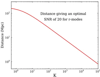
2.5.3 GW from the r-mode instability . . . 56
2.5.4 Solving the enigma of GRB progenitors . . . 58
2.5.5 Probing Core-Collapse Supernova Physics . . . 61
2.6 Cosmology and Cosmography . . . 63
2.6.1 Cosmography with a population of standard sirens . . . 63
2.6.2 Cosmological evolution of compact object populations . . . 68
2.6.3 Reconstruction of the evolution of compact binary coalescence rates by ET . . . 69
2.6.4 Intermediate mass black holes . . . 71
2.6.6 Primordial gravitational waves . . . 73
2.6.7 Confusion background from cosmological sources . . . 76
2.7 Computing Challenges . . . 79
2.7.1 Detection Strategies requirements . . . 79
2.7.2 Computing evolution . . . 84
2.7.3 Impacts on data analysis . . . 87
2.7.4 Conclusions . . . 88
3 Site and infrastructures 90 3.1 Description . . . 90
3.2 Executive Summary . . . 90
3.3 Infrastructure Reference Design . . . 91
3.4 Site specific noise . . . 95
3.4.1 Seismic noise . . . 96
3.4.2 Geological and geographic observations . . . 102
3.5 Newtonian noise . . . 104
3.5.1 A simplified NN estimate . . . 104
3.5.2 Finite element models . . . 107
3.5.3 Ambient NN subtraction . . . 110
3.5.4 NN subtraction from periodic sources . . . 116
3.6 Site selection . . . 117
3.6.1 Measurement sites . . . 118
3.6.2 Results from a selection of sites . . . 120
3.7 Infrastructure realization . . . 125 3.7.1 Infrastructure overview . . . 125 3.7.2 Caverns . . . 128 3.7.3 Tunnels . . . 132 3.7.4 Shafts . . . 139 3.7.5 Final remarks . . . 140 3.8 Vacuum systems . . . 140 3.8.1 Introduction . . . 140
3.8.2 Average base pressure in the arm pipes . . . 141
3.8.3 The arm pipes . . . 143
3.8.4 Pipe Assembly . . . 145
3.8.5 Pipe pumping system . . . 149
3.8.6 Pipe bake-out system . . . 149
3.8.7 Cryotraps . . . 150
3.8.8 Towers . . . 150
3.8.9 Tower pumping system . . . 151
3.8.10 Valves . . . 151
3.9 Cryogenic service infrastructures . . . 151
3.9.1 The ET cryostats . . . 151
3.9.2 The LF-interferometer cryotraps . . . 153
3.9.3 The cryogenic infrastructure based on pulse tube cryo-coolers . . . 163
3.9.4 The cryogenic fluid approach . . . 166
3.9.5 Cryogenic plant control . . . 168
3.9.6 A future development: lowering the temperature with Helium II . . . 168
3.9.7 R&D in Cryo-coolers . . . 169
3.10 Cost estimate for the Intrastructure Reference Design . . . 170
3.11 Technologies to be developed . . . 171
3.11.1 Introduction . . . 171
3.11.2 Research and development program . . . 172
3.11.3 Coordination of activities . . . 172
3.11.4 Consolidation of infrastructure requirements . . . 173
4 Suspension systems 174 4.1 Description . . . 174
4.2 Executive summary . . . 174
4.3 Mechanics of the suspension upper stages . . . 176
4.3.1 LF interferometer . . . 176
4.3.2 HF interferometer . . . 192
4.3.3 Upper-lower suspension interface . . . 196
4.4 Mirror last stage suspension . . . 197
4.4.1 Material selection for the last stage suspension . . . 198
4.4.2 Suspension thermal noise model . . . 204
4.4.3 Normal mode formalism . . . 205
4.4.4 Thermal noise computation of LSS for the LF interferometer . . . 205
4.4.5 The payload of the HF interferometer . . . 207
4.4.7 The payload local control for ET . . . 213
4.4.8 The coil–magnet actuators . . . 215
4.4.9 The electrostatic actuators . . . 219
4.5 Technologies to be developed . . . 222
4.5.1 R&D on the production of high purity silicon crystal fibre for the LF interferometer . . . 222
4.5.2 R&D on the bonding of silicon for the production of quasi-monolithic silicon suspensions 224 4.5.3 R&D on surface losses in silicon . . . 225
4.5.4 R&D on a new generation of monolithic accelerometer for the suspension control. . . 226
4.6 The cost evaluation of the suspension system . . . 229
5 Optical design 231 5.1 Executive Summary . . . 231
5.2 Description . . . 233
5.3 Review on the geometry of the observatory . . . 235
5.3.1 The L-shape . . . 235
5.3.2 The triangle . . . 236
5.4 Optical layout . . . 239
5.4.1 Constraints on the optical layout from classical noise sources . . . 240
5.4.2 A xylophone design for ET . . . 242
5.4.3 Arm cavity design . . . 243
5.4.4 Central interferometer design . . . 246
5.5 Quantum noise reduction techniques . . . 247
5.5.1 Review of quantum non-demolition topology options . . . 248
5.5.2 Alternative topologies and interferometry types . . . 250
5.5.3 Quantum noise reduction with squeezed states of light . . . 250
5.5.4 Filter cavities . . . 256
5.6 Main interferometer optical components . . . 261
5.6.1 Bulk material selection . . . 261
5.6.2 Coating material selection . . . 265
5.6.3 Thermal noise estimates for reflective components . . . 269
5.6.4 Thermal noise estimates for transmittive components . . . 274
5.6.5 LF interferometer large mirror definition . . . 276
5.6.6 HF interferometer large mirror definition . . . 280
5.6.7 Mirror surface defects . . . 282
5.7 Standard Optical Technologies . . . 283
5.7.1 Injection system . . . 284
5.7.2 Detection system . . . 289
5.7.3 Main control and alignment strategies . . . 293
5.7.4 Thermal effects and their compensation . . . 300
5.8 Rough cost evaluation . . . 303
5.9 Technologies to be developed / R&D . . . 304
5.9.1 Thermal noise reduction due to LG modes . . . 304
5.9.2 Thermal noise reduction due to Khalili cavities and etalons . . . 305
5.9.3 Coating research . . . 306
5.9.4 Waveguide grating mirrors . . . 307
5.9.5 Speedmeter topology . . . 308
6 Overall budget and timeline considerations 310 6.1 ET Timeline . . . 310 6.2 ET costs . . . 311 6.2.1 Site costs . . . 314 6.2.2 Vacuum costs . . . 316 6.2.3 Cryogenics costs . . . 316 6.2.4 Suspensions costs . . . 319 6.2.5 Optics costs . . . 321 Appendices 324 A Science Case 324 A.1 Detection Rate of BNS Systems in ET . . . 324
A.2 The Spin-Down Limit signal amplitude . . . 324
A.3 Search sensitivity to Continuous Wave sources . . . 324
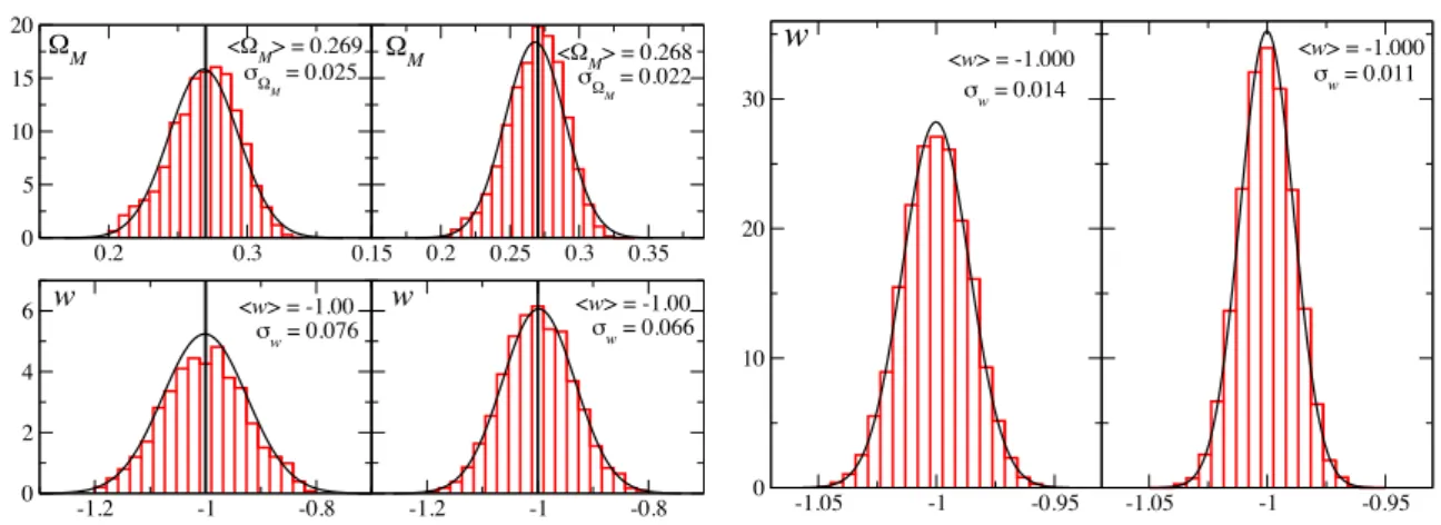
A.4 Measuring w(z) Using GW and CMB Observations . . . 325
A.5 Sources of primordial stochastic GW background . . . 325
A.5.1 Stochastic GW background in Pre-Big-Bang cosmology . . . 325
A.5.2 GW background from cosmic string networks . . . 326
A.5.4 GW from reheating after hybrid inflation . . . 326
A.6 Moore’s Law . . . 327
A.7 20 years of parallelization . . . 327
A.8 Manycore architectures . . . 328
A.9 Emerging technologies for distributed computing . . . 328
B Site and Infrastructure 329 B.1 Measurement methodology and data analysis . . . 329
B.2 Seismic measurement results . . . 330
B.3 The geometric configuration factor . . . 341
B.4 Diffusely emitting surfaces . . . 343
B.5 Vacuum System Parameters . . . 343
C Suspensions 344 C.1 Cryogenic compatibility of materials for Superattenuator construction . . . 344
C.2 Geometric anti-springs as seismic attenuation filters . . . 345
C.3 The LIGO active seismic filters . . . 347
D Optics 349 D.1 Table of layout parameters . . . 349
D.2 Quantum noise features of different topologies . . . 350
D.3 Filter cavities . . . 355
D.3.1 Restrictions for the baseline length of the filter cavity . . . 355
D.3.2 Determination of the required filter parameters . . . 358
D.3.3 Robustness of the design parameters . . . 361
D.3.4 Scattering light noise in optical cavities . . . 361
D.3.5 Noise couplings . . . 370
D.4 Thermal noise of the ET-LF interferometer . . . 375
D.5 Parametric instability . . . 377
D.6 Holographic noise . . . 382
D.7 Displacement-noise-free interferometry . . . 383
D.8 Alternative to laser interferometry: atomic sensor . . . 384
E Properties 385 E.1 Optics properties data base . . . 385
E.2 Mechanical properties of optical materials . . . 386
E.3 Thermal properties of optical materials . . . 387
7 Acknowledgements 390
Bibliography 391
1
Introduction to the ET project
1.1
Prologue
The first generation of interferometric gravitational wave (GW) detectors (GEO600 [1], LIGO [2], TAMA [3], Virgo [4]) have reached or approached their design sensitivities, and thus demonstrated the effectiveness of the working principle. The major detectors currently operative are enhanced versions of the first generation (Virgo+ and eLIGO), with higher laser power and some technological improvements.
Advanced detectors (like “Advanced LIGO”([5], [6]) and “Advanced Virgo” ([7])), also called the second gen-eration, will show a sensitivity improved roughly by a factor of ten with respect to the initial interferometers. They are based on technologies currently available, sometimes tested in reduced scale prototypes, but still to be implemented in full scale. According to the current models of GW sources, the sensitivity of the advanced inter-ferometers is expected to guarantee the detection of signals generated by astrophysical sources within months to a year at most. For example, at the nominal sensitivity of the advanced detectors, the expected detection rate of the GW signal generated by a binary system of coalescing neutron stars is about a few tens per year. But apart from extremely rare events, the expected signal-to-noise ratio (SNR) of these detections obtained with the advanced detectors is too low for precise astronomical studies of the GW sources and for complementing optical and X–ray observations in the study of fundamental systems and processes in the Universe.
These considerations led the GW community to start investigating a new (third) generation of detectors. In particular, the European Commission supported the institutions in Table1 to realise this design study within the Seventh Framework Programme (FP7-Capacities). With a considerably improved sensitivity, such new machines of the third-generation will open the era of routine GW astronomy and with the Einstein Telescope (ET) project Europe will lead this scientific revolution. Since the first detection of a GW signal is expected to occur in the advanced interferometers, the evaluation of the scientific impact of ET it is especially focused on the observational aspects rather than on the detection capabilities.
To realise a third-generation GW observatory with a significantly enhanced sensitivity (we defined a target of a factor of ten improvement in sensitivity for ET with respect to the advanced detectors over a wide frequency range), several limitations of the technologies adopted in the advanced interferometers must be overcome and new solutions to be developed are proposed in this document to reduce the fundamental and technical noises that will limit the next generation machines.
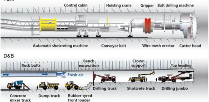
However, the first and main target of this document is the definition of the requirements and of the main characteristics of the site hosting ET, the design of the key elements of the research infrastructure, the rough evaluation of the costs and of the timeline of its implementation. To understand the importance and the need of the site and infrastructures in the ET design it is worth to recall the history of the current GW detector infrastructures, shown in Fig.1.
Table 1: Institutions participating (“Beneficiaries”) to the ET design study.
Institute Country
European Gravitational Observatory Italy–France Istituto Nazionale di Fisica Nucleare Italy Max-Planck-Gesellschaft zur F¨orderung der Wissenschaften e.V.,
acting through Max-Planck-Instit¨ut f¨ur Gravitationsphysik Germany Centre National de la Recherche Scientifique France
University of Birmingham United Kingdom
University of Glasgow United Kingdom
NIKHEF The Netherlands
Figure 1: Evolution of the first and second generation GW detectors. Time is on the horizontal axis, detector perfor-mance in the vertical one. When the advanced detectors will be operative the hosting infrastructures will be more than 20 years old and any further improvement of performance (sensitivity) will be suppressed by the limitation imposed by the infrastructures. (slide presented by M. Punturo at the GWDAW meeting, Rome Jan. 2010).
Current and advanced detectors are using the same infrastructure that will be about 20 years old when the second generation will be online. Further improvements of the sensitivity will be limited by the constraints of the site and infrastructure (arm length, local seismic noise, absence of cryogenic apparatus, vacuum pipe size . . . ). Indeed, in order to realise a third-generation GW observatory like ET, an infrastructure hosting several detectors that evolve for many decades is crucial.
Box 1.1 The Einstein Telescope at a glance
The Einstein gravitational–wave Telescope will be an observatory of the third generation aiming to reach a sensitivity for GW signals emitted by astrophysical and cosmological sources about a factor of 10 better than the advanced detectors currently being built. An observatory with such a level of sensitivity will open the era of routine GW astronomy.
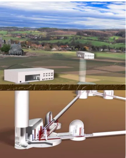
An artist’s impression of ET is given in Fig. 2, below. The main purpose of the ET project is the realisation of an infrastructure (an“observatory”) capable of hosting more than one GW detector. This infrastructure will be usable for many decades, while the implemented detectors will undergo successive upgrades or replacements according to the current state of the art of interferometer technologies.
Figure 2: Artist’s view of the Einstein Telescope
To reduce the effect of the residual seismic motion, thus allowing a better sensitivity at low frequen-cies (between 3 and 100 Hz), ET will be located underground at a depth of about 100 m to 200 m and, in the complete configuration, it will consist of three nested detectors, each in turn composed of two interferometers (xylophone configuration). The topology of each interferometer will be the dual-recycled Michelson layout with Fabry–Perot arm cavities, with a length of about 10 km. The xy-lophone configuration of each detector devotes one interferometer to the detection of the low-frequency components of the GW signal (2–40 Hz) while the other is dedicated to the high-frequency compo-nents, each interferometer adopting different, optimal technologies. In the former (ET-LF), operating at cryogenic temperature, the thermal, seismic, gravity gradient and radiation pressure noise sources will be particularly suppressed; in the latter (ET-HF) the sensitivity at high frequencies will be im-proved through the high laser light power circulating in the Fabry–Perot cavities, and through the use of frequency-dependent squeezed light technologies. The target sensitivity of the ET observatory, at the current level of understanding, is shown in figure7.
Box 1.2 Detecting Gravitational Waves
Gravitational waves change distances between objects, while the objects themselves locally remain at rest, by changing the metric of space-time. These changes occur with opposing sign for orthogonal directions, as illustrated in figure3for one polarisation of a gravitational wave incident perpendicular to the paper (h+: see box2.2for more details).
Figure 3: The effect of gravitational waves on the distances between objects. While the mirrors remain locally at rest the metric gets changed by the gravitational wave. The figure shows the effect of a sinusoidal gravitational wave with period τ, for different times t. The distances measured between the mirrors change by ±δ�.
A Michelson interferometer is ideally suited to measuring this effect. The measurement principle is shown in figure4. A laser beam is split into two partial beams, sent along the interferometer arms, where it experiences a phase shift by the metric change of the gravitational wave, is reflected at the end and returns to the beam splitter, where it is recombined. The interference condition at the beam splitter, i.e. the phase relation of the two returning beams, determines the intensity on the photo detector. Three different phase relations are shown in figure 4. The relative length change of the interferometer arms can hence be detected by measuring the power at the output port. Although the measurement principle is very simple, for getting the best possible sensitivity all influences that change the geometrical or optical arm length or that cause a signal in the detected photo-current mimicking a gravitational wave have to be minimised, resulting in very sophisticated and complex instruments.
Mirror Mirror BeamͲ splitter Interference Photodetector Mirror Mirror BeamͲ splitter Interference Photodetector Mirror Mirror BeamͲ splitter Interference Photodetector
Figure 4: Michelson interferometer principle for gravitational wave detection, showing three different interference conditions resulting in different brightness at the output port.
1.2
Scientific targets of the ET observatory
1.2.1 Fundamental physics
Astronomical sources of gravitational waves are essentially systems where gravity is extremely strong, and are often characterized by relativistic bulk motion of massive objects. The emitted radiation carries an uncorrupted signature of the nature of the space-time geometry, and is thus an invaluable tool to understand the behaviour of matter and geometry in extreme conditions of density, temperature, magnetic fields and relativistic motion. Here are some examples of how GW observations can impact fundamental physics.
In Einstein’s theory, gravitational radiation travels at the speed of light and has two polarization states. In alternative theories of gravity one or both of these properties might not hold, owing to the presence of massive gravitons, or a scalar field mediating gravity in addition to the tensor field. Current experimental tests of gravity, as well those afforded by the data from the Hulse-Taylor binary, are consistent with both Einstein’s theory and one of its alternatives called the Brans-Dicke theory. Gravitational wave detectors will bring these theories vis-a-vis observations that could decisively rule out one or the other.
According to Einstein’s gravity the space-time in the vicinity of black holes is described by a unique geometry called the Kerr solution. Observation of the radiation from the infall of stellar-mass black holes into intermediate-mass black holes will make it possible to test such uniqueness theorems. X-ray astronomy has provided firm indirect evidence that intense sources of X-rays may well host a black hole. An unambiguous signature of the black hole geometry, however, could eventually be provided by the detection of black hole quasi-normal modes: gravitational radiation with characteristic frequencies and decay times that depend only on the mass and spin angular momentum of the black hole. Failure to detect such radiation from, for example, a newly formed black hole would mean that gravity is more exotic than we currently believe, and might reveal new phases of matter at extremely high densities.
The most attractive versions of string theory require a ten- or eleven-dimensional space-time, far above those that we perceive. In certain phenomenological models at the interface of string theory and cosmology, what we perceive as a four-dimensional Universe could be one part, or “brane”, within a higher dimensional “bulk” Universe. The extra spatial dimensions may be compact and sub-millimetre-scale, or even macroscopically large, if their geometry has properties known as “warping”. The key feature of brane-world theories is that gravitational interactions, and in particular gravitational waves, propagate in the bulk, while other interactions are restricted to the brane, which partly explains why gravity is so weak. Third-generation detectors offer the exciting possibility of observing radiation from the bulk and thereby exploring whether the Universe has large extra dimensions.
1.2.2 Relativistic Astrophysics
Astronomy has revealed a Universe full of diverse and exotic phenomena that remain enigmas decades after their discovery. Supernovae are the end-states of stellar evolution, resulting in gravitational collapse followed by a huge explosion of the formerly infalling matter. Gamma-ray bursts are intense sources of gamma radiation that last only a few seconds to minutes yet emit more energy than a star does in its entire lifetime. Radio pulsars are compact objects as massive as the Sun but only about 10 km in size, and the regularity of their radio pulses and occasional glitches in that regularity have remained puzzles for a long time after their discovery three decades ago. Transient radio sources thousands of light years away are associated with magnetic fields so strong that the emitted radiation could break down terrestrial radio stations.
The source in question in each case is believed to be couched in dense environs and strong gravitational fields and, therefore, a potential source of gravitational radiation. For example, gamma-ray bursts could be produced by colliding neutron stars which are electromagnetically invisible for most of their lives but are very powerful emitters of GWs. Transient radio sources could be the result of quakes in neutron stars with concomitant emission of GWs. Observing such ‘multi-messengers’ (sources that are strong emitters of both EM and GW radiation) will help understand phenomena that have remained puzzles for decades.
The centre of every galaxy is believed to host a compact object a million to a billion times as massive as our Sun, a powerful emitter of optical, radio and other radiation. What is the nature of this object? How and when did it form? Did it form from small 100-solar-mass seeds and then grow by accreting gas and other compact objects? What is its relation to the size of the galaxy as a whole? These are some of the questions which a model of the formation of structure in the Universe must answer. While electromagnetic observations have provided valuable data, ET can explore the population of stellar mass and intermediate mass black holes as a function of redshift and shed light on black hole demographics, their mass distribution and growth.
ET will also be sensitive to a population of sources at very high redshifts, helping us study cosmological evolution of sources, the history of star formation and its dependence on the matter content of the Universe, and the development of large-scale structure in the Universe.
1.2.3 Cosmology
The twentieth century was the golden age of cosmology. With the advent of radio and microwave astronomy it was possible to finally address key questions about the origin of the Universe. The cosmic microwave background (CMB) is a relic radiation from the hot Big Bang that is believed to have been the initial condition for primordial nucleosynthesis. Since the early Universe was very dense, this radiation was in thermal equilibrium with matter for about 380,000 years after the Big Bang and cannot directly reveal the conditions in the very early phases of the Universe’s history. The most direct way of observing the primeval Universe is via the gravitational window with a network of two or more detectors. From fairly general assumptions one can predict the production of a stochastic background of GWs in the early Universe, which travel to us unscathed as a consequence of their weak coupling to matter.
The most amazing aspect of the Universe is that only about 4% of its energy density appears in the form of visible matter, the rest being dark matter and dark energy. In order to understand the behaviour of these ‘dark’ contents it is necessary to have a standard candle—a population of sources whose distance from Earth can be inferred from their luminosity. Compact binaries are an astronomer’s ideal standard candle. By measuring the signature of the gravitational radiation they emit, it is possible to infer their intrinsic parameters (e.g. the masses and spins of the component objects) and accurately deduce their luminosity distance. In fact, compact binaries eliminate the need to build a cosmic distance ladder—the process by which standard candles at different distances are calibrated in astronomy since there is no source that is suitable at all distances.
The synergy of multi-messenger astronomy is nowhere more apparent than in the use of standard sirens of gravity to test the concordance model of cosmology. ET might detect several hundred compact binary coalescence events each year in coincidence with short-hard gamma-ray bursts, provided, of course, the two are related. While gravitational observations would provide an unambiguous measure of the luminosity distance, the host galaxy of the GRB could be used to measure the redshift. By fitting the observed population to a cosmological model, it will be possible to measure the Hubble parameter, dark matter and dark energy densities, as well as the dark energy equation-of-state parameter.
The early history of the Universe may have witnessed several phase transitions as the temperature decreased through the energy scales of a Grand Unified Theory (GUT) and electroweak symmetry-breaking, and eventually to the current state in which we see four different fundamental interactions. During some phase transitions, cosmic strings form as one-dimensional topological defects at the boundaries of different phases. Vibrations of these strings at the speed of light can sometimes form a kink that emits a burst of gravitational radiation. The spectrum of such radiation has a unique signature that can help us detect cosmic strings and measure their properties, and thus provide a glimpse of the Universe as it underwent phase transitions.
Perhaps the most exciting discovery of the new window will be none of the above. If astronomical history is any example, gravitational astronomy should unveil phenomena and sources never imagined in the wildest theories—a possibility of any new observational tool.
1.3
Layout of the detector
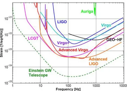
Figure 5: Sensitivities of gravitational wave detectors from the first to the third generation.
The sensitivity of gravitational wave de-tectors improved considerably from the bar detectors to the first generation of interferometric detectors, which are cur-rently being upgraded to the ‘advanced’ generation. The corresponding sensitivi-ties are shown in figure 5. In order to achieve the scientific goals stated above, the sensitivity in comparison to the sec-ond generation of gravitational wave de-tectors must be improved by about an or-der of magnitude over the entire detec-tion frequency band ranging from 10 Hz to about 10 kHz. Frequent observation of low-frequency sources, e.g. intermediate mass black holes, requires an extension of the detection range towards lower frequen-cies.
The initial sensitivity goal for the Einstein Telescope, estimated at the start of the De-sign Study, as shown in figure5, was driven
by the need to get frequent high Signal to Noise Ratio (SNR) events for routine gravitational wave astronomy. The high-frequency sensitivity was given by the maximum power feasible, the mid-frequency range was governed by thermal noises and the low-frequency range by either thermal or seismic noises. The initial estimates have been refined during the design study and finally resulted in the sensitivity shown in figure13.
1.3.1 Size, shape and layout
The conceptual design of a project of this financial scale (see table212) has to be based on well proven and experimentally tested techniques. To achieve the sensitivity that the Einstein Telescope project aims for, on the other hand, it will be necessary to exploit all state-of-the-art technologies and drive them to their physical limits.
Figure 6: Three nested detectors in a triangu-lar arrangement will form the final Einstein Telescope geometry. This sensitivity can only be reached by significantly increasing
the size of the detector beyond the size of currently available in-struments (i.e. 3 km for Virgo and 4 km for LIGO) and going to an underground location, where the seismic noise is lower than at the surface. Only by increasing the arm length to 10 km can the influence of unavoidable displacement noises be lowered to a tolerable level.
In its final construction stage the Einstein Telescope will con-sist of three nested detectors, which will be arranged in a tri-angular pattern as shown in figure 6. In contrast to the tradi-tional L-shaped geometry of the first and second generations of gravitational wave detectors this arrangement is equally sensi-tive for both polarisations of the gravitational wave. Addition-ally it shows a more isotropic antenna pattern compared to the L-shaped detectors, as shown in figure 16. The overall frequency range covered will reach from a few Hertz to about 10 kHz.
Each individual detector in turn will comprise two interferometers, one specialised for detecting low-frequency gravitational waves and the other one for the high-frequency part. The sensitivity goal for each interferometer
is shown in figure7. Each individual interferometer has a classical dual-recycled Michelson topology with arm cavities. This is a mature technique, well tested in laboratory experiments, and currently being set up for the second-generation detectors, Advanced LIGO and Advanced Virgo. More elaborate topologies like Sagnac interferometers or optical bars using Quantum Non-Demolition (QND) techniques do not promise significant advantages and have not yet reached the level of maturity required for a project of this scale.
1.3.2 Quantum Noise
In order to achieve a sufficient sensitivity at high frequencies the light power in the arms of the high-frequency interferometer needs to be increased to the megawatt range. Thermal noise considerations on the other hand require cryogenic optics to reach the sensitivity goal at low frequencies.
100 101 102 103 104 10−25 10−24 10−23 10−22 Strain [1/sqrt(Hz)] Frequency [Hz] ET−D−LF ET−D−HF ET−D sum
Figure 7: Sensitivity of the Einstein Telescope in the ‘xylophone’ con-figuration. The sensitivity of the low-frequency cryogenic in-terferometer is shown in the dashed dark blue curve and the one of the high-frequency room temperature one in a dashed blue-green tone. The sum of both is given by the solid bright red curve.
Operating cryogenic optics at a level of several megawatt of light power presents a serious technological challenge which is extremely hard to master. Even for the best mirrors that state-of-the-art coating technology can produce, the residual ab-sorption of only about one ppm leads to an absorbed power of several Watt at a cir-culating light power level in the megawatt range. The resulting thickness of the sus-pension fibres, which would be needed to remove the heat, would spoil the per-formance of the ultra low loss suspen-sion. The Einstein Telescope will there-fore be realised in what we call a ‘xy-lophone’ arrangement, where each single detector is split into two interferometers, leading to sensitivities as shown in fig-ure 7. The one dedicated for detecting high-frequency gravitational waves in the range from about 30 Hz to 10 kHz will be operated at room temperature, use fused silica optics with a diameter of about 60 cm and a mass of about 200 kg each, have a light power of about 3 MW in the
interfer-ometer arms, and run with broadband tuned signal recycling. The cryogenic, low-frequency one, operated at a temperature of 10 K and aimed at the frequency range from 1.5 Hz to 30 Hz, will use detuned signal recycling, have a light power of 18 kW in the interferometer arms, and silicon mirrors with a diameter of about 40 cm and a mass of about 200 kg. The cryogenic optics will either be made of sapphire or, more likely, of silicon. The dimensions will partly be determined by the maximum available bulk material size and otherwise be compa-rable to the room temperature ones. A summary of the main parameters for the high and low temperature interferometers is given in table10.
The high mirror mass will not only keep radiation pressure effects low but also allow larger sized beam spots on the mirror surfaces for lowering thermal noise effects. This split detector arrangement also offers an elegant solution for the challenge that radiation pressure noise and shot noise scale in opposite ways with light power and cannot individually be optimised in a single interferometer. In an interferometer using classical states of light the so-called Standard Quantum Limit (SQL) determines the lower limit for the quantum noise. For each frequency there is a different optimal compromise between shot noise and radiation pressure noise, meaning that in a single interferometer the SQL cannot be reached for all frequencies simultaneously.
Figure 8: Scheme for generating squeezed light. For details see section5.5.3
It can only be overcome if non-classical light with correlations between the phase and the amplitude quadratures is used, so-called squeezed light. In the shot noise dominated frequency range squeezed light is used, which shows lower phase fluctuations at the cost of the amplitude fluctuations in comparison to classical laser light in the interferometer arms. In the low-frequency, radiation pressure dominated range the fluctuations need to be lowered in the amplitude quadrature. This goal can be achieved by reflecting squeezed light off a filter cavity (see figure165).
The usage of squeezed light is currently tested in the existing grav-itational wave detectors and is foreseen as an add-on to the second generation. Squeezing levels over the full observation band width of up to 10 dB, and stable long-term operation and best squeezing values of almost 13 dB have been demonstrated [8]. For the Einstein Tele-scope we assume 15 dB initial squeezing level at the squeezing source and an effective squeezing level of 10 dB to be available (equivalent in shot noise reduction to a laser power increase of a factor of 10). The squeezing level, and with it the sensitivity improvement that can be reached, depends on the optical losses in the squeezer, the filtering optics, the interferometer, and all optical devices on the way to the photodetector, including the photodetector efficiency itself. Optical losses easily add vacuum fluctuations to the squeezed quadrature and hence reconvert squeezed light into classical light. It will therefore be essential to keep the optical losses as low as possible. Optical losses of
75 ppm per round trip are currently achievable with state-of-the-art techniques and are used as a conservative estimate for the filter cavities.
1.3.3 Thermal Noise
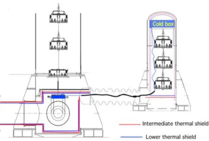
Figure 9: Scheme for cooling the mirrors. For details see section3.9
Reaching the sensitivity goal at low frequencies requires a significant re-duction of thermal noises compared to the first and second generations of gravitational-wave detectors, which can be achieved by operating the mirrors at cryogenic temperatures as low as 10 K.
Cryogenic operation is also foreseen for the final stage of the planned Japanese gravitational wave detector LCGT. At these low temperatures fused silica has a low mechanical quality factor and becomes unusable. Silicon and sapphire show excellent low-temperature behaviour (see sec-tionE) and are good candidates for cryogenic gravitational wave detec-tors. Its availability in large
quan-tities and good purity through the semiconductor industry makes silicon a promising candidate for the Einstein Telescope cryogenic optics. Some quantities such as the temperature dependence of the refractive index at low
temperatures and the residual optical absorption in ultra pure silicon, although assumed to be good enough for use in ET, are currently not known and need to be investigated in R&D activities.
Removing the heat generated by laser light being absorbed at the mirror surfaces without introducing excess vibration levels poses another technical challenge. As thermal radiation does not provide sufficient coupling at cryogenic temperatures this heat removal has to be done by thermal conduction of the suspension fibres. The resulting requirement for the thickness of the silicon suspension fibres needs to be balanced against good seismic isolation properties of thin fibres. The vibration level of cryo coolers, which could be placed close to the optics, threatens the low-frequency sensitivity (see section3.9.3). R&D in active and passive vibration suppression is still required to sufficiently cut the remaining noise level down for use in the Einstein Telescope. Cryo fluids, like superfluid Helium II, which are cooled down at a remote location above ground, are available as a seismically more quiet alternative (see section 3.9.6). The final operating temperature for ET remains to be fixed in a technical design phase. The cooling capabilities foreseen so far will allow mirror temperatures as low as 10 K.
1.3.4 Seismic Isolation
Figure 10: Schematic view of the Virgo Super-attenuator. See also section4
The main optics for the Einstein telescope need to be very well isolated against seismic ground motion. For the second genera-tion of gravitagenera-tional wave detectors both active and passive isola-tion strategies are being pursued. In the advanced LIGO detec-tors a two stage system actively isolates a platform from ground motion, from which the main optics are suspended by quadruple pendulums. The passive strategy employed at the Virgo detector demonstrated an excellent performance over the full frequency range (see figure117) and is foreseen as the reference solution for the Einstein telescope. The horizontal isolation is achieved with a six-stage pendulum system, whereas for the vertical degree of freedom cantilever springs are used. The pendulum suspension system itself is supported by a platform resting on an inverted pendulum, which provides additional horizontal seismic isolation (see figure115). All mechanical resonances of the whole structure are actively damped to avoid resonant mechanical amplification of ground motion. The overall height of the suspension system is about 17 m, requiring correspondingly tall vacuum chambers and caverns.
1.3.5 Newtonian gravity gradient noise
Newtonian gravitational interactions between the optics and the surrounding soil provide a direct coupling mechanism of ground motion to the interferometer test masses (see also section3.5). As the resulting, so-called gravity gradient noise cannot be shielded from the mirrors, a location has to be found where this seismic motion is minimal and the surrounding soil as homogeneous as possible. This goal can be achieved in an underground location in a seismically quiet region. Preliminary measurements show that a depth of 100 to 200 m in a remote location with low population density provides sufficiently low seismic motion. The potential
of measuring the ambient seismic motion, feeding it into a gravity gradient noise model, and then subtracting the predicted effect from the interferometer output signal has been investigated. Initial results are promising, and are interesting also for the second generation of gravitational wave detectors, but investigations need to be continued in an R&D programme (see section3.5.3).
1.3.6 Vacuum
The space between the mirrors in the interferometer arms has to be evacuated to very low residual partial gas pressures to keep the apparent length changes caused by fluctuations of the refractive index sufficiently low. The tolerable maximum pressure is on the order of 10−8Pa (see paragraph3.8.2).
Some technical parameters will remain “to be defined” in this design study document. At this stage of the conceptual design these parameters are not important and will be worked out in a future technical design phase.
1.3.7 Noise budget 101 102 103 104 10−25 10−24 10−23 10−22 10−21 Frequency [Hz] Strain [1/ √ Hz] Quantum noise Seismic noise Gravity Gradients Suspension thermal noise Total mirror thermal noise Excess Gas
ET−HF: Total noise
100 101 102 10−25 10−24 10−23 10−22 10−21 Frequency [Hz] Strain [1/ √ Hz] Quantum noise Seismic noise Gravity Gradients Suspension thermal noise Total mirror thermal noise Excess Gas
ET−LF: Total noise
Figure 11: Noise budget for the low- and high-frequency interferometer for the parameters used for the ET-D sensitivity curve as stated in table10.
The xylophone strategy, i.e. the division of each detector into a low-frequency and a high-frequency interferometer, allows to pursue different strategies in optimising the noise for each frequency range. The noise budget for the high-frequency inter-ferometer is shown in the upper part of figure11.
In the frequency range from about 7 Hz to 30 Hz the sensitivity is limited by suspen-sion thermal noise, resulting from the in-terferometer being operated at room tem-perature. At frequencies above 500 Hz the dominating noise source is photon shot noise. Between these two frequency ranges mirror thermal noise is limiting the over-all sensitivity. In the noise budget for the low-frequency interferometer, shown in the lower part of figure 11, quantum noise is limiting the sensitivity over the entire frequency range above 7 Hz. Due to the operation at cryogenic temperatures the influence of suspension thermal noise in the frequency range above 7 Hz can be cut down to a sufficiently low level. Be-low 7 Hz the sensitivity is limited by com-parable amounts of quantum noise, grav-ity gradient noise, and suspension thermal noise. Due to the good performance of the multistage pendulum suspensions the influence of seismic noise can be limited to the frequency range below 2 Hz. Inves-tigations of new quantum non-demolition techniques in a planned R&D program will show whether it is possible to cut down the quantum noise contributions to an even lower level in the frequency range from 7 Hz to 30 Hz.
1.4
Layout of the observatory
Figure 12: Artistic view of the arrangement of buildings, access shafts and underground caverns.
As a consequence of the extremely de-manding seismic requirements the Einstein Telescope will be located underground at a depth of about 100 m to 200 m and will, in the complete configuration, consist of three nested detectors, each in turn com-posed of two interferometers. Selecting the geometry of an equilateral triangle, where each side of the triangle is simultaneously used by two detector arms, allows to deter-mine the polarisation of the gravitational wave and optimises the usage of the tun-nels. The topology of each interferometer will be the dual-recycled Michelson lay-out with Fabry-Perot arm cavities. An artist’s impression of the Einstein Tele-scope is shown in figure2.
Underground seismic measurements at eight different European locations have been performed within this design study and additional measurements from exter-nal sources have also been evaluated. Sat-isfactory seismic performance has been found in several locations.
For the final site selection long-term seis-mic noise measurements including seasonal effects like variable wind speeds and ocean wave height need to be made, and other nonscientific factors of influence (e.g. po-litical, financial, interest of local parties, vicinity to research institutions) have to be included in the decision process. The sensitivity curve shown in figure 7 gives the sensitivity for a single detector with 10 km arm length and an angle of 90◦
between the arms. This is done for better comparison with the existing detectors and their ‘advanced’ versions. ET will in fact have three 10 km detectors and the angles between the arms will be 60◦. The resulting sensitivity
in comparison with a single 90◦ detector depends on the source location in the sky and its orientation, as the
angular antenna pattern (see figure161) and the polarization dependence (independent in the triangular case) influence the signal strength differently for different detector layouts. On average the sensitivity of the triple 60◦ detector is slightly better than a single, optimally oriented 90◦ one.
Box 1.3 Sensitivity curves for the Einstein Telescope
As the understanding of the achievable sensitivity of the Einstein Telescope evolved throughout the Design Study, different sensitivity curves are used in this document, named from ET-B to ET-D (see figure13).
The very first, preliminary sensitivity curve ET-A was a crude, early estimate and will hence not be used in this document. ET-B is the sensitivity curve where each detector is built from a single inter-ferometer, where the high power needed to achieve good high-frequency performance compromises the low-frequency performance. Over a wide frequency range from a few Hertz to a few times 10 Hz the sensitivity is limited by radiation pressure noise, whereas above a few hundred Hertz the sensitivity is limited by shot noise.
The next evolutionary step is the sensitivity curve ET-C, where each detector is split into two interfer-ometers, each dedicated to a distinct frequency range (the xylophone configuration). Some technical details, such as losses inside optical resonators are not fully included in this sensitivity curve. The latest sensitivity curve is given by ET-D, where imperfections like optical losses in cavities are included in the computations. As the later sensitivity curves became available only during the Design Study, some of the subsection results are still based on earlier versions, which will be indicated by the sensitivity curve acronym.
In the cost optimisation phase towards the end of the design study some parameters have been changed with respect to the ET-D sensitivity parameters, e.g. the lengths of the filter cavities for the high fre-quency interferometers, but have only an insignificant (<10%) influence on the overall sensitivity.
100 101 102 103 104 10−25 10−24 10−23 10−22 Frequency [Hz] Strain [1/sqrt(Hz)] ET−B ET−C (Xylophone) ET−D (Xylophone)
Figure 13: Sensitivity curves for ET used in this document. For details see text.
For the desired sensitivity an overall side length of the triangle of about 10 km is required. More specifically in this document we assume 10 km for the arm cavity length as depicted in figure 71 and figure 163 and an additional 300 m of tunnel length for telescopes for mode matching the large beam size from the interferometer arms to smaller beams in the beam splitter area. This gives a total triangle side length of 10.3 km and an overall tunnel length for the Einstein Telescope Observatory of 30.9 km. This length of 300 m from the “vertex station” to the “satellite station” is also used for the filter cavities for the high-frequency interferometer housed in a separate tunnel, which simultaneously serves as a safety escape route from the “satellite caverns” (see figure40 and figure,42.
Figure 14: Artistic impression of the underground arrangement of tunnels and caverns. For details see sections3.7.3and3.7.2
The main �10 km tunnels that connect two satellite stations (see section3.7.3) will have an inner di-ameter of 5.5 m, which will locally be increased to 6.0 m wherever the insulation for cryogenic oper-ation requires more space. The three vertex caverns and six satel-lite caverns will house the vacuum vessels and must be about 25 m high (see section 3.7.2). Access to the underground detectors is foreseen via vertical shafts (see figure70). It remains to be explored in a tech-nical design phase after site selec-tion whether horizontal access is favourable. This option may, for instance, be advantageous if the Observatory is built inside a moun-tain.
The ET infrastructure will house the observatory for many decades, during which the interferometers will receive upgrades as technology advances. Some of these changes may result in the necessity to change mirror positions and with it vacuum tank positions as we now see in the upgrades from the ‘initial’ to the ‘advanced’ generation of gravitational wave detectors. Hence we plan to build large caverns where the tanks can be placed at arbitrary positions, instead of building an inflexible system of short tunnels connecting narrow but tall caverns housing a single vacuum tank each.
Above ground, at the entrance to the vertical axis shafts, facilities housing workshops, offices, apartments, technical facilities providing cryogenic fluids, air conditioning and venting, emergency electricity generators, etc. will be set up, as shown in figure70. One major aspect of the design of the total infrastructure is to provide an environment able to house not only the basic initial version of the Einstein telescope that we describe in this Design Study document but also be versatile enough to accommodate upgraded versions in the following decades to come.
1.5
Observatory timeline
The realization of the ET observatory will be the final step of a long path and the initial act of a new scientific adventure. Several steps have been necessary (see Sec. 6.1) to allow the realization of this conceptual design study document and few other important achievements are needed to reach the readiness condition for the observatory realization. The design of the new detector must evolve from the current conceptual phase to the technical design phase, successful R&D activities must confirm the feasibility of the solutions proposed in this document, but, first of all, it is crucial that advanced detectors confirm the effectiveness of their new technologies and that a gravitational wave signal is detected in these interferometers. The detection of gravitational waves is regarded as a prerequisite for the start of construction of the Einstein Telescope. For this reason the excavation of the ET site cannot start before 2017, and hence 2018 is here taken as the initial time (t0) for the ET
observatory realization. ET being an observatory that will be on line for decades, priority in construction will be attributed to the site and infrastructures realization, selecting a modular philosophy for the detectors that will allow to implement the different interferometers composing each detector with a schedule stretched in time. In this way, after about 6 years of construction, installation and commissioning, the first detector of the ET observatory could be operative at the end of the first half of the next decade.
1.6
Observatory costs
At this stage of the conceptual design the costs of the Observatory have to be regarded as a rough estimate. A summary of the estimated costs is shown in figure212. More details on the costing are explained in section6.2. The overall costs of an underground facility like the Einstein Telescope Observatory are dominated by excavation costs and construction of the underground tunnels and caverns. These costs depend significantly on the location and type of soil. In this design study a rather conservative assumption of 260 /m3 has been made. The costs
listed in the figure 212 assume a single detector to be implemented first. The costs include spares for each individual item. In most instances the spares will remain unused and can act as spares for the subsequent installation of the other two detectors, reducing their price tags somewhat.
2
Science case
2.1
Introduction
Some three hundred years after Galileo observed the Jovian satellites, the twentieth century heralded a new era in observational astronomy with radio and microwave antennas and gamma- and X-ray detectors, which revolutionized astronomy and opened the entire electromagnetic spectrum for observing and understanding the Universe. Each new spectral window has unveiled a new source or phenomenon that could not have been discovered in any other way. A remarkable revelation coming from these observations is that about 96 percent of our Universe is invisible and that gravitational interaction powers the most luminous and spectacular objects and phenomena such as quasars, gamma-ray bursts, ultra luminous X-ray sources, pulsars, and the evolution of the early Universe. Gravity has, so far, played a passive role. But that is about to change.
Einstein’s General Theory of Relativity is among the most successful physical theories of the 20th century. It has passed with flying colours all laboratory-based experiments and solar system tests. It predicts that dynamical systems in strong gravitational fields will release vast amounts of energy in the form of gravitational radiation (see Box 2.1 for a brief introduction to gravitational waves). This radiation has the potential to open a new window on the Universe, complementing the electromagnetic window. Russell Hulse and Joseph Taylor were awarded the 1993 Nobel Prize in Physics for their discovery of a binary consisting of two neutron stars in close orbit, in which indirect evidence for the emission of gravitational waves (GWs) was found.
2.2
Executive Summary
Gravitational waves interact weakly with matter because gravity itself is very weak. Detectable amounts of gravitational radiation cannot be produced in a laboratory but catastrophic astronomical events could be the source of strong GWs. The first attempts to detect cosmic gravitational radiation were made in the 60’s by Joseph Weber, who built resonant bar detectors, but they were not sensitive enough to even the most energetic sources of gravitational waves, such as a nearby supernova. Over the past four decades, progress in technology has led to the construction of ever more sensitive instruments, culminating in long-baseline laser interferometric detectors such as the European GEO 600 and Virgo and the American LIGO.
Interferometric detectors that are currently taking data, and advanced detectors that will be built over the next five to ten years, will be the first steps in establishing the field of gravitational astronomy. Advanced Virgo and LIGO are expected to observe several tens of inspiralling and merging binaries of neutron stars (NSs) and black holes (BHs) each year. They could also detect occasional Galactic sources such as transients associated with supernovae, glitching pulsars, or soft gamma-ray bursts. This phase of observation will, for the first time, test Einstein’s theory in the dissipative regime beyond the basic quadrupole approximation, verify the existence of binary black holes (BBHs), measure the speed of gravitational radiation relative to the speed of light and map the expansion rate of the Universe on scales of hundreds of megaparsec (Mpc), providing a completely independent estimate of the Hubble parameter.
Advanced Virgo and LIGO will be sensitive to binary neutron stars (BNSs) at a distance of 200 Mpc and to stellar mass BBHs at a red shift of z = 0.5. The lower frequency cutoff of a detector places an upper limit on the total mass of binary systems they can detect. A lower frequency cutoff of 20 Hz in the case of Virgo and LIGO limits the total mass to be less than about 200 M⊙. ET plans to improve the amplitude sensitivity by an order of magnitude and extend the frequency sensitivity down to 1 Hz. This will allow astronomers to explore binaries at cosmological distances and unveil new sources: ET would observe BNS up to a redshift of z ∼ 2, stellar-mass BBH population at the edge of the Universe (z ∼ 15) and intermediate-mass (102–104M
⊙) BBH
out to a typical redshift limit z ∼ 5. ET will be sensitive to supernovae out to a distance of 15 million light years within which one might expect to observe an event every year.
An observatory with the capability of ET will produce tremendous scientific payoffs. ET will make it possible to observe a greater variety of phenomena and provide a new tool for expanding our knowledge of fundamental physics, cosmology and relativistic astrophysics. ET’s key science objectives are:


![Figure 49: European wind resources based on data collected for the European Wind Atlas [294].](https://thumb-eu.123doks.com/thumbv2/123dokorg/7610962.115275/103.892.199.701.413.982/figure-european-resources-based-collected-european-wind-atlas.webp)