&
FACOLTÀ DI INGEGNERIA
Corso di Laurea Specialistica in Ingegneria Elettronica
Nuovo Ordinamento
Anno Accademico 2010–2011
Elaborato finale
STATIC ANALYSIS OF
CIRCUITS FOR SECURITY
Candidato: Riccardo Bresciani
Relatore: Prof. Luca Fanucci
bigger and better idiot-proof programs, and the Universe trying to produce bigger and better idiots.
So far, the Universe is winning.
Rick Cook
Abstract The purpose of the present work is to define a methodology to analyze a system description given in VHDL code and test its security properties. In particular the analysis is aimed at ensuring that a malicious user cannot make a circuit output the secret data it contains.
This master thesis is based on work done during my stage at LSV, ENS Cachan in spring/summer 2008, under the supervision of Jean Goubalt-Larrecq (LSV, ENS Cachan & CNRS & INRIA, France — [email protected]), in collaboration with David Lubicz (IRMAR, Université de Rennes 1 & DGA, France — [email protected]) and Nicolas Guillermin (DGA, France — [email protected]), with the financial support of ENS Cachan and Scuola Superiore Sant’Anna, Pisa.
DÉLÉG ATI ONGÉNÉRA LE P OU R L’AR M E M ENT
La DGA,
partenaire des armées pour bâtir la défense de demain
�������������������������������������� ��������� ������ ������
1 Introduction 1
1.1 Modelling Digital Systems . . . 3
1.2 Formal Methods . . . 4
1.2.1 Product Development . . . 7
1.2.2 Tool Support . . . 8
1.3 Static Analysis of Circuits . . . 8
1.3.1 Static Analysis of Circuits for Security . . . 9
2 Circuit Synthesis through HDL 13 2.1 VHDL . . . 16
2.1.1 Lexical Elements . . . 18
2.1.2 Data Types . . . 19
2.1.3 Expressions, Operations and Assignments . . . 20
2.1.4 Conditional Statements . . . 21
2.1.5 Loop Statements . . . 22
2.1.6 Sequential and Concurrent Statements . . . 22
2.1.7 Entity Declarations, Architecture Bodies . . . 22
2.1.8 Structural Descriptions . . . 23
2.2 m VHDL . . . 23
3 Security and Protocol Verification 25 3.1 Cryptography . . . 25 3.1.1 One-way Functions . . . 26 3.1.2 Encryption Schemes . . . 27 3.1.3 Digital Signatures . . . 29 3.1.4 Authentication . . . 29 3.1.5 Protocols . . . 29
3.1.6 Models for Security Evaluation . . . 30
3.2 Protocol Verification . . . 30
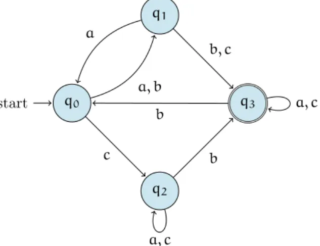
4 Process Calculi 33 4.1 Automatas and Labelled Transition Systems . . . 33
4.2 Sequential and Concurrent Processes . . . 35
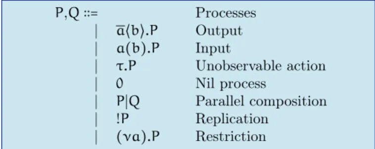
4.3 The π-calculus . . . 35
4.4 The Applied π-calculus . . . 36
4.4.1 ProVerif . . . 37
5 Logic 39 5.1 Logic Clauses . . . 39
5.1.1 Horn Clauses and ProVerif . . . 40
5.2 Theorem Provers and Model Finders . . . 40
6 Black-box Verification Model 42 6.1 The Device . . . 43
6.2 The Malicious User . . . 44
6.3 From m VHDL to the Applied π-calculus . . . 44
6.3.1 Processes . . . 45
6.3.2 Commands . . . 48
6.3.3 Variables, signals and constants . . . 51
6.3.4 Operators . . . 52
6.3.5 Clock . . . 53
6.3.6 The translation procedure . . . 53
7 Looking into the Black Box 56 7.1 From m VHDL to MACE4 . . . 56
7.1.1 Why MACE4 . . . 57
7.1.2 Predicates . . . 57
7.1.3 Functions . . . 59
7.1.4 A semantics for m VHDL . . . 60
7.1.5 The type system . . . 64
8 Conclusion 67 A Examples 69 A.1 A first example: a synchronous LFSR scrambler . . . 69
A.1.1 The VHDL Code . . . 69
A.1.2 π-calculus code . . . 73
A.1.3 ProVerif analysis . . . 76
A.2 An example on a 2-element model . . . 79
A.2.1 The m VHDL code of the CBC . . . 79
A.2.2 The MACE4 input file for the CBC . . . 81
Introduction
Timeo Danaos et dona ferentes.
Publius Vergilius Maro
Nowadays a lot of tasks requiring high-speed processing capabilities are not performed via software anymore, but through hardware: an ad hoc component can be highly optimized for a specific task, possibly with a high degree of parallelism. For this reason ASICs1 and FPGAs2 represent a good solution to address this need.
Speed is not the only reason to perform some operation via hardware, for example cost savings may be achieved by producing a component with specific (but limited) capabilities: such a component, expressely tailored on the task, can be much cheaper than a general purpose processor.
Last but not least, sometimes the need of using hardware derives from security issues as a hardware component is harder to crack or to clone, as doing so requires a sophisticated equipment; it is also an excellent way to store cryptographic keys and provide personal identification.
Hardware programming is largely made through hardware description languages such as VHDL or Verilog: these two languages are equivalent in terms of expressiveness, therefore they share the same verification needs.
The particular need addressed in the present work is the one of ensuring secrecy of confidential data, so that we can be sure that data stored in a circuit will not flow outside: the challenge is to verify these secrecy properties not on the circuit but directly on VHDL code, formally.
We are therefore applying formal methods at the code level, as we are aiming at verifying what is actually going to be turned into hardware.
We propose two different methods: one is based on the black-box verification principles, the other one represents the white-box alternative — whenever applicable, as in some cases we may not have the inner details of how a component is made, but only its specifications.
The remainder of this section is dedicated to outlining the structure of this thesis.
1. Introduction It is not possible to understand the verification approach to be performed on hardware without first addressing both the concept of modelling digital circuits and the topic of formal methods from a broader perspective.
1ASIC stands for Application-Specific Circuit. 2FPGA stands for Field-Programmable Gate-Array.
For this reason the present chapter is divided into three sections: the first one discusses the general ideas of modelling digital circuits, the second one aims at giving a reasonably complete overview of the state of the art in formal methods, with special care towards what is relevant to verification of hardware and software, and finally the third one outlines the approach that has been followed to apply this wealth of techniques to VHDL.
2. Circuit Synthesis through HDL In this chapter we aim at giving a general overview of VHDL and its features, in particular those which are relevant to this work. This will lead to the definition of a subset of the language we will be referring to.
3. Security and Protocol Verification Security is an area which comprises many different topics: in chapter 3 we will try to go quickly through the most important aspects of security, and focus our attention on areas that are most relevant to the scope of this thesis, in particular what concerns protocol verification.
The model, which underlies the analysis techniques we propose, is in fact the one of protocol verification, as an electronic device may be seen as the implementation of a communication protocol, where the agents can send and receive “messages” by means of the accessible terminals; as we are interested in security properties, protocol verification is a mature area from which we can draw ideas and tools. Protocol verifiers will also be presented, with special care to ProVerif.
4. Process Calculi In order to use protocol verification techniques, it is useful to give an overview of process calculi, as protocols are usually modelled as communicating processes. Likewise, we will be modelling electronic components as processes.
5. Logic An understanding of logic is also needed (in particular for what concerns Horn clauses), as we will verify some properties through some tools that process logic clauses as input, such as theorem provers and model finders.
6. Black-box Verification Model As we have already hinted, we will be proposing two different verification methods. The first one sees some subcomponents as black boxes, assuming they are working according to their specifications, and aims at verifying that there is no weakness introduced by the way we have interconnected these subcomponents.
7. Looking into the Black Box The second verification method is applicable if the description of a subcomponent is available: in addition to what we were able to prove with the black-box verification model, we can prove whether this component implements its specification.
8. From VHDL to π-calculus To put all of these ideas into practice we need to translate the VHDL code into a format, which is understandable by the tools we are using. We will be using a protocol verifier — ProVerif — for the black-box verification model, therefore we have to provide it with a π-calculus model of the hardware we aim at analysing. This analysis tells us whether the model we have provided leaks sensitive data.
9. From VHDL to MACE4 For the white-box verification model, we will be using a model finder — MACE4 — that inputs logic clauses. The result of this analysis shows which terminals or wires must not be accessible to a malicious user: accessing these terminals or wires would result in compromising the confidentiality of the data we want to keep secret.
10. Results and Conclusion Finally we conclude by summarizing briefly the work done and the results obtained.
1.1
Modelling Digital Systems
The complexity of digital system has been constantly increasing in the last decades and nowadays it is not viable to understand (or project) such systems without a fair level of abstraction.
This has changed deeply the way electronic systems are designed, as a bottom-up methodology is not feasi-ble, and this older paradigm has been replaced by a top-down methodology: if we start with a requirement document for the system, we can then design a high-level abstraction of the system that complies with the requirements; this abstract structure can then be decomposed into interacting subcomponents and this can be repeated iteratively, until we eventually get to the very bottom-level of transistor design — although normally the process descends down to the level of ready-made primitive components, which are made available to designers through specific component libraries.
Each subsystem can be designed independently of others, and this gives benefits in terms of workload sharing within a team and allows a designer to focus on one part of the system at a time.
The designer can think in terms of a model, abstracting away from tedious and irrelevant details: this implies that a system can be modelled in different ways, depending on what the details are relevant in a given context.
There are a number of good reasons for having models of a system [Ash08]:
• the use of a formal model to communicate requirements makes sure that all requirements are precisely identifiable, in a way that does not leave room for disagreement between customers and developers. Besides, a model clearly states what is required and what can be developed in different ways — what is not in the model is left to the designer’s freedom of choice;
• a formal model also helps a user to understand the functions of a system: as a designer cannot foresee all of the possible ways a system can be used, providing a model of the system itself enables a user to check if it is going to work in the context of interest;
• a model enables developers to test the system they are building through simulation. This helps making sure that the high-level abstraction of the system behaves in the same way as we descend in the design hierarchy, one level of abstraction after the other. These same tests may be used later on the physical circuit, to check that the results are comparable to the simulation;
• having a model of the system is what underlies formal verification of the correctness of a design. We will not get into too much detail here, as we will tbe talking extensively of formal verification techniques in the following section 1.2;
• there are tools that can sythesize circuits automatically starting from a model of the system to be developed: an engineer can focus on developing a good model, the tools will take care of turning it into a manufacturable layout.
System models can be categorized into three domains: the functional domain is concerned with the oper-ations a system can perform and can be seen as the most abstract one, as it does not give any indication on how a function is implemented; the structural domain is concerned with the actual composition of the system, in terms of interconnected components; finally the geometric domain deals with the physical system layout.
Each of these domains is divided into different levels of abstractions — see figure 1.1.
We will be talking more precisely about these topics in chapter 2, with the perspective of hardware description languages in mind.
Functional representation Structural representation Geometrical representation Systems Algorithms Boolean expressions Processor Memory Switch Register transfer Circuit Layout planning Cells Mask geometries
Figure 1.1: Design levels. [GK83]
1.2
Formal Methods
As computers are becoming essential to everyday’s life, and also embedded systems are a constant pres-ence, nowadays we rely heavily on the services provided by electronic devices. This has led to a strong increment in the importance of applying formal methods: the goal is to deliver dependable systems in an effective manner.
From a more general perspective we can see that there are a lot of complex application where some properties represent critical features, and therefore they have to be enforced by any means.
The very founders of computer science, people like Turing and von Neumann, had also some idea of software verification in mind, and this concept has been cropping up more and more often, until technical advances made it feasible: the computational power that has been gained over the years has made formal techniques available and usable for actual applications, overcoming all of those limitations that used to keep them relegated in a purely theoretical world, preventing them from being effectively used outside of it.
This breathed new life into the development of formal methods and gave an impulse that has brought to a whole new set of theories in the field. And all of this is still in fieri.
People have different misconceptions about formal methods. In the nineties Hall [Hal90] gave a list of 7 myths about formal methods, followed a few years later by another 7-myth list by Bowen and Hinchey [BH95a]: nowadays the situation is somehow better from this point of view, although some myths seem to last. [BH06]
For this reason we provide a visual synthesis of the aforementioned articles in figure 1.2.
When verifying a system, the properties that are to be sought vary depending on the purpose of the system. What we usually deal with is:
Myths of Formal Methods guarantee that software is perfect fallible very helpful in finding bugs early can nearly eliminate some classes of errors all about program proving all about specifi-cation only useful for safety-critical systems make you think very hard about what you do useful for almost any application increase develop-ment cost can de-crease develop-ment cost require highly trained math-ematicians only for some things mathematics for specifica-tions is easy programs are harder to read than spec-ifications not used on real, large-scale projects being successfully used in industry unacceptable to users help users understand what they are getting delay the development process better cost- and time-estimation is needed can help save time lack tools many tools available continuous develop-ment of new tools replace traditional design methods sometimes they are overkill integrate traditional design methods apply to software only apply to hardware design as well unnecessary required by some standards highly rec-ommended when cor-rectness is of concern unsupported backed by a large community formal-methodists use only this
applied where needed
Figure 1.2: 14 myths of formal methods (on dark background) and corresponding facts (on light back-ground). [Hal90; BH95a]
• availability — services provided by a system are accessible in time;
• reliability — a system is not subject to failures;
• safety — a system is not source of hazards, risks or damage to people, things or environment;
• security — a system is not vulnerable to intrusion or leaking sensitive information.
Failures in different kinds of systems lead to different consequences: for example safety-critical systems (or life-critical systems), such as flight control systems, must have no flaws, as this may lead to a plane crash.
A failure in a mission-critical system, such as a navigation control system or a flash memory in a core position, is less serious in the sense that it costs no lives, but it may cause a mission to abort.
Sometimes people talk about business-critical systems (a bank accounting platform is such as system): a failure in this case may lead to a considerable loss of money.
These are all settings where application of formal techniques is not only one desirable optional step in the development process, but a required guarantee that allows users to trust a system.
In the past we can find some bugs which led to epic failures, that would have been avoided if appropriate formal verification had been carried out on those projects.
Two really expensive bugs are worth mentioning:
• the Ariane 5 rocket exploded on its maiden launch after only 37 seconds: the reason was a 64-bit floating-point value being converted to a 16-bit signed integer. The estimated loss is around half a billion dollars [Nus97];
• the Pentium processor, released in 1994, had a bug in the floating-point unit and was returning wrong results for some computations. It turned out that five entries were missing from the look-up table that was needed by the algorithm: Intel was prepared to face a cost of 475 million dollars to recall and substitute the bugged chips [Cip95; Wil97].
Software and hardware development can benefit from extensive use of formal methods, as they improve the quality of the software being developed3: what we can obtain is a product which is correct by design
or at least proven to be correct, rather than tested or simulated to be correct.
The difference is crucial, as testing can never make sure that the result obtained at the end of the development process complies with what was originally asked by the client, but can only show that in some chosen settings the given requirements are satisfied: if a bug is found we can only state that the system has a problem to be fixed, nothing more; in E.W.Dijkstra’s words, “testing shows the presence, not the absence of bugs”4. [BR70; Dij72]
Conversely formal methods can prove correctness by analysing the specification of a product, determining which properties it satisfies and what other properties it does not, thus deducing whether in some setting some of the requirements cannot be met: either we find a bug or we state that the system is not affected by any bug with respect to that specification.
Sometimes the analysis performed via formal methods is referred to as static analysis, as it does not require the execution of a piece of code or producing a working prototype. Conversely testing is sometimes referred to as dynamic analysis.
An approach to formal analysis is to build a system, which implements a specification satisfying the requirements we are interested in, and then proving that the resulting implementation is a refinement of the initial specification. The compliance of an implementation with the corresponding specification is usually shown via a so-called refinement calculus. Still we must be aware that a formally verified system is just as good as its specification, so special care is required when defining a specification.
An alternative approach, that can be applied to systems built without using formal methods, is to verify properties on a model of the real system, that we will treat as its specification: again, the results are just as good as this specification.
The fact that the results are weighted against the appropriateness of the specification is one of the reason why in any case formal development, though overcoming the limitations of testing, still requires it5: errors
may derive from a wrong or poor specifications.
3As in any other human — and thus error-prone — activity, absolute perfection is not something realistically achievable.
Nonetheless formal methods help filling the gap: we could say that “they work largely by making you think very hard about the system you propose to build”. [Hal90]
4Incidentally, as an indication on the historical interest on formal methods, it is worth noticing that this statement
dates back to 1969 and was said during a conference on software engineering techniques sponsored by the NATO Science Committee: software specification and correctness were among the topics it addressed. [BR70]
Moreover, sometimes a human error can affect the verification procedure itself, possibly producing wrong results: again, formal methods represent a more rigorous technique than the traditional programming paradigms — therefore they can lead to increasing confidence in system integrity and performance when applied correctly, as their rigour helps reducing (though not eliminating) human error6 — and are
par-ticularly suitable for some7 applications, but that does not mean that they guarantee the development of bug-free products.
Besides improving overall product quality, the use of formal methods may be more cost-effective than traditional methods. One reason is because it helps spotting bugs in earlier stages of the development process (when they are cheaper to correct): the use of formal methods in industry is entering the develop-ment routine, and this allows some flaws to be uncovered well before a product undergoes testing (some examples of application of formal methods in industry may be found in a recent survey by Woodcock et al. [Woo+09]).
Another cost-saving feature that derives from the use of formal methods is that components can be reused: it is really easy to reuse formally developed components as they have a formal specification that can be quickly integrated as a black box into a new specification; besides, it is not simply a black box, it is a verified black box. A special kind of reuse is when a system is ported to a different architecture. From a maintenance perspective, a formally developed system generally features a cleaner architecture, therefore maintenance can be more efficient.
Formal methods can be used in any and all of the steps of the development process, so they can be effective to help maintaining high-quality standards throughout the evolution of a product.
They also provide guidelines about how things should be done, sometimes drawing a line between what is considered to be good development practice (e.g. code that can be verified8, that makes extensive
use of assertions9,10 and of any other device conceived to enforce correctness, that is available in the programming language being used) and what is to be avoided.
Formal methods is a mature area, but nonetheless it is still very attractive and vital for research, in terms of number of researchers, publications and funding. [Woo+09]
1.2.1
Product Development
The development of a product begins with the specification of the requirements it must comply with: these are properties which abstract from the actual implementation and the product can be engineered as preferred, as long as it meets all of the requirements.
It is crucial though that requirements are expressed in a complete and unambiguous way, so that both the designer and the user have the same understanding of what requirements the product is expected to comply with.
Requirement engineering comprises all of the steps that concur to the definition of the specification. According to Nuseibeh and Easterbrook [NE00] these steps are the following:
6Formal methods are no panacea, the more realistic goal is expressed in the manifesto of the Verified Software Initiative:
“We envision a world in which computer programmers make no more mistakes than other professionals.” [Hoa+09]
7Traditional development methods may turn out to be more cost-effective for some non-critical applications, sometimes
it is the other way around.
8This is actually no big limitation to a programmer’s freedom, as programming theory now covers many aspects of
modern programming languages.
9In Microsoft Office there is an assertion about every tenth line of code (dropping to one every hundredth line in
Windows). Nonetheless their existence is mostly due to testing purpose, rather than for proving correctness or the verifying if the program implementation refines its specification — but this programming practice is propedeutical to this goal: assertion may enable a verifying compiler to verify assertion at compile time, rather than at runtime. [Hoa02; BH06]
• eliciting requirements;
• modelling and analysing requirements;
• communicating requirements;
• agreeing requirements;
• evolving requirements.
Having a high-level specification to comply with simplifies the task of organising the architectural struc-ture of their components.
The next step is the implementation level and we can use formal methods to verify the correctness of the code that has been written: formal methods aim at proving that, withstanding certain conditions, a verified implementation satisfies the requirements outlined in the specification.
Developers can also avail of code generators that provide verified code, which is directly derived from formal models.
Once we have a verified product, we can use formal methods for its maintenance and evolution to keep everything working at the verified level.
1.2.2
Tool Support
Tool support is fundamental for the successful application of formal method techniques.
Some 20 years ago verification was performed through syntax and type-checkers (this is for example the case of the IBM CICS transaction processing system [HK91], first major technical achievement in this area), or also done by hand (yet in a successful way, as testified by the Mondex project, featuring a 200-page proof [Woo+08]).
Nowadays we have to face larger projects and we need (and we can avail of) more powerful tools, either completely automated or requiring human interaction.
Thanks to advances in the theory, we can count on automated theorem provers (in particular for first-order logic), proof assistants, SAT11 and SMT12 solvers, model finders, model checkers, protocol verifiers
and so on, each tool with its own advantages and limitations.
The research community keeps on developing new tools — as well as maintainig and improving the existent ones — and some commercial tools are also available (a well-known example is SCADE by Esterel Technologies [Ber08], used for example by Airbus in the last decade), nevertheless some more work is still required in order to improve usability of these tools and foster industrial application to embrace a larger number of projects.
In the present work only some of the tools mentioned above have been used, and their features will be presented later on.
1.3
Static Analysis of Circuits
The previous section was meant to make the point, that from a general perspective there are several advantages of static analysis compared to dynamic analysis.
11In complexity theory the satisfiability problem is usually referred to as SAT. 12Satisfiability Modulo Theories — this is an extension of the SAT problem.
Let us now think of what this means in the hardware world: most of the above considerations still apply (with hardware programming the boundary between electronics and computer science is blurred), but there are some concepts which have particularly relevant implications for hardware designers.
If there is a software bug usually a patch is released, and the product is fixed after the patch has been applied (in the best case, i.e. unless the product has been critically compromised because of that bug). Hardware components are not always fixable. For example let us imagine we want to implement in hardware a function and we design an ad hoc integrated circuit: what is the cost of discovering a bug after all the masks have been produced? Or even worse, what is the price of having to replace a component, after it has already been produced and, possibly, deployed? It is hard to quantify, but a quite accurate answer may be “too high” — let us think again of the infamous Pentium FDIV bug. [Cip95; Wil97] The advantage of static analysis is that it does not require that a component is actually implemented to analyse it: this is potentially a great cost-saving feature, as bugs can be detected at the very first stages of development, so this is particularly important if the component is hardware.
Though formal methods cannot eliminate hardware failures, they become important in verifying that error-handling procedures are implemented correctly.
Besides this, they can also help preventing these failures: a reasonable specification may require that the normal functioning of a system does not wear out a component, and we can prove whether the way we have implemented that system satisfies this crucial requirement. An example may be a flash memory controller, that should ideally implement some wear-levelling algorithm, so that the memory areas are all evenly used.
Another feature that becomes particularly important when referred to hardware is the improvement towards component reusability: the process of creating masks for the mass production of ASICs is an expensive one, so it is a good thing being able to reuse a well-designed component. The advantage is that once we interconnect verified components, we do not have to worry about verifying their inner behaviour, but just make sure that we have connected them in a sound way.
A subtle property that requires a formal analysis to be proven is security. we can never be sure that there exists no input (or sequence of inputs) to a system that causes an undesirable behaviour (such as leaking data, that was not to be disclosed) unless we prove this formally.
1.3.1
Static Analysis of Circuits for Security
There are many factors that concur to the concept of security, and their relevance changes depending on the area of interest. Just to mention a few examples, security can mean anonimity in some applications while in some other can be non-repudation, sometimes security is secrecy, sometimes integrity.
This looks like a list of buzz-words — well, actually it kind of is — but it is just a short way to make the point, that we keep quite a lot of different things under the big hat of security: we will be talking more in detail about concepts relating to security in chapter 3.
For these reasons there are different related properties that we may want to prove on a security-oriented circuit, and obviously we are not claiming we are addressing all of them: the aim of this work is rather specific, i.e. tackling the problem of proving secrecy properties on circuits, that are described by VHDL code.
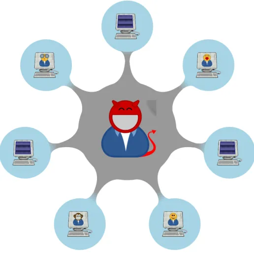
More specifically our goal is to develop a methodology to ensure that a circuit will not reveal some confidential data it contains, regardless of the way it is used — i.e. even if given to a malicious user, who
can send it whatever input he wants, there is no way to make the circuit output confidential data. The challenge is to find a way to prove this directly from the VHDL code that describes it; there is no literature that addresses specifically this task, but something has been written on other topics that are somehow related to our goal, in particular:
• type systems to analyse information flows: type systems are a powerful tool to ensure that a system is treating data appropriately, as they aim at verifying that coherence is maintained throughout the system: if a system typechecks, it cannot be the case that a piece of data of a certain type is in a position where data of that type is not supposed to be. In particular type systems can be used to control information flows: there is some work oriented towards security issues in data flows [VIS96; LV05];
• protocol verification: this topic focusses on security protocols, an area where the verification ap-proach can use typing rules to prove secrecy properties on protocols [Aba99]. These rules are to be applied on a model of the protocol expressed as concurrent processes: if it typechecks we can be confident that no confidential information will be disclosed because of a flaw in the protocol. In general all the wealth of work done in the area of protocol verification is an important resource to reach the goal we have in mind, and will be discussed extensively in chapter 3;
• information flow analysis on VHDL code: this topic addresses some of the issues we are interested in, as information flow analysis can be used to track the path of data within a circuit, and in particular the path of confidential data. This can be done by analysing the VHDL that describes a system: in [TNN05] we can find an analysis technique of this kind, that results in a transitive non-directed graph from which we can derive pretty accurate results on data flows that interest the circuit. In addition to “simply” tracking the flow of data, we want a technique that can be aware of the subtle mathematical properties of the functions that are used for security applications (for example the xor function): results in this area offer a good starting point to move towards our goal;
• checking safety properties on VHDL code: safety properties and security properties have quite a lot in common from a verification perspective, as they both require an effective way of modelling the system to be analysed. We can draw interesting ideas from the work done in this area [Hym02; Hym04], as the way VHDL code is modelled to prove safety properties can be readapted to serve our purpose, in particular for what concerns giving a semantics to VHDL — without forgetting some older work, not safety-related, that is specifically addressing the task of giving an operational semantics to VHDL [Goo95; TE01].
The remainder of this section is dedicated to giving a general understanding of the problem we are addressing, in terms of how the circuits we are dealing with are made and of how they can be modelled. The technical details are postponed to the relevant chapters.
Working Hypotheses
The working hypotheses underlying this work are the following:
• the only accessible terminals of the circuit are declared a priori, a malicious user cannot access any other part of it;
surges, etc.) can help a malicious user break the system13, but we assume that no attack exploiting
such weaknesses can be successfully performed on the system;
• there may be some blocks which are assumed to work perfectly (i.e. their real implementation corresponds to their specification, so they behave exactly how they are supposed to): these are the black boxes in the black-box verification model.
It is worth spending a few words discussing the last hypothesis: in real world implementations circuits are very often implemented by assembling IP blocks14: as the VHDL code that describes these blocks is
usually unknown (IP blocks are normally offered as netlists) the designer has to trust the vendor that the provided block has been verified and works according to its specification.
Thus an IP block is nothing but a black box to the designer: he only knows what output corresponds to a given input.
This development methodology, though avoiding errors regarding what is implemented in IP blocks (in line of principle), is still prone to design errors when assembling these blocks: a final verification step can make sure that this has not happened.
Data, Channels and Functions
Within a circuit we can distinguish between data that can be publicly known and data that need to be strictly confidential: a circuit leaking this second type of data has an unacceptable flaw.
During the normal operation of the circuit, we have flows of both types of data and we have to make sure that confidential data is never treated as public data — though we do not mind if public data is treated as confidential data.
Attention must be paid to what kind of data is input to the circuit and, especially, to what kind of data is output by the circuit: we must be able to ensure that secret data is adequately protected and prevented from being diffused outside the circuit.
This task is not an easy one, as we need to track each piece of data and follow accurately its path and its interactions with other pieces of data, as well as taking into account what the effects of function applications are.
In a circuit data are transported by means of wires, and can be input or output to terminals: we will treat all these in the same way, and to us they will be simply channels.
We divide the possible channels through which data is flowing into two kinds: some channels that are suitable to transport both types of data and some other channels that must not transport secret data, as they do not preserve the secrecy of data flowing in.
A malicious user has access to these latter channels.
We can further distinguish channels into three types: input channels, output channels, internal channels:
• the malicious user can write on input channels;
• the malicious user can read from output channels;
• the malicious user cannot do anything on internal channels, as he cannot access them.
13Attacks of this kind are called side-channel attacks — for more information on these attacks one can refer to [Sta10]
and [Sal10].
14Intellectual Property blocks are reusable components — logic, cell or chip layout design — that are used increasingly
We can imagine that these channels are interconnected through particular gates: these gates are the functions that are applied to data.
Depending on the function, the type of a piece of data can eventually be changed, or different pieces of data are combined into a single piece (so the data type can potentially change in this case as well). After merging all of these notions together we can build a model of the system we want to verify: a suitable way to prove the desired properties in this model can be a type system — if a system can be proved to be well-typed, we have the formal proof that it fulfils the security requirements it was demanded to.
Circuit Synthesis through HDL
A good scientist is a person with original ideas. A good engineer is a person who makes a design that works with as few original ideas as possible. There are no prima donnas in engineering.
Freeman Dyson
Technology advancements have influenced the way hardware is designed: enough computational power has become available since the eighties and this has led to the implementation of new software tools to speed up (and improve) the task of hardware design.
Another reason why such new tools were needed was the crisis of VLSI design at the beginning of the eighties: circuits were becoming smaller and smaller and at the same time they were made of an increasing number of subcomponents (nowadays it is no wonder having chip with millions of transistors, but back in the eighties it was quite a great achievement), thus designing such complex systems by hand was becoming an increasingly challenging task, both in terms of avoiding errors due the large scale of the systems and for what concerns meeting the deadlines1. As a result of the adoption of these new tools, the time to market has reduced dramatically in comparison with what was achievable with the techniques based on designing schematics used till that moment, as the process was essentially a graphic one (the only tools available were essentially geometric software, and placement and routing tools started to be developed since the mid-seventies).
EDA2tools have been the result of this combination of technology push and market pull.
They have the ability to synthesize circuits automatically, starting from a description in a suitable format: in the early eighties hardware description languages (HDL) made their first appearance on the electronic-design scene, and were meant to provide a precise description of the hardware to be implemented. HDLs are general purpose and can be used to describe very complex systems as well as simple circuits made of just a few gates.
The description of a system can be on different levels of detail (see figure 1.1) — here is an example where a binary adder is seen at some of the different possible levels [Rot98]:
1In a highly competitive environment as the electronic market, products have to be built as quickly as possible and in a
cost-effective way — time is a factor just as important as cost.
2EDA stands for Electronic Design Automation.
Transistor Gate RTL Architecture Algorithm System concept
Figure 2.1: Top-down design. [Smi98]
• at the behavioural level (on the functional representation axis) it is described by a function that adds to binary numbers (no implemenation is given);
• at the data flow level (still on the functional representation axis, but on a lower level) the description is given by the logic equations for the adder;
• at the structural level (on the structural representation axis) the adder is specified by the gates it is made of and their interconnections.
Top-down design methodologies can be effectively adopted thanks to these tools, and allow designers to work at higher levels, focussing on the functionalities they want to implement, rather than on the logic-and transistor-level design (see figure 2.1): this is a way to meet the market needs, demlogic-anding shorter development cycles and increasingly complex capabilities.
This is also the only reasonable way to design SoCs3, where the number of gates involved is commonly over one million gates — this has made possible for very complex systems to be synthesized on a chip, but also means that a schematic entry tool, besides being extremely error-prone for large-scale projects, is not a viable design method, as it would not be cost-effective, and extremely tedious and time-consuming. The full description of a system in HDL results in a design that is portable among different EDA tools and independent of any particular silicon vendor’s manufacturing technology.
The synthesis process comprises alternating steps of translation and optimization4, that descend one
abstraction level after the other until the very bottom level: this procedure extracts a netlist from a high-level description.
The behaviour of a component can be simulated and the result does not depend on the level of abstraction by which it is modeled — the simulation can be based on its HDL description as well as on its gate-level representation: this yields the same results.
3SoC stands for System on a Chip.
4There may be different kind of optimization that lead to different results: for example optimizing in order to achieve
Specify Document Capture Verify Implement HDL code
Test bench development Synthesis
Layout
Functional Simulation
Timing Simulation ASIC vendor for fabrication
Specific to ASIC design
Figure 2.2: Design process. [PT97; Cha99]
Being able to simulate hardware has been a major achievement: the first, obvious reason is that it allows to detect bugs at early stages, rather than having to wait for the first prototype to be tested.
A second reason is that different design alternatives can be compared quickly by simulation.
A third reason is that it enables the designer to perform the so-called fault simulation, where typical manufacturing faults are injected into the model: when the final design is delivered to the manufacturer, the designer provides a set of test vectors which are to be used to test the final product, and the fault simulation aims at making sure that these test vectors are effective in detecting the most common manufacturing faults.
The design process can be divided into 5 macrosteps (see figure 2.2): the first one is the specification of the system that has to be designed, when the performance and interface requirements are formalized, without going down to implementation details; the second step is capturing the design, when the details of the system and its components are expressed through a computer-based design system, both as schematics and as HDL descriptions.
The following steps are interconnected: the implementation step starts with the synthesis from the HDL description, and this allows the verification of the design to start — test benches5 are applied to the
captured design, through functional simulation. Once this has been done, it is possible to proceed with
5A test bench is a performance specification for the circuit, that have to be developed during the design specification
the implementation and extract the layout of the synthesized system: after this the designer has some more verification to do, as it is possible to do the timing simulation.
If everything works as expected, i.e. the system complies with its specification, the layout can enter the manufacturing phase.
A documentation can be extracted from the specification of the circuit (usually before the end of the design process); being able to document adequately electronic system has been the reason pushing the project that led to VHDL (see the following section 2.1).
Summarizing, the advantages of this design approach are [Smi98]:
• increased productivity yields shorter development cycles with more product features and reduced time to market;
• reduced non-recurring engineering costs;
• possibility to reuse existing designs;
• increased flexibility to design changes;
• faster exploration of alternative architectures;
• faster exploration of alternative technology libraries;
• use of synthesis to rapidly sweep the design space of area and timing, and to automatically generate testable circuits;
• better and easier design auditing and verification.
There are two accepted industry standard HDL, namely VHDL and Verilog.
Although VHDL became a standard before Verilog did, they have the same expressive power6, so which
one is to be used is actually a matter of a designer’s taste (or training): as we have already stated in the very beginning, we will be considering only VHDL, but whatever applies to VHDL is going to be applicable also to Verilog.
2.1
VHDL
VHDL stands for VHSIC7 Hardware Description Language [Iee], and was a result of the VHSIC program, started in 1980 by the American Department of Defence: the purpose of this program was to make circuit design self-documenting, and it soon became clear that a standard HDL had to be provided to the subcontractors if this goal was to be achieved — this HDL had to be used to describe the structure and function of the designed systems and their components8.
The development of VHDL began in 1983 with a joint effort of IBM, Texas Instruments and Intermetrics, under contract with the Department of Defence: this led to the definition of VHDL, that was later accepted from IEEE in 1987 as IEEE Standard 1076.
The 1987 standard is known as VHDL-87, later superseded by the 1993 and 2002 versions, known respec-tively as VHDL-93 and VHDL-2002, and by the current version that has been approved in 2008, known as VDHL-2008.
6Some tools translating from VHDL to Verilog are also available, such as Synapticad V2V. 7VHSIC stands for Very High Speed Integrated Circuit.
8The design of the F-22 tactical fighter, started in 1986, was one of the first major government project, where it was
Thus VHDL is a language that has been designed and optimised to describe digital systems and as such combines features of [PT97]:
• a simulation modelling language: the behaviour of electronic components can be modelled to a very precise level of detail through VHDL, and this can be used for systems of any size, ranging to simple circuits with only a few logic gates to complex ASICs and processors. Aspects that can be modelled include electrical aspects (rise and fall times, delays, and functional operation), so that it is possible to simulate the system to a high degree of precision;
• a design entry language: complex behavioural specification can be captured by VHDL, mixing low-level statements inherent to hardware with higher-level blocks, that remind conventional pro-gramming languages (in comparison with most propro-gramming languages, there is the added benefit of the possibility to describe concurrent statements — this is one big difference between hardware and software programming);
• a verification language: VHDL allows to capture test benches, and thus allows the designer to verify that the circuit behaviour complies with the requirements, both functional and temporal;
• a netlist language: VHDL can describe a circuit both at a high-level and at a lower level, and for this latter capability it can be used as a netlist language — for example it may be needed by tools that need to communicate at a low-level.
Hardware is represented in VHDL by means of a composition of building blocks, which are referred to as design entities: a design entity is a portion of the design, that has well-defined input and outputs, and that performs a precise operation.
It is defined by an entity declaration and a corresponding architectural body : the former defines the interface between the entity itself and the surrounding environment, the latter gives the actual description of what is contained in the entity, in particular it defines what relationship links inputs and outputs. For each entity it is possible to have different architectural bodies, that represent the possible alternative implementations to instantiate that entity.
Configurations define the way entities are composed together into a design, by means of a configuration declaration.
An entity can be seen as being hierarchally organised into blocks, whereas the entity itself is the top-level block, which is made out of internal blocks (nothing but blocks of statements): sometimes the entity is referred to as external block, as it can be collected in a library and be used in different other designs. A block of statements contains statements describing the internal organization and/or the operation of the block; the statements in a block execute concurrently and asynchronously.
Architecture bodies can contain also processes, which are a collection of actions that are to be executed sequentially (sequential statements).
In VHDL we have the familiar constructs of function and procedure declaration: as usual, a function is an expression that returns a value (there is the distinction between pure functions, that return a value which is deterministically dependent on the function arguments, and impure functions, that may return different values everytime they are called, even if they are passed the same arguments), whereas a procedure call is a statement.
Besides this behavioural description, it is possible to provide a structural description of an entity, by giving the port mappings that describe the connections among its subcomponents.
It is customary to use a mix of structural and behavioural descriptions, that results in a hybrid model. VHDL is a large language and we do not need to take into account all of the features it offers, so — as customary in formal work regarding VHDL [Goo95; Hym02; Hym04; TNN05] — we will restrict ourselves to a subset of the available language constructs (which is also roughly the subset commonly used in real-world applications).
We will dedicate the remainder of this section to present the features of VHDL in finer detail, i.e. to the extent of what is necessary to develop an utility that parses actual VHDL9.
We will be using the following notational conventions:
• reserved words are in typewriter font: reserved_word;
• syntactic categories are in italic sans serif: syntactic_category;
• an optional item is enclosed within square brackets: [optional_element];
• a comma-separated list of items, all of the kind kind_of_item, is written by enclosing such kind within angle brackets: ⟨kind_of_item⟩.
2.1.1
Lexical Elements
VHDL description are expressed as text files, that can contain any character from the ISO-8859-1 char-acter set10.
Identifiers A valid VHDL identifier must respect the following rules11:
• it must only contain alphabetic letters (without diacritics, i.e. from A to Z and from a to z), decimal digits and underscores;
• it must start with an alphabetic letter;
• it must not end with an underscore;
• it must not contain two successive underscores.
Identifiers are not case-sensitive.
Values Values that can be used in a VHDL description are:
• numbers: expressible in decimal format (also in exponential notation) and in an arbitrary base (with an eventual exponent)12;
• characters: a character has to be enclosed in single quotation marks;
• strings: a string has to be enclosed in double quotation marks;
9This section is not meant to be a manual, some of the constructs may be simplified by omitting some optional parts.
For more accurate detail on syntax, refer to the IEEE 1076 standard [Iee] or to one among the following references: [PT97; Rot98; Smi98; Cha99; Coh99; Ash08; Mäd09].
10Only ASCII character were supported in the early days of VHDL-87
11These are actually VHDL basic identifiers: since VHDL-93 extended identifiers are supported and can be any sequence
of characters, enclosed between \ characters.
• bit strings: a bit string is a string containing only binary, octal or hexadecimal digits, which are to be expressed by putting respectively B, O or X before the opening double quotation mark13.
Reserved Words We are not giving an exhaustive list of reserved words, as those which are relevant to the constructs within the scope of this thesis will be presented when each construct is introduced.
Operators VHDL operators include (but are not limited to): not, and, or14, +, -, < and =:
op ∶∶= not ∣ and ∣ or ∣ lnot ∣ land ∣ lxor ∣ + ∣ - ∣ < ∣ = ∣ . . .
Comments Single-line comments are introduced by a double hyphen (--) and comment out the text from there to the end of the line15.
2.1.2
Data Types
The type of data defines the set of values that constants, variables, signals and files16.
VHDL is a strongly typed language and offers many different data types (see figure 2.3): in the present work we will be using only a few of them, described in the remainder of this subsection.
Discrete Types
VHDL offers different discrete types, the ones we will be needing are integers and booleans:
• the integer type corresponds to the range[−2 147 483 647.. + 2 147 483 647]; it is possible to declare a custom type which is a subset of this range, via the reserved word range:
integer_type_definition ∶∶= typetype_name is rangelower_bound toupper_bound
∣ typetype_name is rangeupper_bound downtolower_bound
• the boolean type is a standard type comprising only two values, true and false. It is customary to use an enumerated type instead of booleans, namely the std_logic type, that has 9 possible different logical values and complies with the definitions in the IEEE standard 1164:
0 — strong drive, logic zero;
1 — strong drive, logic one;
X — strong drive, unknown logic value;
L — weak drive, logic zero;
H — weak drive, logic one;
W — weak drive, unknown logic value; ;
Z — high impedance;
U — uninitialized;
- — don’t care;
13VHDL-2008 has also other ways to express bit strings.
14All of these three are overloaded and can intended both as bitwise and as logical operators: in the definition we will
split them, by putting a letter l before the logical operators.
15VHDL-2008 supports multiline comments, enclosed within /* and */. 16These are the different kinds of object that are available in VHDL.
Types
Scalar Access File Composite Protected
Discrete Floating-point Physical Array Record
integer boolean bit std_ulogic severity_level file_open_status file_open_kind character
real time string
boolean_vector
bit_vector
integer_vector
real_vector
time_vector
Figure 2.3: VHDL type classification. [Ash08]
Arrays
An array is a collection of values of the same type; each element in an array is identified by its index17,
which is a scalar value.
Therefore an array is a composite data type, and has to be declared via the reserved word array:
array_type_definition ∶∶= typetype_name is arraydiscrete_range oftype
Individual elements of an array are accessible by postponing (index) to the array name, where index
identifies the position of the desired element in the array.
2.1.3
Expressions, Operations and Assignments
An expression is a combination of constant values, variables and signals, combined by operators. It can be evaluated, by replacing each variable by its current content and doing the maths.
17One-dimensional arrays have their elements identified by a single index, but in general it is possible to have n-dimensional
expression ∶∶=constant∣variable∣signal
∣ op expression∣expression op expression
Objects like constants, variables and signals can be assigned an expression or a value. For constants and variables we have the following declarations:
constant_declaration ∶∶= constantconstant_name :type :=expression
variable_declaration ∶∶= variablevariable_name :type[:= expression]
Constant and variable declarations look very similar. The big hidden difference is that constants are declared in the very beginning and are not allowed to change their contents during the program execution: this difference is actually crucial, as constants are only a conceptual device for the designer, and will disappear at compile-time, when they will be replaced by the value they stand for.
Through an assignment, that is executed at run-time, we can change the contents of a variable:
variable_assignment ∶∶= variable_name :=expression
For the purpose of this work we can think of a signal as the electrical equivalent of a variable, with the difference that the value18 it bears is physically present on a wire or on a pin.
The signal assignment statement is very similar to variable assignment19:
signal_assignment ∶∶= signal_name <=expression
2.1.4
Conditional Statements
VHDL has conditional statements, such as the conventional if statement20, that executes a sequential statement if the condition it depends on is true.
Optionally it can offer one or more alternative codes to be executed if this condition does not hold:
if_statement ∶∶= if condition then sequential_statement
[elsif condition then sequential_statement]
[else sequential_statement]
endif
We will give a definition of sequential statement in subsection 2.1.6.
18More generally a signal can bear a waveform, but for the application we are examining we are always dealing with
a waveform that has constant value between signal assignments — that is the reason why in this casse there is a strong similarity with variables.
19To be precise, coherently with what we say in the preceding footnote, the proper definition should besignal_assignment ∶∶=
signal_name <=waveform[after time_expression], where the expression is substituted by a waveform and a time delay can be specified.
20It also has the case statement and, in VHDL-2008, also the conditional assignment and the selected variable assignment :
2.1.5
Loop Statements
When a sequence of actions has to be repeated, we can avail of loops, such as the while loop21: if a
condition holds at the beginning of the loop, than the sequential statement it contains is executed, and this happens as long as the condition holds.
Obviously, if the condition does not hold when the program is supposed to enter the loop, the loop is skipped:
while_loop ∶∶= while condition loop sequential_statementendif
2.1.6
Sequential and Concurrent Statements
In VHDL we distinguish between sequential and concurrent statements.
Sequential statements are either the constructs that have been presented so far or any sequential compo-sition of sequential statements: the sequential compocompo-sition operator is the colon ; — this is a recursive definition: sequential_statement ∶∶=variable_assignment ∣ signal_assignment ∣ if_statement ∣ while_loop ∣ . . . ∣ sequential_statement;sequential_statement
Concurrent statements are executed in parallel and are instantiated by processes in the entity body:
process_body ∶∶= process [(sensitivity_list)] [is]
process_declarative_item
begin concurrent_statement
end process;
sensitivity_list ∶∶= ⟨signal_name⟩ ∣ all
We may give the following recursive definition for a concurrent statement:
concurrent_statement ∶∶=process_body [concurrent_statement]
2.1.7
Entity Declarations, Architecture Bodies
The first step towards the design of an entity is its declaration, that describes the interface it presents to the system:
entity_declaration ∶∶= entity entity_identifier is
port (port_interface_list)
entity_declarative_item
end [entity] ;
21There are other different kinds of loop that are available in VHDL: we chose to give a definition of the while loop only,
port_interface_list ∶∶= ⟨port_identifier:[port_mode]subtype_indication[:= expression]⟩
port_mode ∶∶= in ∣ out ∣ buffer ∣ inout
Theentity_declarative_itemcontains all type and constant declarations that are to be used in the entity.
To provide a code for an entity, we have to write its architecture body
architecture_body ∶∶= architecture architecture_identifier of entity_identifier is
block_declarative_item
begin concurrent_statement
end [architecture] ;
Theblock_declarative_itemcontains all of the declarations needed by the architecture body.
2.1.8
Structural Descriptions
Once we have coded all of the entities, they have to be instantiated to build a system.
The structure of such a system can be described in terms of subsystems, that are interconnected by signals (and this can go on recursively, referring to the structure of these subsystems). These interconnections are described via the port map statement when the component is instantiated:
component_instantiation ∶∶= entity entity_name [(architecture_identifier)]
port map (port_association_list) ;
port_association_list ∶∶= ⟨[port_name =>]signal_name∣expression∣ open⟩
2.2
m VHDL
m VHDL is the subset of VHDL we will be using: its syntax comprises only the construct that we have mentioned explicitly in the previous section22.
The data types we will be considering are integers, booleans for truth values and a subset of std_logic — i.e.{0, 1, U} — for logical values.
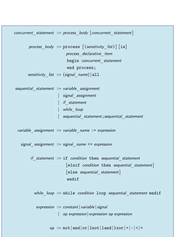
For convenience the syntax needed for concurrent statements in m VHDL is presented in figure 2.4.
concurrent_statement ∶∶=process_body [concurrent_statement]
process_body ∶∶= process [(sensitivity_list)] [is]
process_declarative_item
begin concurrent_statement
end process;
sensitivity_list ∶∶= ⟨signal_name⟩ ∣ all
sequential_statement ∶∶=variable_assignment
∣ signal_assignment
∣ if_statement
∣ while_loop
∣ sequential_statement;sequential_statement
variable_assignment ∶∶=variable_name :=expression
signal_assignment ∶∶=signal_name <=expression
if_statement ∶∶= if condition then sequential_statement
[elsif condition then sequential_statement]
[else sequential_statement]
endif
while_loop ∶∶= while condition loop sequential_statement endif
expression ∶∶=constant∣variable∣signal
∣ op expression∣expression op expression
op ∶∶= not ∣ and ∣ or ∣ lnot ∣ land ∣ lxor ∣ + ∣ - ∣ < ∣ =
Security and Protocol Verification
Security, like correctness, is not an add-on feature.
Andrew S. Tanenbaum
Information security is a problem that is always an actual one, and technological advancements have only changed the nature of the means to be used to secure information: having to deal with electronic information makes it necessary to provide the same tools that were available for pen-and-paper commu-nications, that allowed to authenticate a message (a signature), to keep it confidential (an envelope), to ensure that it was not altered during the delivery process (a seal), and so on.
Such tools are necessary, because communications take place in a hostile environment, where we have adversaries (or attackers) besides legitimate agents and we have to deal with them: in the best-case scenario we are in the presence of a passive adversary, which cannot do much but eavesdrop from an unsecured communication medium; a more worrying scenario is when information security is challenged by an active adversary, who can also inject, modify or delete information from an unsecured communication medium.
Some of the necessary support to achieve the goals set by information security issues can be provided by cryptography, in the form of digital signatures to substitute hand-written signatures and authenticate a message, encrypting algorithms to make up for envelopes and provide confidentiality, techniques to ensure data integrity to replace seals, and so on.
This can be used in an electronic communication protocol, in order to preserve security properties of data being transferred: the scenario we are dealing with is a communication where two entities interact through a channel, which can be either secure or unsecured, depending on what an adversary can do with it.
The communicating parties are the entities that access the communication channel, and the legitimate agents are usually referred to as the sender and the receiver, depending on the direction of the information flow.
3.1
Cryptography
Cryptography is the study of mathematical techniques related to aspects of information security such as confidentiality, data integrity, authentication, and non repudiation:
Security primitives Unkeyed Simmetric-key Public-key Hash functions One-way permutations Random sequences Simmetric-key ciphers
Keyed hash functions
Signatures Pseudorandom sequences Identification primitives Public-key ciphers Signatures Identification primitives Block ciphers Stream ciphers
Figure 3.1: Security primitives. [MVO96]
• the aim of confidentiality is to maintain secrecy of data, so that it can be disclosed only to those who are entitled to access it;
• we are interested in making sure that transmitted/received data is not subject to any kind of alteration from a third party: data integrity is the service that we require to take care of this;
• electronic information can be duplicated easily and effortlessly: for this reason we need a way to identify data (data origin authentication) and those who manipulate it (entity authentication);
• finally we are interested in non-repudiation: this means that an entity cannot deny an action or a commitment.
The building blocks of cryptography are sometimes called primitives, and are shown in figure 3.1.
3.1.1
One-way Functions
Not all invertible functions are equal from a cryptographic perspective: an important role in cryptography is played by those which are straight-forward to compute, but for which it is computationally infeasible to compute the inverse function.
Such functions are usually referred to as one-way functions — one of the best known examples is the exponentiation over integers: there exists no efficient algorithm to compute discrete logarithm (yet).
A particular class of one-way functions which is often used in cryptography is that of hash functions: a hash function maps a string of arbitrary length to fixed-length binary string (hash), which has the property that it is infeasible to find two different inputs that have the same hash (colliding inputs), besides being efficient from a computational perspective.
Trapdoor one-way functions constitute a particular class of one-way functions, that have the property of being invertible in a computationally feasible way if some extra information (called trapdoor information) is available.
Finally another kind of functions we will be talking about are involutions, which are function which enjoy the property of being their own inverses.
3.1.2
Encryption Schemes
With an encryption scheme we aim at creating bijections between the message space M , containing plaintexts, and the cyphertext space C , containing cyphertexts: they both contain strings, formed of symbols from an alphabetAM orAC respectively — genereally speaking they can be different, but usually
they are simply the alphabetA= {0, 1}.
Encryption and decryption transformations (Dd and Ee) are bijections which are uniquely determined
by keys d, e taken from the key space K , and they relate elements from the spaces M and C .
The key space has to be large enough to prevent an adversary to find the keys that have been used, thus identifying the encryption and decryption transformations, through exhaustive search.
An encryption scheme consists of two corresponding sets of encryption and decryption transformations, such that for every encryption key e there exists a decryption key d that allows to recover any message mthat has been encrypted:
∀m, e ∃d ● Dd(Ee(m)) = m
Kerckhoffs’s desiderata date back to 1883, but are still valid today (with minor changes) and set require-ments that should be satisfied by an encryption scheme:
1. the system should be, if not theoretically unbreakable1, unbreakable in practice;
2. compromise of the system details should not inconvenience the correspondents;
3. the key should be rememberable without notes and easily changed;
4. the cryptogram should be transmissible by telegraph;
5. the encryption apparatus should be portable and operable by a single person;
6. the system should be easy, requiring neither the knowledge of a long list of rules nor mental strain.
Here is a non-exhaustive list of the most common attacks that can be mounted against an encryption scheme:
• a ciphertext-only attack is one where the adversary tries to deduce plaintext (and/or the decryption key as well) by only observing ciphertext;
1A system is said to be breakable if plaintexts can be systematically recovered from corresponding cyphertexts without
![Figure 1.1: Design levels. [GK83]](https://thumb-eu.123doks.com/thumbv2/123dokorg/7532223.107186/9.892.169.708.122.512/figure-design-levels-gk.webp)

![Figure 2.1: Top-down design. [Smi98]](https://thumb-eu.123doks.com/thumbv2/123dokorg/7532223.107186/19.892.150.748.129.430/figure-top-down-design-smi.webp)
![Figure 2.2: Design process. [PT97; Cha99]](https://thumb-eu.123doks.com/thumbv2/123dokorg/7532223.107186/20.892.153.745.120.647/figure-design-process-pt-cha.webp)
![Figure 2.3: VHDL type classification. [Ash08]](https://thumb-eu.123doks.com/thumbv2/123dokorg/7532223.107186/25.892.133.763.132.660/figure-vhdl-type-classification-ash.webp)
![Figure 3.1: Security primitives. [MVO96]](https://thumb-eu.123doks.com/thumbv2/123dokorg/7532223.107186/31.892.122.771.121.645/figure-security-primitives-mvo.webp)