© Faculty of Mechanical Engineering, Belgrade. All rights reserved FME Transactions (2016) 46, 108-116 108 Received: January 2017, Accepted: September 2017
Correspondence to: Prof. Carlo Santulli, Università degli Studi di Camerino, School of Architecture and Design, Viale della Rimembranza 63100 Ascoli Piceno, Italy, E-mail: [email protected]
doi:10.5937/fmet1801108H
Shukur A. Hassan Researcher Universiti Teknologi Malaysia Faculty of Mechanical Engineering Malaysia Carlo Santulli Associate Professor Università degli Studi di Camerino School of Architecture and Design Italy Mohd Yazid B. Yahya Professor Universiti Teknologi Malaysia Faculty of Mechanical Engineering Malaysia Chong L. Gang Researcher Universiti Teknologi Malaysia Faculty of Mechanical Engineering Malaysia Mohd N. F. B. Abu Bakar Researcher Universiti Teknologi Malaysia Faculty of Mechanical Engineering Malaysia
The Potential of Biomimetics Design in
the Development of Impact Resistant
Material
Ballistic impact resistance is an essential quality for materials to be used in protective shields. In this case, biomimetics design approach was used to improve the existing design of shield by finding solution from nature. Principles were extracted from biological models, such as fish scale, nacre and mantis shrimp, to improve the impact resistance of the shield. These models indicated that a multi-layered material structure shows superior impact resistance properties in case the stiffness of outer layers is much higher than that of inner layers and layer thickness is increased from outer towards inner layers. To verify this statement, materials with carbon fibre reinforced epoxy (CFRP) as the exterior layers and polycarbonate (PC) as the interior ones were designed and numerically analysed. Also pure polycarbonate samples were analysed for comparison purposes. The results showed that biomimetically designed composites had higher ballistic limit velocity than the control specimens for same target thickness.
Keywords: biomimetic design, ballistic impact, carbon fibre composites,
polycarbonate, protective shields, ballistic limit velocity
1. INTRODUCTION
For billions of years, living organisms have evolved to adapt structures and materials over geological time and surrounding environmental conditions. Their ability to evolve is crucial in ensuring their survival. Part of their learning also involved achieving maximal performance by using minimal resources and came up with numerous solutions, gradually developing over the evolution process [1]. This implies recognizing that nature’s capability continues to be significantly ahead of human technologies. As a result, in recent years many efforts in mimicking nature have been performed in an attempt to solve human problems. To indicate globally these scientific approaches aimed to improve technology as inspired by nature, the term ‘Biomimetics’ is normally used [2]. In this case, the biomimetic approach was used to design a bullet-proof material, hence to better withstand ballistic impact.
The impact resistance of materials represents one of the most crucial requirements in the case of safety applications, especially in ballistic protections [3] and shock absorbers [4] design. In order to improve these mechanical characteristics a hybrid composite material can be profitably selected. It depends to the fact that, in general, hybrid materials offer tailored properties, especially when natural fibers are combined [5-10].
In the past, performance under impact loading in the case of polymer matrix composites has been extensively investigated by numerous researchers. For instance, and
limiting the dissertation to few recent studies, composite laminates, reinforced with different architectures of Ultrahigh Molecular Weight Polyethylene (UHMWPE), were studied, concluding that single-ply 3D orthogonal woven fabric composite laminates perform better as far as impact energy absorption and delamination resistance are concerned [11]. The influence of the curvature did appear also very significant, because the possible presence of a preload on the laminate can lead to a more pronounced one [12].
A study by Naik and Doshi looks into the impact behaviour of thick composites of E-glass/epoxy, revealing that damage by “shear plugging” was able to absorb a significant amount of energy [13]. Another research by Carrillo et al. compares the ballistic performance of Kevlar aramid fabric/polypropylene composite laminate (CL) with plain-layered aramid fabric (AF) and the results showed that CL performed better than AF in terms of ballistic limit and penetration threshold energy [14]. Hosur at al. studied the response of stitched/ unstitched woven fabric of carbon fibre reinforced laminates and found that unstitched laminates have higher ballistic limit velocity [15]. In short, impact-resistant properties of polymer matrix composites involve complex interactions between fibre, matrix properties and stacking sequence.
Moreover, recent investigations also specifically focused the attention on evaluating the performances in terms of resistance of natural and hybrid under impact loading, as in [16].
In [17] a simulation model was developed and validated with the aim at modelling the falling weight impact properties of hybrid composites, obtained by basalt and flax fibers in vinylester resin. Similar combinations of natural fibers and resins were also experimentally investigated in terms of fracture
FME Transactions VOL. 46, No 1, 2018 ▪ 109 behaviour [18]. The influence of the most relevant
parameters on the impact resistance of natural-based hybrid composites, both at the level of processes or treatments, are detailed in several researches in the cases of physical or chemical treatments [19], moisture absorption [20].
The aim of this paper is to demonstrate the effectiveness of biomimetics approach in the design of an impact-resistant composite, in particular as regards the possibility to create a shield able to protect from ballistic impact, as usual in biology, through the use of hybrid materials with variable thickness and stiffness. Different concepts have been compared and numerically analysed against their performance when impacted by a projectile.
2. METHODOLOGY 2.1 Biomimetic design
The aim of this paper is to demonstrate the effectiveness of biomimetics approach in the design of an impact-resistant composite. Biomimetics, also referred to as biomimicry, is based upon extracting inspirations or ideas from nature to address technical issues, especially in engineering, medical and design field. There are some observations, which are of paramount importance in fields such as ballistic impact, hence being able to withstand the strike of a projectile. This is an event which normally takes place in nature as an effect of the interaction with other beings and structures and with the environment itself. It has been noticed [21] that, among other principles, nature uses only the energy it needs, fitting the form to function and rewarding cooperation and especially local expertise, also in terms of knowledge of the microenvironment it is embedded in.
These principles can surely be applied to the design problem this work concerns.
In practical design terms, biomimetics adopts a form of problem-based approach, which can be defined into six main steps [22].
In the particular case of the design of a shield to protect from the impact of projectiles, it can be suggested that the steps are:
i. In Problem Definition phase, it is clarified that an ideal ballistic shield needs to have a strong resistance to penetration, dissipating kinetic energy, yet using a minimal amount of materials and lightweight.
ii. After this, the definition of the problem is reframed in biological terms, in particular eliciting:
a. What solutions does nature adopt to protect organisms from damage?
b. Which of the above solutions can provide a strong and durable structure?
iii. Lindermann and Gramann suggested a list of possible translations between technical and biological terms [23], so to identify a large amount of potential biological solutions at the initial phase. In Biological
Solution Search, several biological models have been selected for further analysis, such as nacre, mantis shrimp and fish scales.
In particular, as evidenced from nacre, the hierarchical arrangement of the material does bring it from a fragile ceramic to a hard and resistant structure. In other words, there is an identity between the material and the structure, typical of biological design, which in some cases, as for fish scales for example, does retain some degree of orientation. This is due to the need to withstand a specific threat which comes preferentially from some direction (e.g., ocean waves). This consideration would make in our case more interesting the reference to fish scales rather than nacre, although the general principle is quite the same [24].
iv. In the Define Biological Solution phase, principles from the biological system were studied and some solutions, mantis shrimp and Polypterus Senegalus fish scales were selected as models. Mantis shrimps are predatory on hard-shelled animals by using their limbs as hammers to strike on it, but their hammers are rarely damaged [24].
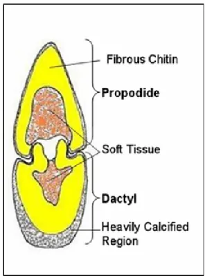
Apart from that, the Polypterus Senegalus, which belongs to the ancient family Polypteridae, still living today in the bottom of freshwater in Africa [26], is famous for its extra strong fish scale (Figure 1).
v. These selected role models shared a common cha– racteristic of hierarchical/multilayered structures. The Polypterus Senegalus fish scale and mantis shrimp limbs [27, 28] (Figure 2) show different material properties from the outer layer to the inner layer: in particular, the thickness of outer layer is higher than the inner one and the modulus of outer layer is higher than the inner layer one, therefore protecting the latter from damage.
In this Principles Extraction phase, the core principles were extracted according to the need of the design. Based on solutions among the role models, several principles were extracted as follows:
a. The thicknesses of each layer of material increase from the outer layer to the inner layer.
b. Modulus of materials decreases from the outer layer to the inner layer.
c. The density of the outer layer material is higher than the inner materials.
vi. Principle Application Phase: as the important principles were identified and extracted, the biomimetics approach was continued by translating principles from biological into engineering aspects. This included introduction of new constraints and criteria which encompassed the selected materials, manufac– turing process or technologies availability.
There are three main principles shared by biological models which include thickness, density and Young's modulus of different layers. The Figure 3 shows the
110 ▪ VOL. 46, No 1, 2018 FME Transactions conceptual design of the laminate composite that was
mimicked from the biology solution. This composite was considered as hybrid composite as a layer of composite laminate was bonded with a relatively soft material.
Figure 1. Optical micrograph of the cross section of P.
Senegalus fish scale.
Figure 2. Cross section of the shell of shrimp hammers.
Figure 3. Conceptual design of composite laminate.
2.2 Target material preparation
The ballistic events occurring on the targets are consi– dered as high velocity impacts: the target’s ballistic
performance highly depends on its material properties around the impact zone [29-31].
Therefore the target used for the numerical simulation analysis was a square plate with side dimension equal to 70 mm and different thicknesses.
The material selected for the strike face of the shield is T700 carbon fibre reinforced with 3234 epoxy for the high modulus and high tensile strength properties of carbon fibres. The materials were compressed at a pressure of 0.5 MPa and cured for 90 minutes at 130 °C as mentioned in [32], from which reference properties exposed in Table 1 are taken. Each layer of the unidirectional composites may be referred as a ‘ply’ or ‘lamina’, as shown in Figure 4. The fibre volume fraction, Vf, of the composites is 60.2 ± 1.5%. The material properties of each unidirectional lamina are listed in Table 1 (all the tables are reported at the end of the paper, for their better visibility). Various fibre orientations such as [0/90], [0/±45], [±30/90] and [0/±30/±60/90] with two difference thicknesses of 1.5 mm and 3 mm were selected in the analysis. Table 2 shows the details of each CFRP target.
Table 1. T700/epoxy laminate properties
Property Value Fibre volume fraction (%) 60.2±1.5
Denisty (kg/m3) 1570
Orthotropic Elasticity Young Modulus X (GPa) 132 Young Modulus Y (GPa) 10.3 Young Modulus Z (GPa) 10.3 Poisson's Ratio XY (GPa) 0.25 Poisson's Ratio YZ (GPa) 0.38 Poisson's Ratio XZ (GPa) 0.25 Shear Modulus XY (GPa) 6.5 Shear Modulus YZ (GPa) 3.91 Shear Modulus XZ (GPa) 6.5
Orthotropic Stress Limits Tensile Stress X (MPa) 2100 Tensile Stress Y (MPa) 24 Tensile Stress Z (MPa) 65 Compression Stress X (MPa) 1050 Compression Stress Y (MPa) 132 Compression Stress Z (MPa) 132
Shear Stress X (MPa) 75
Shear Stress Y (MPa) 75
Shear Stress Z (MPa) 75
Table 2. Details of CFRP targets
No. Fiber orientation No. of Ply Thickness (mm) 1 [0/90]9 18 1.5 2 [0/±45]3s 18 1.5 3 [±30/90]3s 18 1.5 4 [0/±30/±60/90]3 18 1.5 5 [0/90]9s 36 3.0 6 [0/±45]6s 36 3.0 7 [±30/90]6s 36 3.0 8 [0/±30/±60/90]6 36 3.0
In the case of polycarbonate, a previous study had identified five main types of behaviour under ballistic impact: these are elastic dishing, pedalling, deep penetration, cone cracking and plugging. As a result,
FME Transactions VOL. 46, No 1, 2018 ▪ 111 different thickness of the PC would have different
response to the impact [33]. As investigated, thin PC sheet do perform better in term of kinetic energy absorption compared to thick PC sheet. For this reason, PC has been selected as the inner layer materials for the development of the bullet proof shield.
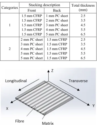
Based on both CFRP and PC characteristic, both materials were combined to create a hybrid composite, in which a layer of composite was bonded with a layer of relatively soft thermoplastic material. PC is selected as the inner layer materials for the development of the bullet proof shield for its behaviour. Target specimens made from hybrid composite materials are described in Table 3.
Table 3. Descriptiion of hybrid material target
Stacking description Categories Front Back Total thickness (mm) 1 1.5 mm CFRP 1.5 mm CFRP 1.5 mm CFRP 1.5 mm CFRP 1.5 mm CFRP 1 mm PC sheet 2 mm PC sheet 3 mm PC sheet 4 mm PC sheet 5 mm PC sheet 2.5 3.5 4.5 5.5 6.5 2 2 mm PC sheet 3 mm PC sheet 4 mm PC sheet 5 mm PC sheet 5 mm PC sheet 1.5 mm CFRP 1.5 mm CFRP 1.5 mm CFRP 1.5 mm CFRP 1.5 mm CFRP 2.5 3.5 4.5 5.5 6.5
Figure 4. The coordinate system of a unidirectional composite lamina.
2.3 Numerical analysis
The ballistic behaviour of the targets was investigated by measuring the impact made by a spherical projectile on it. The experiment was done through simulation using Abaqus/Explicit software. Validation was then performed to obtain data by running another simulation model using ANSYS/Dynamic Explicit software (Figure 5) and compare the two with existing results from the previously mentioned similar research [31], which also used the same T700/epoxy laminate as CFRP.
Two methods of impact simulated for analysis were adopted, namely normal impact and oblique impact. For all the normal impact events, the targets were impacted at the mid-span at impact velocities ranging from 100 to 400 m/s. The ballistic performances of the targets were reviewed and the most suitable material configuration was selected. Following this, the selected
configuration was further analysed using oblique impact method with an impact velocity of 300 m/s. The diameter of the spherical projectile is 6 mm with a weight of 0.85 g.
Figure 5. Example of ballistic impact simulation model using ANSYS.
2.4 Design analysis
The design development of bullet proof composites shield analysis started with raw data collection and identification of customer needs. Review and survey ca– rried out from customers yielded out a list of product design specifications:
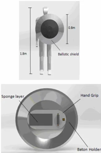
• The overall weight of the shield must be less than 4.5 kg.
• The size of the shield must fully cover human’s torso • The shield must come with a baton holder.
• The shield shall not block the view of the user. Three concepts were generated and evaluated. Each design concepts must consist of strike face, baton holder, hand grip and view window as shown in Figure 6, 7 and 8.
In concept 1 (Figure 6), the extra layer of hybrid material of strike face with cone shaped provides an oblique surface to the projectile during impact. A simple O-ring is used for hanging the baton. This method is simple and has almost no effect on the total weight of the bullet proof shield. The hand grip position is offset against the centre of the shield and a layer of sponge is introduced as a shock absorber. There is no view window in this design concept due to its medium size, as the shield does not block the view of the user.
The proposed concept 2 (Figure 7), inspired by stealth aircraft is the combination of multiple flat surfaces to reduce orthogonal impact and able to resist higher impact velocity of projectiles with the same thickness of the shield. The design of size and shape was meant to effectively protect area of head and body. Fabric belts with arm rests provide comfort to the user and a bar is attached at the back of the shield, so that the user can grip it easily. An elastic clipper is attached next to the handle where a baton can be easily taken out in response to a situation. At the top part, a small view window is riveted to the shield.
The proposed concept 3 is an improved version of the existing riot shield. The shape of the shield remains
112 ▪ VOL. 46, No 1, 2018 FME Transactions rectangular and the strike face is concave in shape. The
hand grip consists of two simple U-shaped bars wrapped in a thick layer of sponge. A baton holder formed by thin metal sheets provide a place for the baton to support, but its position is changed from vertical to horizontal, so that the baton can be taken out easily in response to a situation. The view window is framed inside the composite.
Figure 6. Front and back view for proposed concept 1.
Each proposed concept was evaluated by seven criteria using scoring matrix technique, as shown in Table 4.
The concept that scored best in the matrix, was selected to proceed with design finalizing. Further improvements were carried out on the proposed concept 3 to address its limits. The final concept of the shield significantly consist of two parts (Figure 9), the upper one being a transparent PC strike face, also functioning as a view window, whereas the lower one is the strike face with a combination of CFRP laminate with PC material. Although the upper part of the shield is not covered with CFRP laminates, the thickness of the PC is larger than lower part as it is needed to achieve the ballistic limit velocity of 300 m/s.
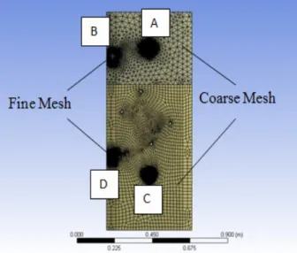
In order to ensure that the final product achieved the design specifications, the final product was numerically analysed again in a situation where four locations were impacted by 6 mm diameter steel ball bearing at impact velocities of 300 m/s and 305 m/s. For an effective meshing on the models, the sphere of influence method was applied, so that only the impact zone assigned had a fine mesh size, while other parts were coarse mesh size. The meshed model is shown in Figure 10.
Figure 7. Front and back view for proposed concept 2.
FME Transactions VOL. 46, No 1, 2018 ▪ 113
Table 4. Concept scoring matrix (Score 1=very bad; Score 5=very good)
No Criteria Weight Concept 1 Concept 2 Concept 3
1 Ease of Manufacture 20% 3 2 4 2 Ease of Maintenance* 15% 2.8 2.4 3.2 3 Aesthetic* 5% 2 3.4 3.8 4 Area of Protection* 20% 1.6 2.8 4.4 5 Ease of Handling* 10% 2.4 2.6 3.4 6 Portability* 25% 3 3 3.6 7 Storage* 5% 3 3 3.4 Total weight Score 2.58 2.65 3.76
Rank 3 2 1
Continue? No No Yes
Figure 9. Isometric view of the final concept.
Figure 10. The meshed model for simulation.
3. RESULTS AND DISCUSSION 3.1 Validation
Both results show a good agreement with each other, as can be seen in Figure 11, but it needs also to be reported that the numerical settings of ANSYS/Explicit Dynamic
in this result can only be considered acceptable with some degree of accuracy. Thus, further experimental work shall be conducted in the future to further validate the results from the numerical simu–lation analysis.
Figure 11. Graph of impact velocity versus residual velocity of CFRP targets with 1.5 mm thickness.
3.2 Ballistic impact velocity
The determination of the ballistic impact velocity requires that a limit is determined at which the projectile passes from impacting the target and penetrating it, therefore keeping a residual velocity, to having velocity reduced to zero at some point. It can be noticed, as from Figure 12, that the projectile hit the 5.5 mm PC target being rebounded at the impact velocity of 327 m/s with residual velocity reduced at almost zero at 105 µs, then increased again.
The latter phenomenon is happening due to the ela– stic recovery of the targets where the PC materials acted like a spring to store the energy from the projectile initially and then transferring it back to the projectile. The minimum residual velocity of the projectile was not achieved exactly at zero velocity due to the automatic time step control of the simulation programme. The problem could be solved by reducing the dimension of steps.
Since only the residual velocity of the projectile is concerned, the control of time steps remains in default setting. On the other hand, the example of the projectile perforating the target could be observed at impact velocity of 328 m/s. Furthermore, the velocity of the projectile started with 328 m/s is reduced, yet it always maintains a certain rather constant and absolutely not negligible velocity. This indicates that the projectile perforated the target and travelled with a velocity. Thus, we can conclude that the 5.5 mm thickness of PC has a
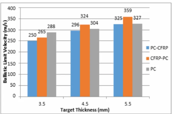
114 ▪ VOL. 46, No 1, 2018 FME Transactions ballistic limit velocity of 327 m/s while the ballistic
limit velocities of other targets are shown in Figure 13. As a whole, the increase of the target thickness leads to the increase of the ballistic limit velocity. The PC target also shows a superior ballistic performance as opposed to PC-CFRP and CFRP-PC when the thickness is thin, but this is not applicable for a higher level of thickness. This phenomenon takes place due to different impact responses between thin and thick PC plates [34]. Dishing is well known to take place in thin PC plates, and it is also increased by applying resin coatings so to provide different optical characteristics, which are more of interest in the application of these materials for recording devices, such as CDs [35].
Considering the projectile impacting the thin PC plate, stretching deformation (dishing) and yielding on the circular region of the plate surrounding the sphere projectile were shown. As for the thin PC, dishing is a dominant kinetic energy absorption mechanism, in which case a large amount of energy can dissipate. As the thickness of the plate increases, the degree of dishing is gradually reduced. Hence, the total amount of dissipated kinetic energy reduces. As a result, a small zone of yielding and bulging occurs on the back face of the target. The conclusion is that a higher degree of dishing can dissipate more kinetic energy therefore increasing the ballistic limit velocity of the material.
Figure 12. Graph of impact velocity versus time of targets with 5.5 mm thickness.
Figure 13. Ballistic limit velocity of various targets.
When comparing the stacking sequences, CFRP-PC always has higher ballistic limit velocity than PC-CFRP. Different stacking sequences result in different deformation on the target. The high modulus CFRP indicates hard and brittle characteristics, while and PC
depicts a ductile character. In terms of energy absorption mechanism, CFRP tends to absorb kinetic energy from the projectile by fibre breakage or matrix cracking. For instance, the PC material, elastic and plastic deformations are the main energy absorption mechanisms. By placing CFRP as the outer surface and PC as the inner surface, these materials do not influence each other during the energy absorption. However, with the reversed stacking sequence, the high modulus material of CFRP has restricted the degree of dishing of the PC thereby reduced the total energy absorption.
In design analysis, impact on four different locations on the shield been simulated. The residual velocity of the projectile versus time was plotted in Figure 14. More specifically, materials on locations A and B are 4.5 mm thick PC sheets, whereas in contrast materials on location C and D were the hybrids of 1.5 mm CFRP - 3 mm PC.
The trends of projectile residual velocity are the same for all locations and impact velocities: in contrast, the deformations were quite different. In particular, the residual velocity of the projectile on location A and C started to decrease at time 0 second, but the velocity of projectile on location B and D are not due to the different initial distance between projectile and shield. Projectile on location A and C is placed nearer to the shield compare with B and D. It happens because the different material configuration of shield. PC tends to deform in plastic manner where the thin PC tend to deform elastically. As a consequence, thin PC needs a longer time to absorb all kinetic energy from the projectile to stop when compared with thick PC.
Figure 14. Graph of residual velocity versus time at different locations over the sample.
4. CONCLUSION
Two biological models were selected in view of an improvement of the ballistic impact resistance of materials. The inspirations from fish scale and mantis shrimps have successfully been transferred into the engineering application by using the biomimetic approach. The numerical analyses of the impact resi– stance of materials suggest that the one with the conf– iguration inspired from nature offers a better ballistic impact performance. However, more experimental or empirical studies are required to further investigate the results generated in this work.
FME Transactions VOL. 46, No 1, 2018 ▪ 115 As for the shield design, some limits of the selected
concept were addressed. The resulting final concept of the bullet proof shield is rectangular curved with dimensions around 1175 x 500 mm. The estimated overall weight of the shield is 4.27 kg and its thickness is 4.5 mm. In short, the final concept of bullet proof shield is designed and it achieved the desired specifications.
ACKNOWLEDGMENTS
This work is financed under project of Mechanical Per– formance of Polyurethane Foam Fill with Kenaf/GFRP Recyclate (RUG). No. Vot: Q.J130000.2622.13J89. REFERENCES
[1] Bar-Cohen, Y.: Biomimetics: mimicking and inspired-by biology. Jet Propulsion Lab, California Institute of Technology, Pasadena, 2005.
[2] Helms, M., Vattam, S. and Goel, A.: Biologically Inspired Design: Process and Products, Design Studies, Vol. 30, No. 5, pp. 606-622, 2009.
[3] Pavlovic, A., Fragassa, C. and Disic, A.: Comparative numerical studies of projectile impacts on reinforced concrete validated by experimental measures, Composites Part B, Vol. 108, pp. 122-130, 2017.
[4] Tanasković, J.D., Milković, D.D., Lučanin, V.J. and Simić, G.Z.: Experimental and numerical determination of tube collision energy absorbers characteristics, FME Transactions, Vol. 40, No.1, pp. 11-16, 2012.
[5] Callister, W.D.: Materials Science and Engineering. An Introduction, John Wiley & Sons, Hoboken, 2003.
[6] De Paola, S., Minak, G., Fragassa, C., Pavlovic, A.: Green Composites: A Review of State of Art. In: Proceeding of 30th Danubia Adria Symposium on
Advanced Mechanics, Primosten, Croatia, 25-28 September, 2013, pp. 77-78, ISBN: 978-953-7539-17-7.
[7] Hyseni, A., De Paola, S., Minak, G. and Fragassa, C.: Mechanical Characterization of EcoComposites. In: Proceeding of 30th Danubia Adria Symposium
on Advanced Mechanics, Primosten, Croatia, 25-28 September, 2013, pp. 175-176, ISBN: 978-953-7539-17-7.
[8] Fragassa C: Effect of Natural Fibers and Bio-Resins on Mechanical Properties in Hybrid and Non-Hybrid Composites, in: Proceedings of the 8th Conference on Times of Polymers & Composites: From Aerospace to Nanotechnology. Vol. 1736, No. 4949693, 2016 doi: 10.1063/1.4949693.
[9] Kreculj, D., Rašuo, B., Review of impact damages modelling in laminated composite aircraft structures, Technical Gazette, Vol.20 No.3, June 2013, pp. 485-495.
[10] Rasuo, B.: An Experimental Methodology for Evaluating Survivability of an Aeronautical Constructions from Composite Materials: An Overview, International Journal of Crashwort–
hiness, Volume 12, Issue 1, Taylor & Francis, London, 2007, pp. 9-15.
[11] Zhang, D., Sun, Y., Chen, L. and Pan, N.: A comparative study on low-velocity impact response of fabric composite laminates, Materials and Design, Vol. 50, pp. 750-756. 2013.
[12] Saghafi, H., Brugo, T., Zucchelli, A., Fragassa, C. and Minak, G.: Comparison the effect of pre-stress and curvature of composite laminate under impact loading, FME Transactions, Vol. 44, No. 4, pp. 353-357, 2016.
[13] Naik, N.K. and Doshi, A.V.: Ballistic impact behaviour of thick composites: Parametric studies, Composite Structures, Vol. 82, No. 3, pp. 447-464. 2008.
[14] Carrillo, J.G, Gamboa, R.A., Flores-Johnson, E.A. and Gonzalez-Chi, P.I.: Ballistic performance of thermoplastic composite laminates made from aramid woven fabric and polypropylene matrix, Polymer Testing, Vol. 31, No. 4, pp. 512-519, 2012.
[15] Hosur, M.V., Vaidya, U.K., Ulven, C. and Jeelani, S.: Performance of stitched/unstitched woven carbon/epoxy composites under high velocity impact loading, Composite Structures, Vol. 64, No.3-4, pp. 455-466, 2004.
[16] Fragassa, C., Pavlovic, A. and Santulli, C.: Mechanical and impact characterisation of flax and basalt fibre bio-vinylester composites and their hybrids, Composites - Part B, 2017, doi: 10.1016/j.compositesb.2017.01.004.
[17] Boria, S., Pavlovic, A., Fragassa, C. and Santulli, C.: Modeling of Falling Weight Impact Behavior of Hybrid Basalt/Flax Vinylester Composites, Pro– cedia Engineering, Vol. 167, pp. 223–230, 2016.. [18] de Camargo, F.V. and Pavlovic, A.: Fracture
Evaluation of the Falling Weight Impact Behaviour of a Basalt/Vinylester Composite Plate through a Multiphase Finite Element Model, Key Engineering Materials, Vol. 754, pp. 59-62, 2017.
[19] Zivkovic, I., Pavlovic, A., Fragassa, C. and Brugo, T.: Influence of moisture absorption on the impact properties of flax, basalt and hybrid flax/ basalt fiber reinforced green composites. Composites Part B, Vol. 111, pp. 148-164, 2017.
[20] Zivkovic, I., Pavlovic, A. and Fragassa, C.: Improvements in wood thermoplastic composite materials properties by physical and chemical treatments. International Journal of Quality Research; Vol. 10, No. 1, pp. 205-218, 2016.
[21] Benyus, J., Biomimicry: Innovation Inspired by Nature, Harper Perennial, New York, 2002.
[22] Helms, M., Vattam, S.S. and Goel, A.K.: Biologically inspired design: process and products, Design Studies, Vol. 30, No. 5, pp. 606-622, 2009. [23] Lindemann, U. and Gramann, J.: Engineering
Design Using Biological Principles, in: Procee– dings of International Design Conference, 18-21.05.2004, Dubrovnik.
116 ▪ VOL. 46, No 1, 2018 FME Transactions [24] Espinosa, H.D. et al.: Merger of structure and
material in nacre and bone – Perspectives on de novo biomimetic materials, Progress in Materials Science, Vol. 54, No. 8, pp. 1059-1100, 2009. [25] Meyers, M.A., Chen P-.-Y., Yu-Min Lin, A. and
Seki, Y.: Biological materials: structure and mechanical properties, Progress in Materials Science Vol. 53, pp. 1-206, 2008.
[26] Bruet, B.J.F., Song, J., Boyce, M.C. and Ortiz, C.: Materials design principles of ancient fish armour, Nature Materials, Vol. 7, No. 9, pp. 748-56, 2008. [27] Barthelat, F.: Biomimetics for next generation
materials, Philosophical Transactions of The Royal Society A, Vol. 365, No. 1861, pp. 2907-2919, 2007. [28] Barthelat, F.: Nacre from mollusk shells: a model for high-performance structural materials, Bioins– piration&Biomimetics, Vol.5,No. 3, pp. 1-9, 2010. [29] Hazall, P.J., Kister, G., Stennett, C., Bourque, P. and Cooper, G.: Normal and oblique penetration of woven CFRP laminates by a high velocity steel sphere, Composites Part A, Vol. 39 No. 5, pp. 866-874, 2008.
[30] Lopez-Puente, J., Zaera, R. and Navarro, C.: Experimental and numerical analysis of normal and oblique ballistic impacts on thin carbon/epoxy woven laminates, Composites Part A, Vol. 39, No. 2, pp. 374-387, 2008.
[31] Cantwell, W.J. and Morton, J.: Impact perforation of carbon fibre reinforced plastic, Composites Science and Technology, Vol. 38, No. 2, pp. 119-141, 1990.
[32] Wang, B., Xiong, J., Wang, X., Ma, L., Zhang, G.Q., Zhi. Wu, L.Z. and Feng, J.C.: Energy absorption efficiency of carbon fiber reinforced polymer laminates under high velocity impact, Materials and Design, Vol. 50, pp. 140-148, 2013. [33] Wright, S.C., Fleck, N.A. and Stronge, W.J.:
Ballistic impact of polycarbonate- an experimental investigation, International Journal of Impact Engineering, Vol. 13, No. 1, pp. 1-20, 1993.
[34] Takeda, Y., Umezawa, T. and Chiba, K.: Topographical evaluation of optical disks with polycarbonate substrates in the manufacturing process, Applied Optics, Vol. 38, No. 35, pp. 7282-7287, 1999.
[35] Beaumont P.W.R., Soutis C. and Hodzic A. (Editors): Structural integrity and durability of advanced composites: Innovative modelling methods and intelligent design, Woodhead Publishing - Elsevier, Cambridge, UK, 2015.
ПОТЕНЦИЈАЛ ДИЗАЈНА БИОМИМЕТИКЕ У РАЗВОЈУ МАТЕРИЈАЛА ОТПОРНОГ НА УДАРЦЕ СА Хасан, К. Сантули, М. Ј. Б. Јахја, Ц. Л. Ганг, М. Н. Ф. Б. Абу Бакар Отпорност на балистичке ударце је основни квалитет за материјале који се користе у заштитним штитовима. У овом случају, биомиметички дизајн приступ коришћен је за побољшање постојећег дизајна штита проналажењем решења у природи. Принципи су изведени из биолошких модела, као што су рибља крљушт, шкампи, како би се побољшала ударна отпорност штита. Ови модели указују на то да вишеслојна структура материјала показује супериорне карактеристике отпорности на ударце у случају да је крутост спољашњих слојева знатно већа од унутрашњих слојева, а дебљина слоја повећава се од спољашњих према унутрашњим слојевима. Да би потврдили овај исказ, материјали са епоксидом ојачаним угљеничним влакнима (ЦФРП) као спољашњи слојеви и поликарбонат (ПЦ) као унутрашњи су дизајнирани и нумерички анализирани. Такође су анализирани чисти поликарбонатни узорци ради упоређивања. Резултати су показали да биомиметички конструисани композити имају већу балистичку граничну брзину од контролних узорака за исту дебљину.