A. Bertei I - INTRODUCTION
I – INTRODUCTION
I.1 – Introduction to fuel cells; I.2 – Anionic and protonic solid oxide fuel cells; I.3 – The IDEAL-Cell concept; I.4 – Aims of modelling; I.5 – References.
I.1 – Introduction to fuel cells
Fuel cells are electrochemical devices that convert the chemical energy of the reactant species (i.e. combustible and combustive agent) directly into electric energy without passing through a thermodynamic cycle in which the chemical energy is converted first into heat and then into mechanical or electric energy (fig. I.1). If we compare fuel cells with other devices such as gas or steam turbines1 we will find better efficiencies (defined as the ratio of the electric energy produced and the chemical energy supplied) because the conversion way is direct, so there is not any thermodynamic drawback (i.e. the passage through the production of an “incoherent” form of energy such as heat). This is possible because in fuel cells reagents do not meet directly but they are physically separated, the connection is made by an electric circuit; on the other hand, in turbines and in similar ways of conversion, combustible and combustive agent are intimately mixed together. Normally, air is the combustive agent and hydrogen is the combustible but we can also use respectively pure oxygen or methane (it is possible to use methane only for solid oxide fuel cells).
fig. I.1 – Comparison between thermodynamic and electrochemical conversion of chemical energy.
1 It is possible to make this comparison because the starting source of energy (i.e. chemical energy of
combustible and combustive agent) and the final product (i.e. electric energy) are the same, only the way to pass from one to other changes.
A. Bertei I - INTRODUCTION
Starting from 1980s, the importance of fuel cells is increased because they produce the most useful kind of energy (electricity) with high performances coupled with an optimal impact on environment (there is not any direct combustion, so pollutants are not produced). Sometimes also heat at high temperature is produced and it can be used in other applications as in combined cycles (remember that, according to the second law of thermodynamics, the fraction of heat that can be converted into mechanical or electric energy is higher as its temperature is higher).
Strictly on an energetic-economic point of view, an electrochemical device is competitive with other systems of energy conversion if we are able to maximize its efficiency while maintaining low costs of production and maintenance. Thus, the aim of the design should be the minimization of the energetic losses (e.g. resistances, dispersions, etc.) and of the cost of materials and realization of the facility.
The same process of electrochemical conversion of energy can be found in piles with the same advantages described before. The technological difference between piles and fuel cells concerns the availability of the output (i.e. electric power): piles are discontinuous suppliers of electricity, they produce a certain quantity of electric energy proportional to the amount of reagents inside them; fuel cells are continuous suppliers of electric power because combustible and combustive agent are supplied to the device with continuity. Clearly, piles can be sometimes recharged, but this does not change the discontinuity of the production of energy.
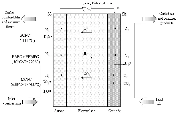
Concerning the principles of functioning, fuel cells are made of two electrodes, anode and cathode, where semi-reactions respectively of oxidation and reduction happen, and an electrolyte. The classification of fuel cells reflects the nature of the electrolyte, as chemical species that participate at the reaction, temperature and the resistance at certain pollutants of the system depend principally on the electrolyte. There are 5 classes of fuel cells (see also fig. I.2):
• PEFC (Polymer Electrolyte Fuel Cell): here a polymeric electrolyte (i.e. a membrane that permits the exchange of ions) with a high protonic conductivity is used. They work at low temperatures (70-100°C) and use carbon as electrolyte over which platinum (i.e. the catalyst) is dispersed. They can supply high current density, close to 2A/cm2, and can be organized into compact and light structures with high specific power; poisoning by carbon monoxide (10ppm) may affect the performance of the cell;
A. Bertei I - INTRODUCTION
fig. I.2 – Schematic representation of different types of fuel cells (Campanari, 2001).
• AFC (Alkaline Fuel Cell): the electrolyte is KOH that allows the conduction of OH-; operating temperatures are between 120°C and 250°C. Electrodes are made of nickel or carbon covered with electrocatalysts as silver or metal oxides. Potassium hydroxide is poisoned by CO2, so H2 and O2 with very high purity are
needed;
• PAFC (Phosphoric Acid Fuel Cell): here acid phosphoric is used, sometimes hold in a matrix of SiC, to allow the passage of protons from anode to cathode in the range 150-220°C. Electrodes have a carbon base covered with platinum; anode suffers the presence of CO or sulfur compounds. This technology was born in 1960s, it can be considered mature;
• MCFC (Melt Carbonate Fuel Cell): melt alkaline carbonates of sodium and potassium are kept in a matrix of LiAlO2; at 600-700°C the electrolyte becomes
conductive to the passage of CO3−2. Electrodes are made of nickel. The sulfur
content of gaseous streams must be kept below 0.5ppm;
• SOFC (Solid Oxide Fuel Cell): they use a solid electrolyte that allows the ionic conduction of current at high temperature. Normally, an anionic conducting electrolyte, such as Yttria Stabilized Zirconia, conduces oxygen ions (i.e. O-2) from cathode to anode at 700-1000°C, but also protonic conducting materials, such as Y-doped barium zirconate, can be used to conduce, in this configuration,
A. Bertei I - INTRODUCTION
protons (i.e. H+) from anode to cathode at lower temperatures than before. They do not need a careful depuration of reagents and they resist well to poisoning. Only SOFCs can use methane or carbon monoxide at the anode as combustible2, in all other cases hydrogen must be used as combustible; it means that a process for hydrogen production and purification (e.g. reforming of hydrocarbons, biomass, production of hydrogen through renewable energies, etc.) is needed. The current is produced in direct form (DC), so an inverter is needed if we want to convert it into alternating current to introduce to the electric net.
There are several advantages related to the use of fuel cells that justify the efforts of an intensive investigation:
• fuel cells have a good behaviour with respect to load variations, their performance does not change significantly if the nominal load decreases from 100% to 30%;
• there is not a direct combustion, so global efficiency is high and exhaust gases are NOx-free;
• absence of noise and vibrations (there are not parts in movement);
• big devices can be made by the union of smaller stacks;
• low operating costs (but very often fixed costs are high).
I.2 – Anionic and protonic solid oxide fuel cells
Solid oxide fuel cells (SOFCs) are the type of fuel cells in which research has the greatest interests to investigate because the expected performances and efficiencies are the highest coupled with the possibility to use methane or carbon monoxide instead of hydrogen at the anodic side (also a mixture of these gases can be used)3. Till now, improvements have been performed concerning materials, modelling and interconnections but there is not really a SOFC available for the market.
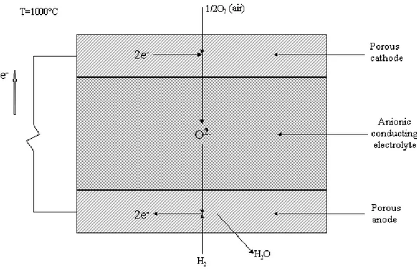
Historically, the anionic conducting SOFC (usually called with the general acronym SOFC) is the most studied kind of solid oxide fuel cell. The principle of operation is represented in fig. I.3 when hydrogen and oxygen are used as reactants; the principal
2 This is possible because the electrolyte brings oxygen ions instead of protons, so at the anodic side there
can be a combustible that does not produce H+ (compare with PACF or PEFC). In other words, in theory at the anode we could use any combustible able to react with O-2 generating products that can be carried away.
3 With the acronym SOFC we refer to Solid Oxide Fuel Cell, i.e. a fuel cell that uses a solid electrolyte
for the transport of ions (in solid phase) inside the cell. Generally speaking, the acronym SOFC is normally used to identify only anionic conducting solid oxide fuel cell, for protonic conducting solid oxide fuel cell the acronym PCFC is used. In the following we will always specify the nature of the cell.
A. Bertei I - INTRODUCTION
feature is the nature of the solid electrolyte that allows the passage of oxygen ions (O-2) and it does not conduct electrons. At the cathode the reduction of molecular oxygen occurs: oxygen into gas phase (i.e. the pores of the electrode) reacts with electrons that come from the external circuit, made of an electronic conductor, to produce oxygen ions O-2 on the anionic conducting phase. Oxygen ions migrate through the electrolyte towards the anode where molecular hydrogen reacts with them to produce water and electrons supplied on the external circuit.
fig. I.3 – Simplified scheme of an anionic conducting SOFC.
We resume the reactions that occur inside the cell using the subscripts “g” to indicate gas phase, “el” for the electronic conductor and “ACP” for the anion-conducting phase:
Cathode: 12O2(g) 2e(el) O(ACP2 )
−
− →
+ (reac. I.2.1)
Anode: H2(g)+O(−ACP2 ) →H2O(g)+2e(−el) (reac. I.2.2) Cell: H2(g) +12O2(g) →H2O(g) (reac. I.2.3)
The driving force of the process is the natural tendency of hydrogen and oxygen to produce water, the standard Gibbs free energy ∆G° of (reac. I.2.3) is less than zero4.
4 We are talking about a system at constant pressure and temperature, so the second law of
thermodynamics can be expressed in terms of Gibbs free energy. Remember that in this situation –∆G° represents the maximum work that the system can supply.
A. Bertei I - INTRODUCTION
Then, the global reaction occurs in this way because reactants are separated and the electrolyte does not conduct electrons, so electrons are forced to pass through an external electric circuit supplying directly electric energy to a user on the outside of the cell. Now, it should be clear that the total amount of energy that the reaction can supply, i.e. –∆G°, is totally available. During the processes there will be some losses of energy inside the cell, for example due to the resistances made by the electrolyte (i.e. ohmic resistance) or connected with the reactions at the electrodes (i.e. energy needed to provide an effective rate of reactions different from zero5).
The tendency of the global reaction shows up with a difference of electric potential between cathode and anode. At the cathode molecular oxygen tends to draw electrons from the external circuit to produce oxygen ions, it creates a lack of negative charge on the electron conductor at the cathodic side yielding a positive value of the potential Vcat.
At the anodic side, water and electrons are produced, so that on the electron conductor there is an excess of negative charge that yields a negative electric potential Van6. When
the external circuit is open, an equilibrium is reached and it yields a difference of potential Vcat – Van > 0 called open circuit voltage (OCV) that depends only on the
conditions of reagents and products (i.e. their temperatures and concentrations) according to the Nernst law: the OCV is bigger when concentrations of reagents (H2 and
O2) are big or the concentration of the product (H2O) is low and vice versa. When the
circuit is closed, a current (made of electrons) flows from cathode to anode through the external circuit due to this difference of potential (remember that the current flows from an high value of electric potential towards a lower one, so the convention is to consider current as the motion of positive charges; in this way, the flow of electrons is in the opposite direction).
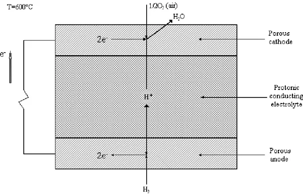
A protonic conducting solid oxide fuel cell (acronym: PCFC as Proton Conducting Fuel Cell) works in a similar way, the difference is the nature of the solid electrolyte that conducts protons (H+) instead of oxygen ions. In this configuration, at the anode molecular hydrogen leaves electrons on the electric conductor and produces protons that migrate towards the cathode where they combine with molecular oxygen and electrons
5 At the equilibrium, rates of direct and reverse reactions are equal. When there is a defined driving force,
i.e. when ∆G differs from zero, the global reaction (i.e. the algebraic sum of direct an reverse reactions) goes towards the direction to restore the equilibrium; in a real system this phenomenon happens with a global rate different from zero (we will call this limit case as reversible), so irreversibility produces losses of energy. In other words, we could say that in the irreversible situation a fraction of the available energy is spent to hold the reaction with a finite rate, so frictions, resistances, etc. are voices of lost energy.
6
This is a simplified (but easy to understand) way to explain the genesis of the difference of electric potential between cathode and anode.
A. Bertei I - INTRODUCTION
to create water (fig. I.4). Operating temperature could be lower than in the other case according to materials able to conduct protons in solid phase at 500-700°C (Kreuer, 2003; Thorel et al., 2009). Thus, the reactions are (the subscripts are the same as before, “PCP” means proton-conducting phase):
fig. I.4 – Simplified scheme of a protonic conducting SOFC.
Cathode: 12O2(g) +2H(PCP) +2e(el) →H2O(g)
− +
(reac. I.2.4) Anode: H2(g) →2H(+PCP) +2e(−el) (reac. I.2.5) Cell: H2(g) +12O2(g) →H2O(g) (reac. I.2.6)
All the considerations concerning the driving force and the genesis of OCV are similar as explained before. This kind of cell is still under development, the anionic one is more mature but not on the market yet (Thorel et al., 2009).
Generally speaking, both cells are thought for stationary applications at high temperatures compared with other types of fuel cells, so they can be used for continuous production of current in small or medium scale with high efficiency. It is difficult to imagine them placed in cars or trains due to their brittleness (electrolytes and other materials are usually ceramics) and to the long time needed to reach the normal regime.
A. Bertei I - INTRODUCTION
I.3 – The IDEAL-Cell concept
As presented above, two kinds of solid oxide fuel cells are in development; essentially, they differ on the nature of the solid electrolyte that affects the place where water is produced (anode for anionic type, cathode for protonic type). We talked about the advantages related to their use (e.g. high efficiency, possibility to use methane as combustible, etc.) but they have got also some drawbacks. Let us list here some features of the configurations (Thorel et al., 2009).
For the anionic type of cell (SOFC) we may say:
1. presence of water at the anodic side creates a corrosive atmosphere;
2. at the anode water dilutes the fuel, it leads to a lower value of OCV according to Nernst law and to difficulties to separate water from not reacted gases;
3. in the anode there is the counter-flow of fuel and water and this does not allow to reactant to reach freely the reaction site and to water to evacuate reducing the global efficiency;
4. the counter-flow of gases acts against the preliminary heating of the system; 5. the heat produced by the reaction is carried away by the mixture of not reacted
fuel and water;
6. anode can not be fully optimized for its basic purpose because it has the double function of providing the oxidation of hydrogen and of evacuating water.
We can repeat more or less the same drawbacks for the protonic type (PCFC):
1.presence of water at the cathodic side creates a corrosive atmosphere; up to now, there is not an available cathodic material;
2.water production at the cathode dilutes air, so the lower value of partial pressure of oxygen reduces the available OCV;
3.in the cathode there is the counter-flow of air and water and this reduces the global efficiency and acts against the preliminary heating of the device;
4.air and water carry away the heat produced by the reaction;
5.cathode can not be fully optimized for its basic purpose because it has the double function of providing the reduction of oxygen and of evacuating water.
As it can be seen, most of the drawbacks are due to the presence of water at one of the electrodes that does not allow a full optimization of the cell.
The IDEAL-Cell concept (Thorel et al., 2009) comes up to avoid these problems. The idea is to combine the anode and the electrolyte of a protonic SOFC with the cathode and the electrolyte of an anionic SOFC; these two parts are connected together by a
A. Bertei I - INTRODUCTION
porous composite layer of proton-conducting and anion-conducting materials called central membrane (CM). In this way, the cell is made of at least 5 layers: 3 porous composite (anode, cathode and central membrane) and 2 dense (protonic and anionic electrolytes). Fig. I.5 shows schematically the concept.
a)
b)
c)
fig. I.5 – The IDEAL-Cell concept: a) PCFC and SOFC; b) the combination; c) IDEAL-Cell.
A. Bertei I - INTRODUCTION
Let us remember all the reactions that occur inside the cell:
Cathode: 12O2(g) 2e(el) O(ACP2 )
−
− →
+ (reac. I.3.1)
Anode: H2(g) →2H(+PCP) +2e(−el) (reac. I.3.2) Central membrane: 2H(+PCP) +O(−ACP2 ) →H2O(g) (reac. I.3.3) Cell: H2(g) +12O2(g) →H2O(g) (reac. I.3.4)
The acronym IDEAL-Cell means “Innovative Dual mEmbrAne fueL Cell”; the adjective “Dual” refers to the fact that the cell is the combining of two types of cells. The acronym IDEAL shall not lead to misunderstandings: the IDEAL-Cell is a real operating fuel cell and the proof of the concept has been demonstrated experimentally in the last two years. Thus, it is not a schematic idealization, actually the IDEAL-Cell exists even if improvements must be done to reach significant performances.
The principal feature of the concept is referred to the water production: water is not generated at one of the electrodes but the recombination reaction happens in a third compartment. Thus, the main role is entrusted to the central membrane, a layer specifically dedicated at the water recombination; but it is also important that electrolytes must be dense to avoid the mixing of species.
The advantages that IDEAL-Cell offers compared to conventional anionic or protonic solid oxide fuel cells are:
1. the reduction of the corrosion at electrodes;
2. there is not any dilution of the fuel or air, so OCV is expected to increase and reagents can be reused again without the removal of water;
3. there is not any counter-flow of gases;
4. electrode polarizations (i.e. the losses of energy related to the reactions) are expected to decrease because the reactions are simpler and the absence of counter-flows may reduce concentration overpotentials (i.e. the amount of energy lost due to the arrival of reagents to the reacting site and the evacuation of products from it);
5. pure water and heat can be recovered from the central membrane;
6. the three compartments are independent, then pressure can be applied to anode and cathode;
A. Bertei I - INTRODUCTION
7. each compartment has a single specific role to play and can be optimized for its purpose.
It is clear that there are also some drawbacks:
1. the cell is made of at least five layers instead of three, it could increase ohmic resistances and it makes the assemblage more difficult;
2. several materials are used for the realization of the cell, some of them could not be compatible, especially in the same range of temperature (e.g. a substance could affect chemically another one, thermal expansion coefficients could be different, etc.): this fact reduces the choice of materials (Presto et al., 2009);
3. if a cylindrical design is used, the pressure inside the CM could increase too much7 affecting the mechanical resistance and the electrochemical behaviour of the system.
Note that, in general, the disadvantages mentioned above are technological, so we may hope that research on materials, preparations and assembling will lead to reduce the impact of these drawbacks on the performances of the IDEAL-Cell. At this state of the art it is very difficult to predict real future outcomes because only the concept has been demonstrated experimentally, at the moment there is not yet an accurate know how on substances and technologies, so extrapolations could be misleading. But, considering that the production of water does not happen at electrodes with all the advantages listed above, it is expected that electrical efficiency could increase up to 75% (compared with 50% and 60% respectively of SOFC and PCFC) and the costs could be lower mainly due to the absence of corrosion at the electrodes (Thorel et al, 2009).
To get an insight into the expected performances of the IDEAL-Cell, let us show some details concerning the energy balance of the whole cell at steady-state conditions when the cell works as a supplier of electric energy. If we apply the Kirchhoff second law (i.e. the conservation of energy in an electric circuit), according with the notations shown in fig. I.6, we will obtain the value of the difference of potential E exposed to the external circuit (i.e. the available difference of potential):
an PCE CM ACE cat el el(0) V (e) V V V V V V E = − =
∆
+∆
+∆
+∆
+∆
(eq. I.3.1) 7Note that in a cylindrical design layers are fine along the axial dimension (usually in the order of 50-100µm) but they have got big diameters compared with their thickness to produce a significant current. Now, at the electrodes hydrogen and air flow along the axial coordinate, in the CM the evacuation of water shall happen along the radial coordinate into a porous structure: this could lead to high pressure losses (i.e. to high values of pressure in the center of the CM)
A. Bertei I - INTRODUCTION
In particular:
cathodic loss: cat
eq ACP eq cat , el ACP el cat V (0) V (a) V V V η ∆ = − = − − (eq. I.3.2)
anionic electrolyte loss: ∆VACE =VACP(a)−VACP(b)=−RACE⋅I (eq. I.3.3)
CM loss: CM eq PCP eq ACP PCP ACP CM V (b) V (c) V V V η ∆ = − = − − (eq. I.3.4)
protonic electrolyte loss:∆VPCE =VPCP(c)−VPCP(d)=−RPCE⋅I (eq. I.3.5) anodic loss: ∆Van =VPCP(d)−Vel(e)=VPCPeq −Veleq,an −ηan (eq. I.3.6)
fig. I.6 – Schematic representation of the IDEAL-Cell in steady-state (ACP: anion-conducting phase; el: electric conductor; PCP: proton-anion-conducting phase).
It shall be clear the position of the points in fig. I.6:
• 0: point on the electric conductor at the cathodic terminal;
• a: point on ACP at the interface between the cathode and the anionic electrolyte;
• b: point on ACP at the interface between the anionic electrolyte and the CM;
• c: point on PCP at the interface between the CM and the protonic electrolyte;
• d: point on PCP at the interface between the protonic electrolyte and the anode;
• e: point on the electric conductor at the anodic terminal.
With the symbols RACE and RPCE we refer to respectively the ohmic resistance of the
anionic electrolyte and the protonic electrolyte (a linear behaviour of ∆VjCE with I is
assumed). With the symbols ηcat, ηCM, ηan we refer to the overpotentials of cathode,
central membrane and anode, defined as:
(
V V)
(
Vel(0) VACP(a))
eq ACP eq el cat = − − − η (eq. I.3.7) 0 a b c d e I I el ACP ACP PCP PCP el RexA. Bertei I - INTRODUCTION
(
V V)
(
VACP(b) VPCP(c))
eq PCP eq ACP CM = − − − η (eq. I.3.8)(
VPCPeq Veleq)
(
VPCP(d) Vel(e))
an = − − − η (eq. I.3.9)These overpotentials are referred to all the losses of energy that occur inside electrodes or CM, i.e. activation overpotentials (losses of energy to have a finite rate of the relative reaction), concentration overpotentials (losses of energy due to the supplying of reagents and discharging of products at the reaction site), ohmic overpotentials (losses of energy referred to the transport of charges inside electrodes or CM). They are normally functions of the current I (ηj increases if I increases) and they are an indirect
measurement of the irreversibility of the processes that happen inside electrodes or CM (at the equilibrium, when processes are reversible, overpotentials are equal to zero). In this notation, overpotentials are positive for positive values of I (i.e. when the fuel cell is working in the way of producing water and energy).
By combining all the equations together into (eq. I.3.1), it yields:
an CM cat PCE ACE I R I R OCV E = − ⋅ − ⋅ −η −η −η (eq. I.3.10)
in which OCV is calculated according to the Nernst equation of electrochemical equilibrium:
( )
− ° = − = 1/2 O H w g eq an , el eq cat , el 2 2 p p p ln F 2 T R OCV V VOCV (eq. I.3.11)8
OCV° is the value of OCV calculated in standard conditions, i.e. at partial pressures of species equal to 1atm; it can be demonstrated that the relationship between OCV° and
∆G° is expressed as:
F 2
G
OCV°=−∆ ° (eq. I.3.12)
8 It shall be noted that the Nernst law of equilibrium should be expressed using activities of species
participating at the reaction instead of their partial pressures. In this contest, the use of partial pressures makes the development of the equations easier to understand.
A. Bertei I - INTRODUCTION
Watching (eq. I.3.11) it should be clear that the dilution of the fuel (i.e. H2) has bad
effects on the performance of the cell: if partial pressure of hydrogen decreases the OCV decreases as already mentioned above.
Concerning the efficiency of the system, (eq. I.3.10) shows that if overpotentials and resistances are high (we may call them internal irreversibilities) the expected difference of potential between the terminals of the cell E will be low compared with OCV; it means that the device has a potential energy that it can supply (OCV) but due to irreversibilities it gives only a fraction of it (E). It is important to reduce overpotentials and resistances in order to achieve the maximum value of E/OCV, equal to 1. The ideal limit consists in the case at which E is equal to OCV for each current I (i.e. internal irreversibilities are zero), so the current will be determined only by the value of the external user (i.e. by Rex)9. Thus, the situation that we should try to reach consists in
increasing as much as possible the value of OCV (i.e. the maximum ideal energy that the system can supply) and decreasing internal overpotentials and resistances (i.e. the losses of energy within the cell).
I.4 – Aims of modelling
In the previous paragraph we said that the principal purpose of the design is to optimize the system to reach high values of difference of potential at the terminals, this can be done by increasing the OCV and decreasing internal losses. To do this it is important to have a clear comprehension of the processes that characterize the system in order to settle the modifications to do to increase the performances. But a simple qualitative understanding of the phenomena is not enough to reach this goal, we need a quantitative tool. In this contest, a model for the mathematical description of the whole system and of the elementary processes that compose it is a comprehensive tool.
9
In general the working condition, i.e. the couple of values E and I, is determined by both conditions inside the cell (overpotentials and internal resistances) and outside it (resistance on the external circuit); E is also equal to RexI, so by combining this equation with (eq. I.3.10) it yields:
ex PCE ACE an CM cat an CM cat PCE ACE ex R R R OCV I I R I R OCV I R + + − − − = ⇒ − − − ⋅ − ⋅ − =
η
η
η
η
η
η
Note that E ≥ 0 in working conditions (E = 0 means short circuit, i.e. the condition in which all the energy supplied by the cell is spent in internal irreversibilities). The product E·I represents the power that the cell supplies to the external user.
A. Bertei I - INTRODUCTION
Up to now, several models have been presented to describe the behaviour of electrodes in solid oxide fuel cells (Costamagna et al., 1998; Nam and Jeon, 2006; Zhu and Kee, 2008; Shi et al., 2007, Hussain et al., 2007). The real innovation of the IDEAL-Cell is represented by the central membrane, so we need a specific model to describe this porous composite layer; the approach that we will follow can be also applied to the mathematical description of the anode and the cathode. This model is an improvement of a model of the central membrane already presented (Ou et al. 2009).
The model of the central membrane that we will present is based on charge and mass balances, coupled with a physical-mathematical description of the morphology; it is not an equivalent circuit that would have the advantage to be simple to understand and to manage but it would not represent the physical reality of the system. It would be only a schematic representation in which elementary electric components (e.g. resistances, capacitances, etc.) should be associated to physical phenomena. Our model derives from the understanding of the elementary processes occurring inside the central membrane (i.e. kinetics, transports, etc.) strictly bonded with the physical behaviour of materials and chemical species. Then, for each phenomenon, after the idealization of its behaviour, a mathematical description is proposed. For example, if there is a flux of a quantity we represent it as the consequence of the unbalance of an opportune driving force: we will call them submodels. All submodels converge into the model of the central membrane providing a mathematical description of the system based on the physical explanation of elementary phenomena concretized in conservation balances. A direct consequence of this kind of approach is that the model needs as inputs only operating conditions and starting measurable parameters (e.g. conductivities of phases, diffusivities, particle size, etc.) even if sometimes specific measurements are needed and must be performed (for example for the estimation of kinetic parameters). This is made possible because we apply a physical description using physical quantities (e.g. concentrations, pressure, potentials, etc.). The outcomes are performance indexes (e.g. polarization resistance of the CM) coupled with fields of quantities inside the membrane (e.g. pressure, concentrations, potentials of phases, etc.).
The aims of the model are to help the explanation of experimental results obtained up to now with the existing cells (i.e. interpretative tool), to direct to new specific experiments and measurements to improve the understanding of the phenomena (i.e. investigative tool) and to predict performances and to optimize the design of the cell in order to maximize the efficiency (i.e. predictive tool for the design).
A. Bertei I - INTRODUCTION
I.5 – References
Campanari S., “Le Celle a Combustibile ad Ossidi Solidi e i Cicli Ibridi”, Corso di Tecnologie Avanzate per la Cogenerazione Diffusa, Milano, April 26-27 2001.
Costamagna P., Costa P., Antonucci V., “Micro-modelling of solid oxide fuel cell
electrodes”, Electrochim. Acta, 43, pp. 375-394; 1998.
Hussain M.M., Li X., Dincer I., “Mathematical modeling of transport phenomena in
porous SOFC anodes”, Intern. J. of Thermal Science, 46, pp. 48-56; 2007.
Kreuer K.D., “Proton-conducting oxides”, Annu. Rev. Mater. Res., 33, pp. 333-359; 2003.
Nam J.H., Jeon D.H., “A comprehensive micro-scale model for transport and reaction
in intermediate temperature solid oxide fuel cells”, Electrochim. Acta, 51, pp. 3446-3460; 2006.
Ou T., Delloro F., Nicolella C., Bessler W.G., Thorel A.S., “Mathematical Modelling of
Mass and Charge Transport and Reaction in the Central Membrane of the IDEAL-Cell”, SOFC-XI ECS Transactions 25, pp. 1295-1304; 2009.
Presto S., Barbucci A., Viviani M., Ihlan Z., Ansar A., Soysal D., Thorel A.S., Abreu J., Chesnaud A., Politova T., Przybylski K., Prazuch J., Brylewski T., Zhao Z., Vladikova D.E., Stoynov Z., “IDEAL-Cell, Innovative Dual mEmbrAnE fueL-Cell: Fabrication
and Electrochemical Testing of First Prototypes”, SOFC-XI ECS Transactions, 25, pp. 773-782; 2009.
Shi Y., Cai N., Li C., “Numerical modeling of an anode-supported SOFC button cell
considering anodic surface diffusion”, J. of Power Sources, 164, pp. 639-648; 2007. Thorel A.S., Chesnaud A., Viviani M., Barbucci A., Presto S., Piccardo P., Ilhan Z.,
Vladikova D., Stoynov Z., “IDEAL-Cell, a High Temperature Innovative Dual
mEmbrAne fueL-Cell”, SOFC-XI ECS Transactions, 25, pp. 753-762; 2009.
Zhu H., Kee R.J., “Modelling Distributed Charge-Transfer Processes in SOFC