24
3
3
Mo
M
o
du
d
u
l
l
at
a
t
i
i
on
o
ns
s
f
fo
o
r
r
Bl
B
l
ue
u
et
t
o
o
ot
o
th
h
3.1 Digital Modulation
Typically the objective of a digital communication system is to transport digital data between two or more nodes. In radio communications this is usually achieved by adjusting a physical characteristic of a sinusoidal carrier, that is either the frequency, phase, amplitude or combination thereof. This is performed in real system with a modulator at the transmitting end to impose the physical change to the carrier and a demodulator at the receiving end to detect the resultant modulation on reception. A complication is added by the noise and the radio propagation characteristic. Noise is contained in every real system and will result in a non zero probability of an error occurring on the demodulator, although different systems have different sensitivities to errors. Radio channels have different characteristics according to the communication systems, also weather conditions play a role. However, mobile communication systems operating in the VHF and UHF bands are typically not line-of-sight and therefore consist of the sum of signals from different paths (fading due to multipath waves). Potentially, this will result in Inter-Symbols Interference (ISI), due to the delay, and amplitude variations with time and distance. Physical objects will also cause ‘shadowing’, resulting in loss of signal. Moreover, Doppler effect appears when communicating devices are moving with a large relative speed.
The Bluetooth communication system is designed for radio communication in short distance and low device speed, therefore in this analyses a schemed channel by an Additive White Gaussian Noise (AWGN) is used. As mentioned in the first chapter, the Radio part of Bluetooth uses three kinds of Digital Modulations to
Chapter 3 Modulations for Bluetooth
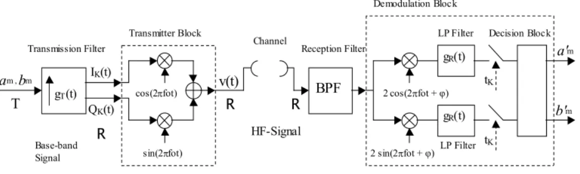
25 transmit data: GFSK, π/4-DQPSK and 8-DPSK. The two latest kinds of modulation follow a general scheme relative to the QAM (Quadrature Amplitude Modulation), in order to transmit a complex symbol and hence a number of data twice higher, as shown in the following figure:
a'm T gT(t) Transmission Filter IK(t) R Transmitter Block cos(2πfot) sin(2πfot) v(t) R Base-band Signal HF-Signal Channel BPF Reception Filter 2 cos(2πfot + φ) 2 sin(2πfot + φ) gR(t) gR(t) Demodulation Block tK tK LP Filter LP Filter am , bm b'm Decision Block R
QK(t)
Figure 3.1 – QAM Digital Modulation scheme.
In this model, the channel only adds a white Gaussian noise to the transmitted signal. This implies that the channel’s time response is unitary (flat amplitude frequency response and no phase distortions), thus with unlimited or infinite bandwidth. The digital data Source sends a slot of binary digits to the Modulator, which in this case, modifies in a digital way the phase of the sinusoidal carrier. A Base-band representation is useful in order to obtain a scheme, that can be analysed as shown in Figure 3.2:
s(t) C
AWGN
Channel Reception Filter
t0 + kT b'm Decision Block gT(t) gR(t) am , bm T
Transmission Filter Sampling
a'm
T
T
C C
š(t) u(t) u(kT)
Figure 3.2 – QAM Base-band representation.
In the continuous-time case, any bandpass signal s(t) with carrier frequency Fc can
Chapter 3 Modulations for Bluetooth 26
{
}
, where C. Re 2 ∈ = s(t)e s(t) s(t) c j πFct c (3.1)sc(t) is called the complex envelope of the modulated signal. Furthermore, two
other equivalent representations are:
, 2 sin 2 cos 2 cos[ πFt θ(t)] I(t) ( πFt) Q(t) ( πFt) (t) s s(t)= c c + = c − c (3.2)
where the complex signal sc(t) is defined in terms of the two real signals I(t) and
Q(t) by: , ) (t j c c(t) I(t) jQ(t) s(t)e s = + = θ (3.3) = + = ) ( ) ( arctan ) ( ) ( 2 2 t Q t I θ(t) t Q t I (t) sc
[ ]
[ ]
= = θ(t) (t) s t Q θ(t) (t) s t I c c sin ) ( cos ) (where I(t) is called In-phase component and Q(t) is called the Quadrature-phase component.
The characterisation of continuous-time signals given above can be easily carried over to discrete-time. Such signals are usually obtain by uniformly sampling a continuous-time signal at a sufficiently high rate, in order to produce a discrete-time signal, which can be easily elaborated within these electronic devices. The discrete-time signal is obtained from continuous-time one, through the sampling, with the following relation:
s(t) → s[k] , where bys[k]=s(t)t=kT , thus the following equations are obtained:
, ] [ ] [ ] [ ] [ j [k] c c k I k jQ k s k e s = + = θ (3.4) = + = ] [ ] [ arctan ] [ ] [ ] [ ] [ 2 2 k Q k I k θ k Q k I k sc
(
)
(
)
= = . ] [ sin ] [ ] [ ] [ cos ] [ ] [ k θ k s k Q k θ k s k I c cThe sampling rate Fs in Hz is enough to satisfy the Nyquist’s Criterion of
c IF
s F B
F ≥ 2 + , where FIF is the intermediate carrier frequency in Hz and Bc is the
Chapter 3 Modulations for Bluetooth
27 Finally, the equation [ ] Re [ ] 2
= F k F j c c IF e k s k
s π , referred to the bandpass signal
can be obtained, where the parameter FIF/Fc indicates the amount of the
over-sampling value.
3.2 Bluetooth Digital Modulation
Initially Bluetooth standard chose GFSK modulation due to its robustness against signal fading and interference, maintaining a good spectral efficiency. GFSK, as other types of radio mobile communication systems such as DECT, GSM and WLAN, belong to the class of digital modulation known as Continuous Phase Modulation (CPM). Modulated signals by these kinds of modulation have a constant envelope, that allows the use of a simple amplifier during transmission, without many non-linearity effects depending on signal amplitude itself. In addition to this peculiarity, GFSK modulated signal has a continuous phase manner which allows a narrow signal frequency spectrum, wider respect to AM (Amplification Modulation) frequency band to be obtain. But it is more robust to noise. The maximum bit rate of GFSK that can be obtained is limited to 1 Mbps and two new modulations have been introduced to increase this. Now a bit rate value can be achieved of up to 2 Mbps for π/4-DQPSK and up to 3 Mbps for
8DPSK. But in this way, the advantage of constant envelope is now lost and this behavior introduces some non-linear effects during modulation and transmission, as analyzed in the next chapter.
The three different types of modulation are now analysed whilst remaining clear, a brief description of the GFSK modulation is that it starts from the various theoretical relations specified in BT-1.1 specifications up to a simple hardware implementation, in order to give a useful way to also implement the new modulations.
Chapter 3 Modulations for Bluetooth
28
GFSK modulation
The GFSK (Gaussian Frequency Shift Keying) is a digital modulation where a
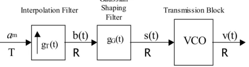
Gaussian filtered pulse stream is used to frequency modulate the carrier. First a baseband theoretical scheme of GFSK modulation can be analyzed, as shown in Figure 3.3: s(t) R Gaussian Shaping Filter gT(t) gG(t) am T Interpolation Filter R
b(t) VCO Transmission Block v(t) R
Figure 3.3 – GFSK Base-band representation.
In this scheme there are two filters to implement the digital modulation: - Interpolation Filter: gI (t) = T t rect T 2 1 , - Shaping Filter: gG (t) = 2 2 2 2 t k e k − π , where k = (2) 2 Ln B π
T is the bit period of the input stream and is equal to 1.10-6 seconds, while B is the –3 dB Band of the Gaussian shaping filter. For GFSK modulation, the BT value (bandwidth-symbol period product) used is equal to 0.5.
It is useful to consider an unique filter time response, related to the product between these two filter, and obtain:
- Total Filter: g(t) = gI (t) ⊗ gG (t) = + − − ) 2 1 ( 2 1 ( 2 1 T t k Q T t k Q T where Q(t) = e db t b
∫
+∞ − 2 2 2 1π is the Complementary Error function (Erfc). Below, the relations which regulate the GFSK modulator operation and the signal involved are shown.
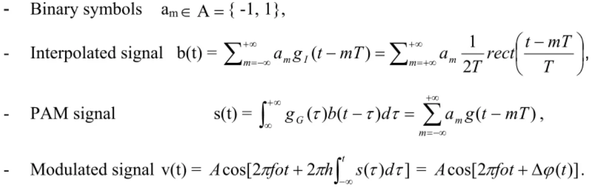
Chapter 3 Modulations for Bluetooth 29 - Binary symbols am ∈Α={ -1, 1}, - Interpolated signal b(t) = − = −
∑
∑
+∞ +∞ = ∞ + −∞ = T mT t rect T a mT t g a I m m m m 2 1 ) ( , - PAM signal s(t) = g ( )b(t )d a g(t mT) m m G − =∑
−∫
∞+∞ τ τ τ +∞=−∞ , - Modulated signal v(t) =∫
∞ − + h t s d fotAcos[2π 2π (τ) τ] = Acos[2πfot+∆ϕ(t)].
BT v alue = 0.5
[µs]
Figure 3.4 – Impulse response of total filter g(t).
Now, it is necessary to implement this analog scheme with digital filters in order to achieve a digital time filter; it should be at the maximum similar to the continuous time filter g(t). There are different ways to construct the filter, but the method used most is to sample the impulse response g(t) and the commonly duration beyond which in this case, the unit pulse response is truncated is 3T periods ( ± 1.5T from the peak).
Now, the period of sampling the signal which comes out the shaping filter is decided, and for several reasons, such as clocks which are available on the chip, a sampling period of T0 =
Mhz
13 1
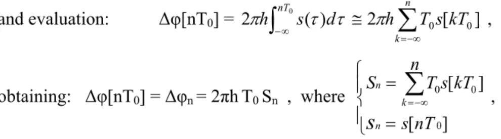
seconds is used. Consideration can be turned to the equation: ∆φ(t) =
∫
∞ − t d s h τ τ π ( ) 2 ,Chapter 3 Modulations for Bluetooth 30 and evaluation: ∆φ[nT0] =
∫
∞ − 0 ) ( 2πh nT sτ dτ 2 h n T0s[kT0] k∑
=−∞ ≅ π , obtaining: ∆φ[nT0] = ∆φn = 2πhT0 Sn , where = =∑
−∞ = ] [ ] [ 0 0 0 nT s kT s n T S n k ns
,and the Sn value is obtained through a sequential way: Sn = Sn-1 +
s
n .Thus, it is sufficient to use a simple accumulator in order to implement the digital calculation of ∆φn values.
Consideration can be given to the equivalent baseband signal of v(t), obtained by the complex envelope: cv(t) = ej∆ϕ(t) , (its module is equal to 1).
In a discrete time way cv[nT0]=cos
(
∆ϕ[nT0])
+ jsin(
∆ϕ[nT0])
,where definition can be:
[ ]
[ ]
(
(
)
)
∆ = ∆ = ] [ sin Q ] [ cos 0 0 0 0 nT nT nT nT I k k ϕ ϕ
as shown in the following logical scheme:
T
g(•)
Total Filter Accumulator
cos(2πfot) sin(2πfot) v(t) am [ ] 0 nT j e ∆ϕ [ ] ( 0) cos∆ϕnT [ ] ( 0) sin∆ϕnT D/A D/A T0 T0 T0 sn [ ] 0 nT ϕ ∆ 2πhT0
Figure 3.5 – Digital scheme of GFSK Modulator.
At this point, it is useful to briefly describe a possible hardware architecture to implement the BT-GFSK modulator. As shown in the next chapters, every filter block is implemented by a ROM in order to obtain a low complexity architecture. In this case, in accordance with the length of the filter impulse response (3T) it is necessary only to know the sequence of three data (bits), involved into filtering.
Chapter 3 Modulations for Bluetooth
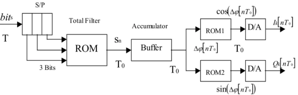
31 After the accumulator, two other ROMs can be used to obtain the sin(•) and cos(•) values. A basic digital scheme could be as shows:
T S/P Total Filter bits D/A D/A T0 T 0 Accumulator ROM Buffer ROM1 ROM2 sn 3 Bits
∆ϕ[ ]nT0 T0 [ ] ( 0) cos∆ϕnT [ ] ( 0) sin∆ϕnT
Ik[ ]nT0
Qk[ ]nT0
Figure 3.6 – Basic scheme of GFSK Modulator implementation.
3.3 BT – Enhanced Data Rate modulations
As shown above, EDR modulator follows a QAM scheme. An analysis of the signals involved follows. In this mode, complex symbols belonging to DPSK constellation points are modulated through the transmission filter, which also limits the signal frequency spectrum. Envelope fluctuations are essential since demodulation becomes increasingly difficult when the signal is amplified by a non-linear amplifier, like such as a wireless device. The instantaneous phase transitions of the DPSK signal generate a large amount of spectral splatter, which require an unreasonably large channel bandwidth. A Square Root Raised Cosine filter (SRRC) with a roll-off factor α equal to 0.4 is introduced by Enhanced Data Rate specifications, both transmission and receiving filter. This is because optimum detection is accomplished with matched filters obtaining a Raised Cosine channel filter, in order to avoid significant Inter-Symbol Interference (ISI). The frequency response of a SRRC filter follows the typical way of Raised Cosine to which is applied a square root and given by the following:
Chapter 3 Modulations for Bluetooth 32
( )
0 ; 2T 1 f 2T -1 2 1 2 cos ; 2T -1 f 0 1 + ≤ ≤ − − ≤ ≤ = elsewhere. α α α α π α T f T f H (3.5)Instead, the impulse time response of the SRRC is:
( )
(
)
(
)
otherwise 4 1 1 cos 4 1 sin ; 4 T t if 4 cos 2 1 4 sin 2 1 2 ; 0 t if 4 1 2 − + + − ± = − + + = + − = . T t T t T t T t T t t h α π α π α α π α α π π α π π α π α α (3.6) [µs] [M Hz]Figure 3.7 – SRRC filter: Frequency response and Time response.
The absolute bandwidth of the system is: B fs
2 1+α
Chapter 3 Modulations for Bluetooth
33 where fS is the frequency of transmitted symbols. In this case, fs =1/T, where T is
equal to 1 µs, so a bandwidth is obtained of B = 700 KHz.
At this point, the lowpass equivalent information-bearing signal v(t) is generated according to the following typical relation of a QAM signal:
( )
=∑
(
−)
k kht kT S t v , (3.7)( )
( )
[
k k]
k k k k k k A A j I jQS = expΦ = cos Φ + sin Φ = + . (3.8) where Sk are the complex DPSK symbols and the phase terms Φk are constants
over a symbol period T, which means that: Φ(t) = Φk,for kT≤ t ≤(K+1)T .
Now, this baseband signal modulates the frequency carrier, according to the initial scheme. Therefore a bandpass signal is obtained and transmitted, which has the following form:
( )
[
f t t]
t
s( )=Acos2π 0 +Ψ (3.9)
where Ψ(t) is the phase term that carries the information and depends on the v(t) signal. At this point, it is useful to remember that now, the phase term Ψ(t) is not constant during T period. Using trigonometric identities the transmitted signal can be split into In-phase component I(t) and Quadrature-phase component Q(t), both depending on kth symbol, where:
( )
t e ( ) A( )
t[
( )
t( )
t]
I( )
t jQ( )
t A t v( )= Ψt = cosΨ +sinΨ = + (3.10)( ) (
t f t) ( ) (
Q t f t)
I t s( )= cos 2π 0 − sin 2π 0 (3.11) where exactly:( )
(
)
( )
(
)
− = − =∑
∑
k k k k kT t h Q t Q kT t h I t IThis kind of signal has been chosen for both of EDR modulations: π/4-DQPSK and 8DPSK. Moreover, the constellation points are identical, only the phase data sequence and relative bearing information are dissimilar. In this way, transmission can be made of 2 or 3 bits per symbols unconditionally. Thus, a transmission of 3
Chapter 3 Modulations for Bluetooth
34 bits seems more advantageous, but if an error occurs during the receiver and demodulation block, more information could be lost.
π/4 – DQPSK
The modulation π/4-DQPSK (Differential Quadrature Phase Shift Keying) has been adopted by several producers of digital cellular, specially in the USA and Japan, for its spectral efficiency. In fact, this kind of modulation is a rotated version of 8-QPSK and moreover could be the superposition of two sets of 4 constellation points belong to two 4-QPSK modulations, rotated by π/4 radiant. The π/4-DQPSK is also a differential modulation. It is therefore more robust to noise, but inside the modulation block, a more complicated circuit is needed based on a sequential logic circuit; because if an error occurs during modulation at least 2 information bits would be lost.
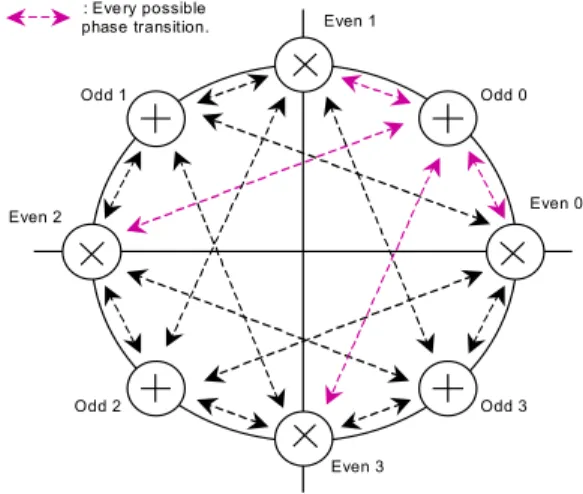
Symbol phase are alternatively selected from one of the two 4-QPSK constellations and, as result, successive symbols have a relative phase difference that is one of the four possible angle ± π/4 and ± 3π/4. In this way, the envelope fluctuation is significantly reduced, because instantaneous transitions of ± π are not permitted by the EDR specifications. As figure 3.7 shows, the two constellation sets are: {0, ± π/2, π} for even symbols and {± π/4, ± 3π/4} for odd symbols. : Eve ry possible phase transition. Even 0 Even 1 Even 2 Even 3 Odd 0 Odd 1 Odd 2 Odd 3
Chapter 3 Modulations for Bluetooth
35 For odd numbered symbols, the output signal phase is chosen from one of four possible phases of the constellation set with a + ; and for even symbols, the output signal is instead chosen from one of the other four possible phases of the constellation set by an ×. Since in every symbol period T, there are four possible changes of phase, transmission of only 2 bits of information can be made. The phase Φk for the kth symbol can be expressed as:
k k
k=Φ +∆Φ
Φ − 1 (3.12)
where Φk-1 is the phase for the (k-1)th symbol and ∆Φk is the phase transition. The
data-phase changes correspondence for the two bits of information is shown in Table 3.1. As usual, Gray coding is applied in order to reduce bit errors that could happen inside the logic circuit of transmission, reception or demodulation.
b2k-1 b2k ∆Φk 0 0 π/4 0 1 3π/4 1 1 -3π/4 1 0 -π/4 Table 3.1 − π/4-DQPSK mapping.
8DPSK
The 8DPSK (Differential Phase Shift Keying) is quite similar to π/4-DQPSK. The eight constellation points are identical and only one can be chosen as symbol phase for each symbol period T. Therefore, eight phase transitions are possible, as shown in Figure 3.8. In this way transmission can be made of three bits associated to every complex symbols. Moreover, 8DPSK also is a differential modulation. Information is therefore carried by phase changes and the relation (3.12) is still valid. Further, Gray coding is also applied and the different data-phase changes correspondence for the three bits of information is shown in Table 3.2:
Chapter 3 Modulations for Bluetooth 36 b3k-2 b3k-1 b3k ∆Φk 0 0 0 0 0 0 1 π/4 0 1 1 π/2 0 1 0 3π/4 1 1 0 π 1 1 1 -3π/4 1 0 1 -π/2 1 0 0 -π/4 : Ev ery possible phase transition f or each point. Point 0 Point 2 Point 4 Point 6 Point 1 Point 3 Point 5 Point 7
Figure 3.9 – 8DPSK constellation points. Table 3.2 − 8DPSK mapping.
As shown above, both π/4-DQPSK and 8DPSK are differential phase modulations. In this way, only the phase transition between two consecutive data symbols are of interest. Therefore, the modulated data sequence remains unvaried if a rigid rotation is applied to the constellation points. The specifications allow the choice of the initial reference symbols for the easier implementation of the modulation block. An initial reference phase of π/8 is chosen for both modulations, to be analysed in the following chapters.