70
2. AIM OF THE THESIS
Exposure to microgravity during Space flights of variable length induces a suffering of the endothelium, the cells lining all blood vessels, mostly responsible of health problems reported by astronauts and animals returning from Space. These effects are striking similar to the consequences of sedentary life, senescence and degenerative diseases on Earth, although Space flights effects are accelerated and reversible. Microgravity therefore represents a significant novel model to better understand common pathologies.
Thus, a comprehensive cell and molecular biology study is necessary to explain pathophysiological findings after Space flights in terms of variations in genome biology.
The long-term goal of the project “Molecular and cellular characterization of Space flight effects on endothelial cell function”, selected by the European Space Agency, is to characterize at a molecular level the effects of the Space flight on human microvascular endothelial cells (HMEC-1) in terms of cell senescence, DNA damage and gene expression alteration.
Within this project, my thesis work has been based on the developing of the biological and engineering conditions to get suitable samples after culturing, fixing and storing endothelial cells (ECs) inside specific bioreactors that will be send to the International Space Station.
During this preparatory phase, we aimed at testing different experimental conditions for implementation of the experiment in Space, focusing on the following issues:
71 number for seeding coverslips, culture support, medium composition.
2) testing several pre-flight incubation protocols to simulate different mission scenarios.
3) establishing a fixation and storing protocol that will allow to obtain suitable samples for subsequent experimental procedures, like nucleic acid extraction and fluorescent staining: fixative solution, working dilution, fixation time, storing solution.
All results obtained from these tests were used to write up a report for the European Space Agency, the Experiment Scientific Report (ESR). It is an official document that definitively establishes all the experimental details to implement the study in orbit.
72
3. MATERIALS AND METHODS
3.1 Cell Line
HMEC-1, Human Microvascular Endothelial Cells (CDC, Atlanta, GA USA), is an immortalized endothelial cell line obtained in 1992 by transfecting human dermal microvascular endothelial cells (HMEC) with a PBR-322-based plasmid containing the coding region for the simian virus 40 (SV-40 virus). A gene product, large T antigen, succeeded in immortalizing them and the difficulties correlated with culturing human microvascular endothelial cells were overcome. HMEC-1 retains the morphologic, phenotypic, and functional characteristics of normal human microvascular endothelial cells, but grow to densities three to seven times higher and require much less stringent growth medium.
They express cell-surface molecules typically associated with endothelial cells, like CD31 and CD36, and adhesion molecules CD44 and ICAM-1.
Before seeding HMEC-1 cells, we always coat the surface of dishes and coverslips with 2% gelatin for 20 minutes at Room Temperature, in order to enhance their adhesion capacity.
HMEC-1 are cultured in MCDB 131 medium (SIGMA) supplemented with: Hydrocortisone 1 µg/ml EGF 10 ng/ml Sodium bicarbonate 1mM FBS 10% Penicillin 1 U/ml Streptomycin 1 µg/ml
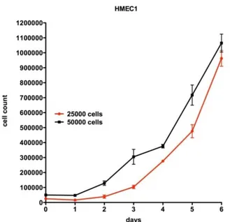
73 However, when incubating seeded coverslips in the culture chamber of the bioreactor, MCDB 131 medium is additionally supplemented with Hepes (20 mM), which is particularly good at maintaining physiological pH despite changes in carbon dioxide concentration. In fact, the inner chamber of such devices is totally isolated by external environment, so that gas exchanges are not allowed. As we can see from the HMEC-1 growth curve (Fig. 15), under this culturing conditions, cells grow exponentially and their doubling time lasts a little longer than 24 hours.
3.2 Cell culture support
Growing cells inside the bioreactor requires appropriate culture supports; in fact they have to be resistant to mechanical stress and quite flexible, so they won’t break under the strong acceleration the bioreactors will be exposed to, when
Figure 15. HMEC-1 growth curves, starting from
25.000 cells (red) and 50.000 (black).
74 launched to the International Space Station. Coverslips dimensions have to be 10.5x22 mm to fit in the bioreactors Culture Chamber.
In addition, they have to be suitable for subsequent application, such as fluorescent staining.
Taking into account all these requirements, two different kind of plastic coverslips were tested for HMEC-1 seeding: Thermanox Coverslips (Nunc 174934) and IBIDI COC (Cyclic Olefin Copolymer) plastic coverslips.
Nunc Thermanox is a special polymer which is highly resistant to most chemicals, flexible and transparent. It can also withstand high temperatures, from -70 to +150°C. Although Thermanox Coverslips are culture-treated on one side for enhanced cell attachment and growth, their performances improve by coating them with 2% gelatin. They are sold as sterile items.
However, this type of culture support had a great limitation for our studies that is their unsuitability for fluorescent microscopy.
For this reason, we selected IBIDI COC plastic for its excellent optical performance, good cell adhesion properties and flexibility. Coverslips made out of IBIDI plastic are coated with 2% gelatin as well. They are rinse in 96% Ethanol and keep under the UV-light for 15 minutes.
3.3 The Bioreactor
Cell growing tests are performed inside a specific bioreactor developed by Kayser Italia S.r.l., which is able to fulfill a scientific protocol based on automated culturing and fixing of cells seeded on a plastic coverslip.
It is constituted by two different parts that have specific functions: a passive unit and an active one. The former is represented by the main body of the hardware, with the culture support and the lateral cover; on this lateral side there is the Culture Chamber (CC), where the seeded coverslips are placed on the specific
75 support. The latter is the Release System unit, which is formed by a plate assembled with bowls and springs that drive the fluid motion inside the Experimental Unit (EU). Although pistons and valves are passive elements, they are triggered by the Release System. As the liquid is set in motion, before entering the CC, it encounters a grid that avoids turbulent flows that may cause cell detachment from the coverslip surface.
Silicon gaskets guarantee the sterile CC isolation from external environment and prevent different fluids to mix with each other.
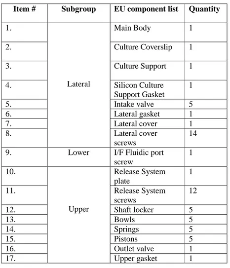
The following table (Tab. 1) lists all the components the bioreactor consists of.
.
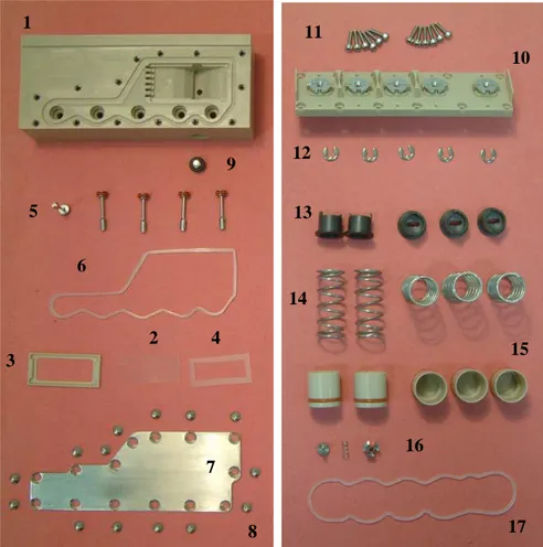
All the numbered items from the table 1 are also shown in the figure below (Fig. 16).
Item # Subgroup EU component list Quantity
1. Lateral Main Body 1 2. Culture Coverslip 1 3. Culture Support 1 4. Silicon Culture Support Gasket 1 5. Intake valve 5 6. Lateral gasket 1 7. Lateral cover 1 8. Lateral cover screws 14 9. Lower I/F Fluidic port
screw 1 10. Upper Release System plate 1 11. Release System screws 12 12. Shaft locker 5 13. Bowls 5 14. Springs 5 15. Pistons 5 16. Outlet valve 1 17. Upper gasket 1
76
The concept of fluid exchange system has been developed to allow automated cell culture inside a bioreactor, as shown in Fig. 17. The actions performed by the fluidic system are led by preloaded spring actuators activated by Shape Memory Alloy (SMA). Such mechanism releases the plungers inward displacing the fluids contained into the chemical reservoirs towards the Culture Chamber. A manifold channel connect each reservoir to the CC so that cells are exposed to culture medium (green), washing buffer (blue) or fixative (red) as needed, with displacement of exhausted medium (yellow). This actions will be totally under electronic control once on board of the International Space Station.
Flow rates of medium and fixative have been carefully evaluated in order to avoid the onset of shear stress on the cells. They should not exceed 0.65 ml/sec.
1 3 6 5 9 4 2 7 8 14 15 16 17 13 12 11 10
77
Figure 17. Schematic fluidic concept of the hardware. Culture medium shown
in green, washing buffer in blue, fixative in red. Exhausted solutions are in yellow.
What comes next is an accurate description of all the procedures required to assemble the bioreactor, fill its inner channels with appropriate solutions, prepare the Culture Chamber and manually activate the fluid displacement, schematized above.
3.3.1 Release System unit Bowl assembly
The Release System unit is the only part of the hardware that doesn’t need sterilization, so it is assembled before all else as follows:
1. Fix a double-sided adhesive tape on a flat surface and remove the protection lip.
2. Place a Bowl on the double-sided adhesive tape. 3. Insert the spring into the Bowl.
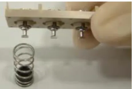
78 4. Place the Release System Plate so that the Shaft key matches with the
Bowl’s groove (Fig.18).
5. Press downward the Release System Plate.
6. Keep pressing the Release System while rotating anticlockwise the Shaft with the Parallel Tip Screwdriver. The key gets orthogonal to the Release Unit’s longitudinal axis.
7. Slowly release the Release System Unit Plate.
8. Repeat the actions 3-7 to complete the Bowls assembling procedure.
3.3.2 Main Body pre-assembly
This are the procedures that precede the autoclave sterilization of the Main Body:
1. Lubricate the Piston O-rings with a swab soaked in vaseline grease.
2. Using the Piston remover tool, move the piston up and down to lubricate the reservoir walls.
3. Leave the pistons protruding from the Main Body.
4. To position the pistons properly, overturn the body and push it downward so that the five pistons move inwards at the required level.
5. Place the Upper gasket into its groove. 6. Place the Lateral gasket into its groove.
Figure 18. Placing the Release
79
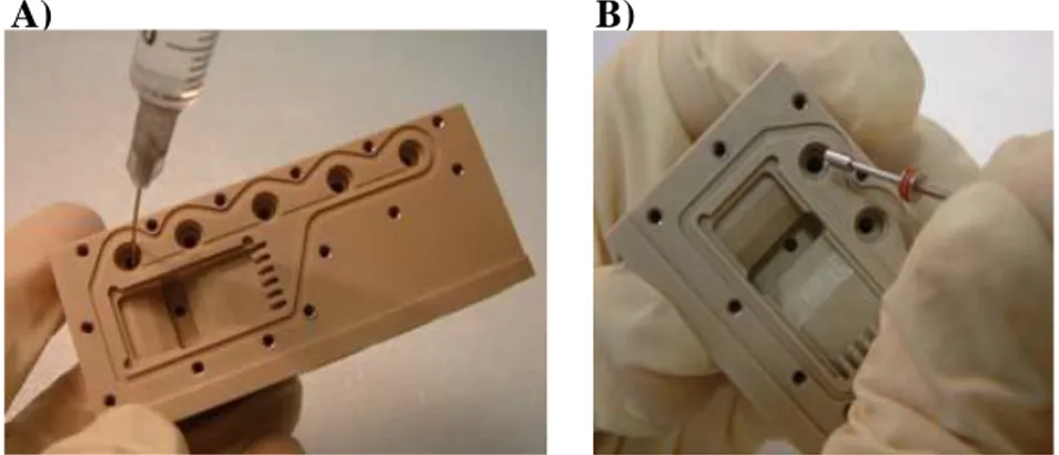
3.3.3 Reservoirs filling procedure
Once the Main Body has been sterilized together with other components, it is ready to be filled and completely assembled, working under a laminar flow hood. The five Reservoirs, namely A, B, C, D and E (Fig.19) are identified so that the A reservoir is the farthest from the Culture Chamber and the E reservoir is at the opposite side. Each of them have to be filled with a specific solution, so five different fluid injections can be performed. Reservoir A is the first one that will be activated.
A general description of the filling procedures follows:
1. Place the autoclave bags under a laminar flow bench and open them. 2. Load a syringe with the required liquid volume, removing possible air
bubbles that may cause whirls.
3. Keep the Main Body upside down so that the CC is visible to the operator. 4. With regard to the reservoir E, lean the pre-assembled Main Body and
keep it in the same position till the E reservoir get filled (Fig. 20.A).
5. Take the Inlet Valve with the proper tool and push it into the filling hole (Fig. 20.B).
A B C D E
Figure 19. Lateral view of an EU; black arrows
indicate the 5 Reservoirs, yellow ones show the fluid pathway.
80 6. With regard to the reservoirs A, B, C and D lean the pre-assembled Main
Body and keep it in the same position till the reservoir get filled.
7. Take the Intlet Valve with the proper tool and push it into the filling hole. 8. Repeat actions 7-8 so that the four reservoirs get filled.
3.3.4 Release Unit System integration
At this point, we need to attach the Release System plate to the Main Body, whose Reservoirs have been previously filled.
1. Take the Release Unit System as previously assembled and place it over the Main Body.
2. Check the matching between the reservoirs and the Bowls. 3. Gently, insert the Release Unit System inward the body.
4. Fix the Release Unit System using the Soked head cap screw starting from one of the Release Unit System plate corners, tighten the screw with the torque screwdriver ; then, tighten the diametrically opposite screw.
5. Repeat the action 4 five times so that all the screws are properly screwed.
A) B)
Figure 20. Filling Reservoir E with a syringe (A) and closing it with an Inlet
81 6. Check that the Inlet Valves are closed. In the case of liquid excess within the reservoirs, the Release Unit System tightening can cause overpressure and open the Inlet Valves.
3.3.5 Culture Chamber filling procedure and assembling
Filling the Culture Chamber with medium is the last thing left to complete the bioreactor preparation. Then, this inner space is sealed by fixing the lateral metallic cover and the hardware is ready be incubated at 37°C.
1. Rest the Main Body on the bench floor so that the CC looks upward. 2. Check the Lateral Gasket, if necessary fix it into the dedicated groove (this
action has not a direct impact on the filling procedure, on the other hand it makes easier the next Lateral Cover assembling reducing the Main Body handling while the CC is open).
3. Load the syringe with the required liquid volume.
4. Inject the liquid within the CC so that the whole volume of liquid loaded exceeds the required volume. This is due to avoid air bubbles while the culture support system is set. Inject the liquid within the fluidic path and the Exit Valves wells.
5. Place the Culture Support in the dedicated housing. 6. Place the Coverslip into the culture support frame. 7. Place the silicone gasket on the coverslip support.
8. Gently lay down the lateral cover in the corresponding frame and fix it using Pozidriv Cross recessed flat head screws. Starting from one of the lateral cover corners, tighten the screw with the torque screwdriver. Then, tighten the diametrically opposite screw. Repeat till all the screws get properly screwed.
82
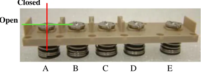
3.3.6 Manual activation of the Bioreactor
The instructions below show how to perform the activation manually; each fluid injection is leaded by the Release System unit. The activation takes place following the order of reservoirs: i.e. the Reservoir “A” is the first one activated, the “E” reservoir is the last one.
The activation of the first Reservoir represents the beginning of the experiment. 1. Insert the parallel tip Screwdriver into the Shaft's groove and make it turn
in a clockwise manner, as shown in Fig. 21. When the Shaft's groove is parallel to the body axis the Bowl is released pushing the piston inward the body.
2. Repeat the step 1 four times to perform all the actions.
By rotating the Shafts, Springs and Bowls are released and their force acts on the Pistons below. They compress the fluid inside the Reservoirs, making the Inlet Valves open. In this way, solutions can flow through the delta fluidic pathway (shown in Fig. 19) to the Culture Chamber.
Once on board of the ISS, all the fluid injections will be performed under electronic control.
A B C D E
Closed
Open
Figure 21. Bioreactor manual activation of Shaft A; open (green) and
83
3.4 Cell growth inside the Bioreactor
About 24 hours before assembling the bioreactor, HMEC-1 cells are seeded on 2% gelatin-coated and uncoated Coverslips. In this way, cells have plenty of time to attach to the substrate, before the coverslip is moved in the bioreactor chamber. Different seeding tests have been performed to select the most suitable Coverslip and to establish an optimal starting cell number.
The next day, the Experimental Unit is assembled under the laminar flow hood, as described in the paragraphs above: the CC and the Reservoirs are filled, the coverslip is inserted into its specific support, the Release System is attached to the Main Body and the lateral plate closes the chamber.
A general order of filling is schematized below:
Working in sterile conditions is fundamental in order to prevent possible contamination, that may occur during the long-term incubation of HMEC-1 inside the bioreactor.
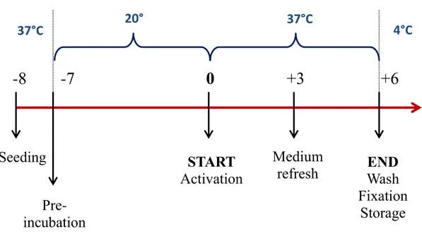
In fact, besides the 6 days planned for the experiment in microgravity, we have to take into account the severe conditions imposed by the mission scenario too. Therefore, there is the need to perform low-temperature incubation, which may simulate the time gap immediately before and after the launch.
So the culturing protocol requires a first incubation of the EUs at 18°C or 20°C for up to 7 days, placing 37°C-heated “ice bricks” along with the them inside a polystyrene box. This could be the time required for pre-launch activities, plus 2 days for orbital flight and 2 days for a possible delay too.
A B C D E
84 After this pre-incubation, the bioreactors are transferred at 37°C and their activation is performed; this means that the first Shaft (A) is rotated and the 6-day experiment begins. Another medium refresh is required 3 days later (Shaft B). On the sixth day, the experiment has come to an end and cells have to be fixed and stored at 4°C. The last three Shafts (C,D and E) are rotated in succession. The earlier described sequence of events is summarized in the figure below, which represents the experimental timeline.
-8 -7 0 +3 +6
Seeding
START
Activation
END
Wash
Fixation
Storage
Medium
refresh
Pre-incubation
37°C 20° 37°C 4°CFigure 22. Timeline of the whole six-day experiment inside the bioreactor, considering a
85
3.5 Fixing and storing protocol
The end of the experiment inside the bioreactor is established by cell fixation. In this way, cells can be stored until they are recovered on Earth to be subjected to further analysis.
A common reagent for cell fixation is Paraformaldehyde, a cross-linking chemical that preserves cell structure in an optimal way and it is a good fixation method for cells labeled with fluorescent stains.
But due to safety reasons on board of the ISS, Paraformaldehyde must be replaced by non-harmful chemicals. Despite this, during the preparatory phase, 4% Paraformaldehyde can be used as a gold standard fixative, to be compared with the performances of the other two commercial reagents: NotoxHisto (EarthSafe Industries, IL USA) and RNAprotect Cell Reagent (Qiagen).
Samples have been subjected to many different tests in order to select the most suitable fixation and storing protocols for their further processing.
In fact, depending on the application the sample is committed to, we had to establish which fixation protocol was the best for that purpose.
Different solutions of NotoxHisto were tested to fix HMEC-1, including the non-diluted one :
NotoxHisto solutions
Undiluted (recommended by the producer)
1:2 in 1X PBS
1:5 in 1X PBS
86 These solutions were compared to each other to decide which one led to the best result.
Analogously, RNA Protect was tested as indicated below:
RNA Protect solutions
Undiluted
6:1 (as recommended in its handbook) in culture medium
1:6 in culture medium
1:6 in 1X PBS
Cells are fixed at 37°C, because it is the incubation temperature of the bioreactors on board of the ISS. Moreover, fixation time has been extended to 1 hour to be sure that cells are fixed.
Fixed samples then are stored at 4°C. Possible storing solutions are 1X PBS, NotoxHisto and RNA Protect.
A short description of the main features of the two reagents follows.
3.5.1 NotoxHisto
NotoxHisto from EarthSafe Industries is a new commercial substitute of formalin that uses a complex aldehyde (possibly di-aldehyde glucose) in about 70% alcohol with antiseptic and antifungal agents; so it produces a combination of aldehyde- and alcohol-type fixation patterns.
87 NotoxHisto is a fixative that is non-carcinogenic, non-noxious, non-corrosive and has no heavy metals nor chloride ions. This fixative allows to perform all the tasks previously performed with formalin, without the risk and the high cost of disposal. Unlike formaldehyde, antigenic sites and DNA are unaltered.
All sizes of specimens ranging from small sections to whole organs can be fixed in NotoxHisto. Due to a unique blend of protein modifiers and stabilizers, it has the ability to both fix and preserve tissue. It can be used without change in processing or staining protocols.
Although the producer assures that there is no need of pre-mixing or diluting and that the fixative is ready-to-use, its performances in fluorescent staining are remarkably enhanced by diluting NotoxHisto in 1X PBS.
3.5.2 RNAprotect Cell Reagent
The RNAprotect Cell Reagent is a stabilization solution for reliable gene expression analysis which provides a complete stabilization and purification of total RNA from sorted or cultured cells. RNA in cells is immediately stabilized using RNAprotect Cell Reagent and then it can be rapidly purified.
This reagent uses a novel patent-pending technology to immediately stabilize transcript levels during storage of cell samples.
With other technologies, it is necessary to wash or process the cells (e.g., trypsin treatment) prior to adding RNA stabilization reagent. However, changes in gene expression may occur during the washing or processing steps.
In contrast, RNAprotect Cell Reagent can be added directly to cells in culture medium or buffer, providing instantaneous RNA stabilization. After stabilization, cells can be conveniently stored with the cellular RNA remaining intact and undegraded. RNAprotect Cell Reagent also enables stabilization of DNA, providing simultaneous stabilization of RNA and DNA in the same cell sample.
88
3.6 Cell viability and counting
To establish a suitable culturing protocol, we need to know how many cells there are on the surface of the Coverslips after different incubation conditions.
So, not always there is the need to perform the whole experiment inside the bioreactor, but we are interested in determining cell number and viability by manual counting with Burker Chamber.
PBS-washed cells are trypsinized for 5 minutes at 37°C and then stained with the vital dye Trypan Blue, diluted 1:2. Cells with a damaged membrane are stained in blue and considered dead.
3.7 Genomic DNA extraction
Genomic DNA extraction was performed using the DNeasy Blood&Tissue Kit (Qiagen) which is suitable for smaller samples (from 100 cells up to 5x10⁶ cells). We started with circa 90.000 cells form one 90% confluent Thermanox Coverslip fixed in 1:6 RNA Protect and stored in the same solution at 4°C.
1. 30’’ wash with 1 ml of 1X PBS 2. Scrape the coverslip with pipette tip
3. Centrifuge at 300 xg for 5’ and resuspend pellet in 200 µl of 1X PBS 4. incubation with 20 µl of RNase A (20 mg/ml), 2’at RT
5. Add 20 µl of Proteinase K and 200 µl of AL buffer 6. 10’’ vortex
7. 10’ incubation at 70°C 8. Add 200 µl 96% Ethanol 9. 10’’ vortex
89 10. Load the column
11. Centrifuge at 6000 xg for 1’ and discard the flow-through 12. Add 500 µl of AW1 buffer
13. Centrifuge at 6000 xg for 1’ and discard the flow-through 14. Add 500 µl of AW2 buffer
15. Centrifuge at 20000 xg for 3’ and discard the flow-through 16. First elution with 100 µl of AE buffer, 1’ at RT
17. Centrifuge at 6000 xg for 1’
18. Second elution with 100 µl of AE buffer, 1’ at RT 19. Centrifuge at 6000 xg for 1’
20. Make aliquots and store at -20°C.
3.7.1 NANODROP concentration measurements
After the purification, we quantified the DNA concentration by using NanoView™ Spectrophotometer (GE Healthcare) as follows:
1. Rinse with distilled water when prompted to load water sample (clean off top and bottom afterward each sample)
2. Blank with 2 µl of buffer (whatever DNA was eluded with) 3. Run 2 µl of each sample, reading at a wavelength of 260 nm. 4. After each sample rinse with 2 µl of buffer
90
3.7.2 Agarose gel electrophoresis
Now that the amount of genomic DNA has been determined, it is possible to run an agarose gel to evaluate its integrity and quality.
Since we need to resolve such high-weight fragments, a low agarose concentration is appropriate. In fact, the agarose percentage used to prepare the gel is 0,6%, which means that 0,6 g of powder are dissolved in 100 ml of 1X TBE buffer, in addition with Ethidium Bromide diluted 1:1000. When the agarose is solidified, the gel is placed in the electrophoresis unit and the box is filled with 1X TBE buffer. A molecular weight ladder is loaded in the first lane of the gel, so it will help monitoring the run. The additional wells are loaded with the samples diluted in 6x Orange G loading dye, which runs faster than genomic DNA and doesn’t interfere with its visualization. Voltage is set at 80 mV and the running time is of 45 minutes. Solutions 1X TBE Tris base 90 mM Boric acid 90 mM EDTA 2 mM 6X Orange G Tris-HCl (pH 7.6) 10 mM Orange G 0.15% Glycerol 60% EDTA. 60 mM
91
3.8 Total RNA extraction
Total RNA extraction was performed using the RNeasy Mini Kit (Qiagen).
We started with circa 90.000 cells from one Thermanox Coverslip at 90% confluency. Cells were fixed in 1:6 RNA Protect (Qiagen) in 1X PBS, and stored in the same solution at 4°C.
- 30’’ wash in 1X PBS (1 ml)
- Add 350 µl of RA1 + 3,5 µl β-mercaptoethanol - Scrape the coverslip with pipette tip
- Load the lysate on the column
- Centrifuge at 11000 xg for 1’, recover the flow through and discard the column
- Add 350 µl of 70% Ethanol - Load a fresh column
- Centrifuge at 11000 xg for 30’’ and discard the flow-through - Add 350 µl of buffer MDB
- Centrifuge at 11000 xg for 1’ and discard the flow-through - incubate the column with rDNase, 15’at RT
- Add 200 µl of buffer RA2
- Centrifuge at 11000 xg for 30’’ and discard the flow-through - Add 600 µl of buffer RA3 (with 70% Ethanol)
- Centrifuge at 11000 xg for 30’’ and discard the flow-through - Add 250 µl of buffer RA3
- Centrifuge at 11000 xg for 2’ and discard the flow-through - First elution with 30 µl of water
- Centrifuge at 11000 xg for 1’ - Second elution with 20 µl of water - Centrifuge at 11000 xg for 1’ - Make aliquots and store at -80°C.
92
3.8.1 NANODROP concentration measurements
After the purification, we quantified the RNA concentration by using NanoView™ Spectrophotometer (GE Healthcare) as follows:
1. Rinse with distilled water when prompted to load water sample (clean off top and bottom afterward each sample)
2. Blank with 2 µl of buffer (whatever DNA was eluded with)
3. Run 2 µl of each sample. Readings are taken at a wavelength of 260 nm also in this case.
4. After each sample rinse with 2 µl of buffer. 5. Clean with distilled water after use.
3.8.2 Agarose gel electrophoresis
Now that the amount of the total RNA has been determined, it is possible to run an agarose gel to evaluate its integrity and quality.
The agarose percentage used to prepare the gel is 2%, which means that 2 g of powder are dissolved in 100 ml of 1X TBE buffer, in addition with Ethidium Bromide diluted 1:1000. When the agarose is solidified, the gel is placed in the electrophoresis unit and the box is filled with 1X TBE buffer. Wells are loaded with the samples diluted in 6x Loading Buffer; a molecular weight ladder is not needed. Voltage is set at 150 mV and the running time is of 5 minutes.
Solutions
1X TBE
93 Boric acid 90 mM EDTA 2 mM Loading Buffer Sucrose 40% Bromophenol blue 0,25% Xylene cyanol 0,25%
3.9 Morphological analysis
In order to evaluate the general quality of the fluorescent staining and the integrity of cytoskeleton architecture after using different fixative solutions, fluorescent immunocytochemistry was performed on IBIDI Coverslips-grown cells.
Samples have been stored in 1X PBS at 4°C for different periods of time before being subjected to the following procedure.
In this way, we could also check the antigen preservation after storing the samples up to 150 days. The Actin cytoskeleton was stained with Phalloidin and myosin with the specific monoclonal antibody.
1. Wash in 1X PBS
2. Incubate for 3’ in 0,2% Triton at RT 3. Wash in 1X PBS for 5’, repeat 3 times 4. Incubate 1 h at 37°C in 10% BSA
5. Incubate 1 h at 37°C with primary antibody solution 6. Wash in 1X PBS for 5’, repeat 3 times
94 8. Wash in 1X PBS for 10’, repeat twice
9. Incubate for 10’ with DAPI diluted 1:1000 in 1X PBS at RT
10. Mount the IBIDI Coverslips on slides using Aqua Poly-Mount (Polysciences Inc.).
11. Store in the dark at 4°C.
Solutions
10% BSA
BSA powder 1 g
1X PBS 10 ml
Primary anibody solution
Primary antibody appropriate dilution
1% BSA 500 µl
Secondary anibody solution
Secondary antibody appropriate dilution
1% BSA 500 µl Phalloidin 488 (Cytoskeleton) solution Phalloidin 488 3,5 µl 1% BSA 500 µl Phalloidin-Atto 550 (Sigma-Aldrich) solution Phalloidin-Atto 550 10 µl 1% BSA 1 ml
95 Images were taken using a Nikon Ti fluorescent microscope and, after deconvolution, stacks were visualized using Maximum Intensity Projection. In this way the contamination of out-of-focus contributions is minimized.
3.9.1 Reagents
The following reagent have been used for the staining of the cytoskeleton:
Phalloidin 488 (Cytoskeleton Inc., # PHDG1-A):. The fungal toxin Phalloidin has been labeled with a proprietary green fluorescent dye which allows it to be used to stain actin filaments in tissue cultured cells and tissue sections and cell-free preparations. Phalloidin has been found to bind only to polymeric and oligomeric forms of actin, and not to monomeric actin. Acti-stain™ 488 phalloidin-labeled actin filaments retain many functional characteristics of unlabeled actin including their ability to interact with myosin.
Palloidin-Atto 550 (Sigma-Aldrich, # 19083): Atto 550 is a new label characterized by a high photostability, with high molecular absorption (120.000) and quantum yield (0.80) as well as sufficient stoke’s shift (excitation maximum 554 nm, emission maximum 576 nm).
The dissociation constant of the actin-phalloidin complex has been determined to be on the order of 3 x 10⁻⁸. The dilution used is 1:100.
Phospho-Mysosin Light Chain 2 Antibody (Cell Signaling Technology, #3674): Phospho-Myosin Light Chain 2 (Thr18/Ser19) Antibody detects endogenous levels of myosin light chain 2 only when dually phosphorylated at Thr18 and Ser19. This polyclonal antibody has been produced by immunizing rabits with a synthetic phosphopeptide corresponding to residues surrounding
96 Thr18/Ser19 of human myosin light chain 2. Antibodies have been purified by protein A and peptide affinity chromatography. The dilution used is 1:200 for immunocytochemistry.
Alexa Fluor® 488 Goat Anti-Rabbit IgG (Invitrogen, # A11008): Alexa Fluor® 488 Goat Anti-Rabbit IgG (H+L) is labeled with our bright, photostable, green-fluorescent Alexa Fluor 488 dye. It is prepared from affinity-purified antibodies that react with IgG heavy chains and all classes of immunoglobulin light chains from rabbit. To minimize cross-reactivity, it has been adsorbed against human IgG, human serum, mouse IgG, mouse serum and bovine serum.
DAPI (Sigma-Aldrich, #D9542): DAPI is a blue fluorescent nucleic acid stain that preferentially stains double-stranded DNA (dsDNA). It attaches to AT clusters in the DNA minor groove having one molecule of dye for each 3 base-pairs. Binding of DAPI to dsDNA produces an approximate 20-fold fluorescence enhancement. The fluorescence is directly proportional to the amount of DNA present, with emission maximum at ~460nm. The dilution used is 1:1000.