4 Application
The application shown in this chapter has the objective to pick up and release a sphere using capillary forces and to obtain information about this process. A system made up of two syringes has been realized: the first syringe is used for the picking up and the second one for the releasing. The images acquired during the process by the using of two cameras have been analysed to measure the geometry of meniscus.
4.1 Experimental layout
To implement the tests, the components reported below and a control software have been employed. The almost static analysis requires accurate movements between the sphere and the gripper.
4.1.1 Components
Various components have been employed:
1. two syringes type 801RN made by Hamilton (Figure 1a): one for oil (S1), one for water (S2). The upper component of the syringe body is built in aluminium and the lower in glass. The needle shape is reported in Figure 1b. Each syringe has a capacity of 10 µl;
a
b
Figure 1 Microliter Syringes (a) and the shape of the needle (b)
2. the liquids in use for this experimentation are mineral oil and demineralised water. The surface tensions are 0.02 Nm-1 for the oil and 0.073 Nm-1 for the water;
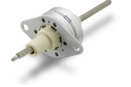
3. a linear stepper motor made by Portescap (Figure 2) controlled by a PIC 16F917;
Figure 2 Portescap linear stepper motor
4. a three axes micropositioner made by MICOS (Figure 3). This positioner has a working range of 25x25x10 mm and a bi-directional repeatability precision of 2 µm;
Figure 3 Micos MT40
5. various glass spheres with radius between 0.4 mm and 0.6 mm. The mean sphere weight is 0.02 mN ;
6. a polished aluminium plate with some holes that represent the slots for the spheres; 7. two CCD cameras optically amplified via macro lenses;
8. a telecentric illumination system;
9. various support components: a support for the syringes, two supports for the cameras;
4.1.2 Layout
The layout of the system has been chosen, after some attempts, considering that the objective is to capture sharp images: the position of the cameras, the lighting conditions, the camera parameters and the work sequences have been varied.
Figure 4, Figure 5, and Figures 6 represent the chosen layout. The purpose is to control what happens during the picking process and the releasing one. Each CCD camera focuses on a narrow field in order to monitor one syringe only. The camera A captures the video with back lighting because it is used to acquire sharp images, while camera B works with natural light and it is used to monitor the second needle. The three d.o.f. micropositioner moves the aluminium plate and positions it with reference to the syringes group.
Figure 4 Layout scheme Stepper Motor Syringe S1 Syringe S2 Al. Plane Micro positioner
X
Z
Y
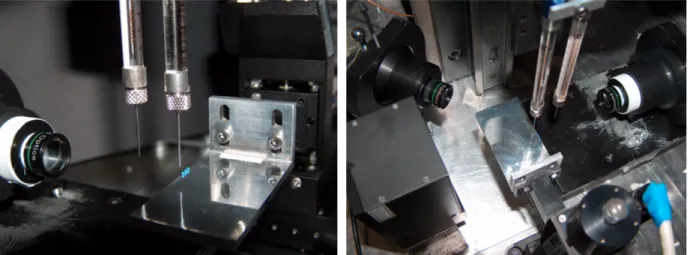
Figure 6a and Figure 6b Detailed views of the experimental layout
4.1.3 Control
To get comparable data, the experiments have to be quick enough to limit evaporation of the releasing liquid (water). This problem has been solved developing a visual basic program able to automate tests and so to realize very quick experiments. The developed programs send the motion instructions to the micropositioner and the required commands to the stepper motor connected to the syringes using a RS232 connection and a PIC. In Figure 7 the control interface of the program for the picking and releasing tests is represented. See Appendix C for the listing of the programs.
4.2 Deposition tests
The volume of the drops deposited by the syringes depends on the initial liquid quantity as well as the distance between the edge of the needle and the plane. For the experiments the volume must be about the same for each test, so it is necessary to determine the steps that the stepper motor must execute between two trials to release the same initial quantity. Some deposition tests have been done to valuate this, varying initial and intermediate steps.
Moreover, to valuate contact angles of the liquids on the surfaces involved in the experiments, three series of ten depositions for each liquid-component couple (water-aluminium, water-glass, oil-glass) have been done.
These tests, in addition to the stepper motor control, simply require to the micropositioner two movements along the z axis (up and down) and a movement along the y axis for each placed drop.
The camera A focuses on the closest needle so it captures all the deposition process (Figure 8).
a
b
c
Figure 8 Deposition tests: water on aluminium (a), water on glass (b), oil on glass (c)
Images have been analysed by a imaging processing tool to measure volumes and contact angles (see par. 5.1.6).
4.3 Picking and releasing tests
Manipulation tests have been done as a sequence of picking and releasing of four glass spheres initially positioned in conic holes obtained on the plate. The two syringes have been filled with two different liquids: one with demineralised water and the other with mineral oil.
The proposed procedure for micro-manipulation (Figure 9 and Figure 10) starts with the deposition by syringe S2 of a water drop nearby the edge of the aluminium plane moved along z axis by the micropositioner (shift 1 in Figure 9). Then the plane is shifted along y axis and after along x axis (shifts 2 and 3). Consequently the syringe S1 is in the exact position to grab the sphere down below with another movement along z (shift 4). When the oil drop generated by the syringe touch the sphere, it forms a liquid bridge, so capillary force is generated on the object. When the plane is lowered (shift 5) the sphere is picked up by means of the capillary force. The plane returns to the previous y coordinate (shift 6) and the sphere is held above the formerly placed drop. Now the plane is lifted (shift 7) and the water forms another liquid bridge between the substrate and the object, therefore another capillary force is also generated. If this force added to gravity force is sufficient to win picking force, when the plane is lowered again, the upper liquid bridge will collapse and the sphere will lay on the substrate. In the end the plane moves along the x axis and returns to the initial position. In order to repeat the process for the other spheres prepared, the micropositioner shifts along y axis of a distance equal to the distance between the spheres and the stepper motor pushes the piston to generate others drops from the syringes.
S2
S1
S2
S1
S1
S2
Figure 10 Proposed procedure for manipulation
In addition to described ones, others pick and release experiments have been done using a reduced value of the speed of the aluminium plane during releasing task. These tests have been useful to approximate static conditions and to examine the releasing mechanism closely.
In all these tests the picking and releasing phases are captured by camera A, while camera B functions as control of deposition syringe S2 .