Universita’ degli Studi di Pisa Facolta’ di Ingegneria
Centro Interdipartimentale di Ricerca “Enrico Piaggio”
Tesi di laurea in Ingegneria dell’Automazione
A model-based approach to control over
packet-switching networks, with application to
Industrial Ethernet
RELAZIONE SINTETICA
Relatori:
Ch.mo Prof. A. Bicchi Ch.mo Prof. M. Innocenti Dott. Ing. S. Falasca
Candidato:
Gaetano Lorefice
Sommario
Negli ultimi anni i sistemi di controllo su rete (Networked Control Systems, (NCS)) hanno visto un crescente interesse grazie ai numerosi vantaggi che offrono, quali la facilit`a di installazione e manutenzione, l’ampia flessibilit`a e i costi contenuti. In ambiente industriale le reti basate su Ethernet si stanno sempre pi`u diffondendo (Industrial Ethernet Networks) e sebbene il protocollo Ethernet abbia tanti vantag-gi, esiste un ampio margine di miglioramento nel suo utilizzo per scopi di controllo, basti vedere che molte applicazioni non sfruttano al meglio la grande dimensione del campo dati di un pacchetto. In questo lavoro sar`a proposto un innovativo schema di controllo che tenta di migliorare l’uso delle reti industriali basate su Ethernet (Industrial Ethernet Networks) in applicazioni di controllo. Questo approccio mod-ifica il paradigma convenzionale di controllo—ben consono a reti di comunicazione circuit-switching—e lo adatta alla natura packet-switching di Ethernet. La tecnica proposta, chiamata Packet-Based Control (PBC), consente al controllore di spedire pi´u valori utili di controllo in un singolo pacchetto in modo tale da sfruttare al meglio la sua grande dimensione. Inoltre, `e possibile sfruttare queste informazioni per ridurre il numero di pacchetti per lo specifico task di controllo, fornendo cos`ı un migliore trade-off tra la banda passante di rete utile e le prestazioni. In questo lavoro di tesi ´e stata fatta una formulazione matematica ed ´e stato progettato un simula-tore in ambiente Matlab/Simulink per l’implementazione del controllo su rete. La strategia di controllo ´e stata applicata ad un case study proposto da un’importante azienda nel settore dell’automazione; i risultati ottenuti dalle simulazioni mostrano l’efficacia e la praticit´a del metodo, applicato ad un problema industriale reale.
Abstract
In recent years Networked Control Systems (NCS) have received considerable at-tention. The interest for NCS is motivated by many benefits that they offer, such as the easiness of maintenance and installation, their large flexibility and low cost. Ethernet-based networks are becoming more common in industrial environments (Industrial Ethernet Networks). Although Ethernet has many advantages, there is room for improvement in its usage for control purposes, for example, many control applications do not take advantage of the large size of the data field of a packet. In this work, a novel scheme of control is proposed to improve the effectiveness of Industrial Ethernet Networks for control applications. Such a control approach modifies the conventional control design paradigm—well suited for circuit-switching communication networks—and adapts it to the packet-switching nature of Ethernet. The proposed technique, named ”Packet-Based Control” (PBC), enables the con-troller to send more useful control values within a single packet in order to exploit the large packet size. Moreover, it is possible to use the availability of more in-formation to send/receive less packets for a specific control task, thus providing for a better trade-off between effective bandwidth and control performance. The control strategy is applied to a realistic scenario and in particular, to a case study proposed by an important Industrial Automation provider. A mathematical for-malization and a network control simulator in Matlab/Simulink environment are designed. Results show the effectiveness and practicality of the approach as applied to a realistic industrial testbed.
Networked Control Systems (NCS) have become a widely considered re- Introduction
search topic. A Networked Control System is a system where sensors, ac-tuators and controllers are spatially distributed and exchange information through a shared digital finite capacity channel, thus the main difference between classical feedback control systems and NCS is the presence of a communication channel between sensors, controllers and actuators whereas in classical control loop the interconnection between nodes occurs directly by means of dedicated wiring. The use of the network as a communication medium makes the traditional control theory not always applicable. In this context, the mechanism of communicating information plays an important role on the stability and performance of the control system. In particular, a proper communication protocol is necessary to guarantee the network qual-ity of service (QoS), whereas advanced controller design is used to assure better control performance. The key issues, that make the control design in NCS distinct from classical control loops, are:
1. band-limited channel: any communication network can only carry a finite amount of information per unit of time;
2. sampling and quantization effects: in order to transmit a continuos-time signal over a network, the signal must be sampled, encoded in a digital format, transmitted over the network and finally the data must be decoded at the receiver side;
3. variable communication delay and jitter: the overall delay occurs between sampling and eventual decoding at the receiver. Furthermore the delay includes the network access delay and the trasmission delay. The jitter is the variability of the delay. Many control techniques have been developed for systems with costant time delay, but variable time delay can be much more difficult to compensate for, especially if the variability is large;
4. dropout: in NCS there is the possibility that the information sent between nodes is lost. Tipically dropout results from trasmission er-rors in physical network links or from buffering due to a congestion. Furthermore, the information can be considered lost when there is a long trasmission delay.
It is well known that the presence of these network phenomena can signifi-cantly degrade the performance of the closed loop . The NCS literature has separately studied many of these problems and the combinations of these imperfections. An excellent discussion of the state of-the-art is reported in [4], which makes a detailed analysis of the mentioned communication constraints.
Thanks to the spreading of common-bus network architectures, the Packet-switching networks
trend of communications for control applications is going on with the adop-tion of packet-switching networks. Packet-switching networks are progres-sively being choosen in place of circuit-switching ones. Of course, the use of a different network infrastructure leads to some improvements, while show-ing some drawbacks too. The main reasons why packet-switchshow-ing networks are often preferred to circuit-switching ones—and to dedicated wirings—can be summarized as1:
• transmission speed increased up to 1Gbit/s; • increased ability of wiring long distances;
• the ability to connect several hundreds of nodes;
These reasons are usually considered to be very important if compared to the disadvantages of using packet-switching networks, being:
• the minimum Ethernet frame size including inter-frame spacing is
about 80bytes, while data sizes for typical industrial communication can be closer to 1− 8bytes; this often results in a data transmission efficiency of less than 5%;
• on Gigabit Ethernet the minimum frame size is 512Bytes, reducing
the typical efficiency to less than 1%.
An aspect inherent in packet-switching networks is the overhead related to each packet, so transmitting a few bits per packet has essentially the same bandwidth cost as trasmitting much more information. The organization of control information in data packets, which has relatively large transmis-sion overhead, substantially alters the bandwidth/performance trade-off of traditional control design.
The focus of this work is on Industrial Networks and, in particular, on Industrial Networks
the Ethernet-based networks for control application, such as PROFINET. Even though Ethernet is intrisically non-deterministic, because it has not been designed for control and automation tasks, it is spreading in industry for control applications. In the last years, Ethernet has incurred in several extensions and its variants have become the leading standard for industry. Many manifacturers of industrial control systems are now promoting the use of Ethernet-based industrial buses to support communications for au-tomation and control [5]. The main characteristic of the several Industrial Ethernet Networks are: real-time guarantees, clock synchronization and, more in general, data transmission determinism. In particular, guarantee-ing real-time communications means imposguarantee-ing the maximum transfer delay
1
Since we will focus on networks based on Ethernet we report quantitative data re-garding this infrastructure while discussing the advantages and disadvantages of packet-switched networks.
and maximum jitter in the trasmissions. The protocols use the same struc-ture of the classical Ethernet frame/packet, each protocol-specific overhead is encapsulated in the payload of a standard Ethernet packet and the field Ethertype identifies the enclosed higher layer protocol (e.g. IPv4: 0x0800, EtherCat: 0x88A4, PROFINET: 0x8812).
Since the packet structure is one of the most important concerns in this Ethernet packet structure
work, it is necessary to briefly describe the Ethernet packet. An Ethernet packet/frame is composed mainly of: Header , payload and footer . The
Header includes a Preamble (7 bytes), a Start of frame (1 byte), a Destina-tion address (6 bytes), a Source address (6 bytes) and a Length/EtherType
(2 bytes). The payload is the field containing the actual data and it is not given a fixed length, it is usually limited both in its minimum (46 bytes) and maximum (1500 bytes) lengths. When the data to be sent is too short, the payload is filled with meaningless data in order to reach the minimum al-lowed length (46bytes) for the payload; this procedure is called data padding. The footer is the checksum field for detecting accidental errors that might be introduced during trasmission of data.
The structure of a packet—and more in general the internal of the com- Control over network
munication infrastructure—is not taken into account by the traditional tech-nique for control over network. Conventional control loops for controlling a dynamic system over packet-switching networks are designed to tolerate time varying network delays. In such a situation, when the controller re-ceives the sensor measurements, it uses this information to compute a single control action. Such a control action is immediately sent over the network and then, when it will reach the plant, it will be used. In this way, the net-work delays cannot be compensated and also the number of bytes needed for representing a single control action is usually smaller than the minimum allowed length of the packet payload. Therefore, in addition to fixed over-head associated to each packet there exists an addidtional overover-head (data padding), which is intrinsic in this approach. Figure 1 shows how the packet payload is exploited for sending a single control value. In particular, if we send a single control value coded on 8 bytes, not including the preamble, we are sending 64 bytes.
Figure 1: Sending a single control action
The trend for control over network is moving towards the so–called “Co– Our proposal
into account control issues as well as communication issues, in order to “op-timize” the overall design. This is the reason why—in an attempt to improve the effectiveness of Industrial Ethernet Networks for control applications— we have introduced a novel scheme named Packet-Based Control (PBC). It modifies the conventional control design paradigm—well suited for circuit-switching communication networks—and adapts it to the packet-circuit-switching nature of Ethernet. To avoid a waste of the bandwidth, we would exploit the packet payload to carry longer control sequences; in fact it is possible to send—at zero or very little cost—not only the control value to be applied at a specified instant, but also a prediction of control values—obtained by means of a model for the plant—valid on a given time-horizon. The proposed control strategy is inspired to the results obtained in the recent works [1], [3],[7]2 and we have applied and extends them to the more realistic scenario
and case study considered hereafter.
The idea of exploiting a model of the plant to be controlled for re- Previous works
ducing the bandwidth requirements of a NCS is not new. Yook, Tibburg and Soparkar wrote a paper named “Trading computation for bandwidth [. . . ]”3 in the late 2000. Researchers promptly noticed that model-based approaches exhibit the ability of tackling other network-related issues too. In 2004, Montestruque and Antsaklis [6] focused on the effects of noncon-stant time intervals between two consecutive sensor readings (this work takes in account only the network on sensors side); in 2008, Polushin, Lin, Lung [7] also considered transmission delays and the presence of a network send-ing control information. Dursend-ing the same year, Bicchi and Chaillet4 have studied, as Polushin did, the possibility of compensating delays, thanks to the predictions obtained by exploiting the model of the plant. The main difference between these two last approaches depends on how the plant is modeled and more details will be given hereafter. In particular, in [7] an approximate discrete-time model of the plant is used to produce a predic-tion of the plant behavior. Although the model is approximate, the plant dynamics is assumed to be perfectly known; the approximation is considered to be an effect of the discretization process. Moreover, it is assumed that the discrete model can be arbitrarly close to the actual plant dynamics. In [3] and subsequent works, on the contrary, a continuous-time model is used; in these works the model is assumed to be locally Lipschitz close to the plant dynamics (i.e. a sector-bounded model inaccuracy is tolerated). Fur-thermore, while in [3] a static controller is used to simulate the closed loop behavior, [7] allows the use of a dynamic controller. Since the transmission of information on the network control is very important, it is necessary to say something about the use of protocols that establish the access order to
2
more details will be given shortly.
3“Trading Computation for Bandwidth: Reducing Communication in Distributed
con-trol Systems Using State Estimators”, [8]
the network. For instance, [3] and [1] assume that the sensors are spatially distributed and can access to the network one at a time.
In this work, we have investigated the effects of a time-discrete model The PBC approach
(as well as a discrete-time controller), as in [7]. Furthermore, since in our case the plant is not distributed, we do not consider the sensors as being spatially distributed and we do not take into account the need for scheduling which sensor can transmit its measurement at a given time but, we assume that sensors can access to the network simultaneously as in [7]. As for both [7] and [3] we have considered the possibility of packet dropouts and we have assumed that the time incurring between two consecutive successful transmissions of the whole state information is upper limited. As previously mentioned, the network is supposed to be affected by time-varying delays when it is traversed by the data. Such delays are upper limited5.
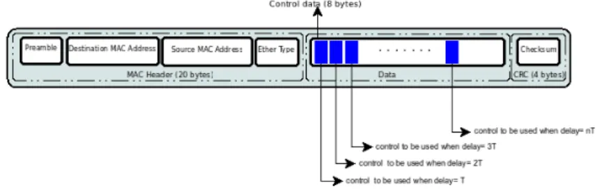
What follows is a brief description of the main concepts of PBC and of its functioning. The idea behind PBC is to send few packets with much more information instead of sending many packets with few data. The main concern of PBC is to find out how the ability to send more information into a single packet can be exploited to compensate for network delays. Figure 2 is a representation of a packet containing more controls and it describes the way they are used at different times for compensating time-varying delays. A way to compensate for the effects of delays is to compute a sequence of
Figure 2: Sending several control actions
control-predictions by means of the availability of a model of the plant. The aim of the model-based approach is to calculate a sequence of prediction in order to be able to control the plant for a fixed time horizon H. In this way the horizon H contains not only the control value to be applied to a specific instant but also the control values acting as a feedforward control signal between two transmission instants. We assume that the overall state of the plant is sensorized and a time-stamp is associated to each measurement. At each reception of a new measurement, the controller updates an internal model-based estimate of the current state of the plant. As soon as the model is set, the prediction sequence is computed by simulating the model
5they are upper limited when a successful transmission is considered, see [7] for a
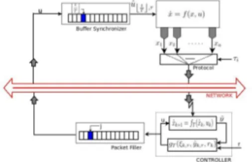
of the desired closed-loop system. The estimated dynamics is considered to be “stretched ” on the real time as if it were running concurrently with the plant. The computed control values sequences are coded and placed into the packet payload, and when the packet reaches the plant (i.e. with a certain delay), the onboard actuators select the most suitable control values based on the current time and time-stamping of the original measurements. Figure 3 shows the general control scheme. The main components are: the approximate time-discrete model of the plant (together with a stabilizing controller), the Packet Filler, and the Buffer Synchronizer. The Packet
Filler has the task to fill each control packet with a sequence of a predictive
values, while Buffer Syncronizer selects the most proper control action for compensating network delays on the basis of the time-stamp associated with each packet.
Figure 3: General control scheme for PBC.
How long a sequence of commands should be depends on the network parameters. In particular, the network protocol guarantees for periodic sending of the data; we define the sequence{τ = {τi} : τi > 0 ,∀i ∈ N} as
the sequence of times when it is possible to send. Regarding the sequence
τ , there exists a Maximum Allowable Time Interval (MATI) between two
consecutive sensors readings, which is defined as a positive number:
hm : τi+1− τi≤ hm,∀i ∈ N.
Moreover, the delays6 for each sending time τi are bounded and they are
defined as a sequence{δ = {δi} : ∃ δ : δi < δ ∀i ∈ N}. Since we must be sure
that the plant does never remain without control, the lenght of the horizon
H must be choosen so that:
(τi+1+ δi+1)− τi ≤ H , ∀i ∈ N.
The inequality implies that between two consecutive control packets there is some overlap among control value. This redundancy gets larger as the
6
The overall delay of the loop includes the delay of the network both on the sensor side either on the actuator side, and the computational time necessary to the controller for computing the control horizon.
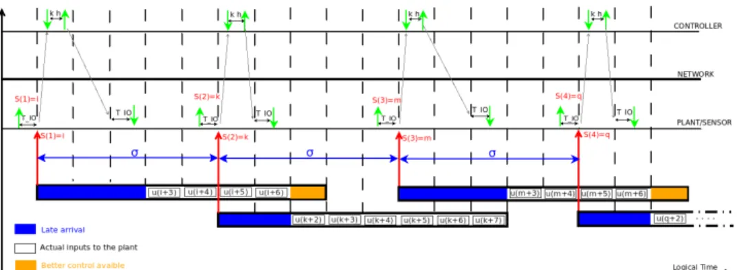
delay becomes longer. However, the plant will always use the more appro-priate control value contained in the last packet available. In figure 4 is
Figure 4: The times over network when PBC is applied
shown an example of how the packets are used for the PBC. The quantities
σ, kh, T IO, shown in figure 4, are respectively the “Maximum Allowable
Time Interval” (MATI) between two consecutive sensor measurements, the computational cost for calculating the control horizon and the time for in-put (outin-put) of the actuators (sensors). Furthermore, each dashed line is a different sampling istant, and we refer to two consecutive sampling times as a time-step. At each sampling time both the controller and the plant can send over the network. A description of the figure is the following: at the istant S(1), a time-stamped measurement of the state of the plant is sent over the network and it reaches the controller with a certain delay. By means of the time-stamp associated to the measure, the controller knows the time when the measure has been sent and it computes a control horizon reffered to a time-interval starting at S(1). The packet, in a bit more than two time-steps, reaches the plant, but the contained information is used as real control for the plant starting from three steps after. In this way, the first three control values are discarded (blue box in the figure) because of their late arrival. At the time S(2), a new information about the state of the plant is sent to the controller, which allows it to compute a new control horizon. The new control packet can be used by the plant after two time-steps from
S(2). Hence, the first two control values are discarded because of their late
arrival. It is worth noting that the last control value of the previous packet (orange box in the figure) is discarded because the value contained in the latest packet is better for that exact istant. However, if the network delay reaches its maximum value (as it happens, e.g., for the packet created from the istant S(2)), no control value is discarded.
As far as the stability of the system is concerned, several works have Stability considerations
derived very restrictive conditions for the stability. In particular, sufficient conditions for stability have been expressed in function of the maximum
al-lowable time interval between two consecutive sensor readings, and a bound on the tolerable delays and access frequency to the network has been de-rived. These conditions are usually evaluated considering a stabilizing static controller for state feedback. In our case, the controller is dynamic and the proof of the stability is more difficult to obtain. The key achievement of this work is to show the practicality and the advantages of the control approach by designing a simulator and doing some simulations on a case study.
As we said, the PBC is supposed to lead to a better usage of network The effects of the PBC approach
resources. In this regard, an analysis of the system effectiveness has been carried out, based on the network characteristics and the computing power of the controller that is needed to compute a control horizon. In particular, bounds for both the minimum computational speed—exploited for generat-ing predictions—and the maximum time incurrgenerat-ing between two consecutive sensor readings are derived. Such bounds depend on the network parame-ters (namely the cost of fixed overhead associated to each packet, the cost of a single control value, and the upper bound for the network delay). When such bounds are met, PBC exploits the available bandwidth more efficiently than classical control schemes.
It can be shown that the adoption of PBC leads to:
• a reduction of the number of network accesses within a given time
interval;
• the possibility to tolerate larger network delays.
In summary, PBC can increase the performance of the closed-loop system, while reducing the requirements in terms of bandwidth and real-time hard-ness for the communication link.
In order to verify the results of the use of PBC for controlling a dynami- Simulator
cal system, we wanted to perform some detailed simulations. So far, several simulation environments suitable to analyze portions of a networked control system have been developed, and the majority of them are tailored for par-ticular networked control paradigms. In this work, a simulation framework (named CoNCS), highly modular and able to provide support to a variety of existing approaches for control over network, has been developed at Centro Piaggio [2]. CoNCS has been used in order to create a custom simulator for the components of the PBC approach. In figure 5 the main blocks of the simulator are shown. In particular, on the Plant Side the block Smart
Sensors takes the measures, builds the packet and assigns the time-stamp to
each measurements. The block Smart Actuators selects the more appropri-ate control value for each time-step. On the Control Side the block Control
Logic at each sending time receives the packets from the sensors, initializes
the time-discrete model, starts the closed-loop for computing the sequence of control-predictions and undertakes the task of packet filler. The control
Figure 5: CoNCS simulator for the PBC approach.
packet contains the time-stamp referring to the sending time of the sen-sor measurements and the sequence of prediction. Furthermore, the block
Control Logic sends the control packets to the plant.
By means of the designed simulator, the control approach has been tested on a real scenario proposed by an important industrial automation provider: Siemens. The proposed benchmark—named ”Cutting a circle”—consists of controlling a machine tool during the cutting of a circle. For the evaluation of the controller, Siemens has defined some performance indexes:
• average radial relative error: deviation of the average radius of
the generated trajectory from the desired radius;
• maximum radial relative error: maximal absolute deviation from
the average radius calculated;
• area error: represents the average distance of the tool from its desired
position during the motion;
The two main parts of the testbed are the network and the plant. The plant is the machine tool (CNC), made by two axes, X and Z. The model of each one is obtained by a nonlinear finite element model (provided by Siemens) which is able to represent the dynamics of the machine in high detail. The axes dynamics are nonlinear and there is no coupling between the two of them, therefore the motion control is decoupled. The two axes move on orthogonal directions. For each axis, the controller receives as input the set-point position and the actual tool position as well as the setset-point velocity and the actual velocity. The generated control value is a setpoint force that will be given to the motor of each axis. The obtained structure is a cascade controller. It is composed by a proportional action (P) that regulates the tool position, i.e. the difference between the setpoint and the actual po-sition. The output of the proportional controller is used as a setpoint for the velocity controller, which in turn is a proportional integral (PI). The communicaton between the plant and the controller is done by PROFINET
[9], which provides for a real-time communication based on Ethernet tech-nology by guaranteeing deterministic data transfer. The main characteristic of PROFINET is the time-division multiplexing (TDM) scheme, which con-sists in subdivision of the time into a fixed-time communication cycle. Each cycle starts with a red phase, in which the channel is reserved for real-time communication, and the subsequent green phase (non-real-time communi-cation)7. At the moment, Siemens, for control applications, uses only the communication in the red phase (real-time comunication).
By means of CoNCS, several simulations of the described system have Simulations
been carried out. In figure 6, the simulation of a “Cutting a circle” task is reported. The circle has radius R = 0.05 m and the cutting velocity along circle is VB = 0.1 m/s. The figure shows the actual shape with amplified
error (red line), the desired shape (blue line) and the average amplified circle (dotted line). Furthermore, the simulator has allowed us to experimentally
−0.06 −0.04 −0.02 0 0.02 0.04 0.06 −0.06 −0.04 −0.02 0 0.02 0.04 0.06 0.08
geometric radial error, amplification=500
[m]
[m]
actual shape with exaggerated errors desired shape
average circle (exaggerated)
Figure 6: The cutting of a circle
evaluate the worsening in performance between the PBC and the conven-tional closed loop control (without network). In particular, the following index has been defined to evaluate the loss of performance caused by the introduction of the network:
I = bnet− bnominal bnominal
, (1)
where bnet is the benchmark value obtained by controlling the plant via the
network, and bnominal is the value of the same performance indicator with
no network. A comparison between the PBC and the classical control over
7
The transmission of any green frame must finish before the red interval starts. Hence it exists a yellow interval where frames are only transported if they fulfill this requirement. If this is not the case, they are buffered and sent out in the next green interval.
area error average radial rel. error maximum radial rel. error Conventional control 1.1634 1.2868 0.0858
PBC 0.0914 0.0914 0.1261
Table 1: Performance loss : I
network approach, based on the worsening index defined for the three bench-mark values, is reported in table 1; the values have been obtained considering a scenario where the maximum time interval between two consecutive sensor readings is σ = 20 time-steps = 2.5 ms and the control horizon is h = 24. The simulations show that the traditional methods for control over network have a maximum worsening in performance of approximately 128%, while the PBC approach is able to reduce it down to around 12%.
The approach presented here shows how it is possible, by means of a Conclusions
model-based approach, to exploit the large payload available on each packet by sending not only the value of the control law to be applied at one in-stant, but also a prediction of the control law; by this mean it is possible to compensate for network delays. After the presentation of the context and the formulation of the problem, we have described the general scheme of the control approach and we have shown how the packets can be used for compensating some network constraints. Finally, considering all the aspects described, it is possible to state that the main contribution of this work is that it has shown the practicality of the control approach applied to an industrial case study. The results about the applicability of the proposed method, obtained by means of simulations, are very promising.
Possible future developments of the proposed work are: Future works
• the design of a non-linear observer, well–suitable for packet-switching
network, for the estimate of the state of the plant;
• the proof of the stability of the system by taking the network
con-straints, the dynamic controller, and model uncertainty into account;
Bibliography
[1] A. Chaillet and A. Bicchi. Delay compensation in packet-switching net-worked controlled systems. In Decision and Control, 2008. CDC 2008.
47th IEEE Conference on, pages 3620–3625, 2008.
[2] S. Falasca, C. Belsito, A. Quagli, and A. Bicchi. A modular and lay-ered cosimulator for networked control systems. In Control Automation
(MED), 2010 18th Mediterranean Conference on, pages 273–279, 2010.
[3] L. Greco, A. Chaillet, and A. Bicchi. Exploiting packet size in uncertain nonlinear networked control systems. 2010.
[4] W.P.M.H. Heemels, A.R. Teel, N. van de Wouw, and D. Neˇsi´c. Net-worked control systems with communication constraints: Tradeoffs be-tween transmission intervals, delays and performance. Automatic
Con-trol, IEEE Transactions on, pages 1781–1796, 2010.
[5] J. Jasperneite, M. Schumacher, and K. Weber. Limits of increasing the performance of industrial ethernet protocols. In Emerging Technologies
and Factory Automation, 2007. ETFA. IEEE Conference on, pages 17–
24, 2007.
[6] L.A. Montestruque and P. Antsaklis. Stability of model-based networked control systems with time-varying transmission times. Automatic
Con-trol, IEEE Transactions on, pages 1562–1572, 2004.
[7] I.G. Polushin, P.X. Liu, and Chung-Horng Lung. On the model-based approach to nonlinear networked control systems. In American Control
Conference, 2007. ACC ’07, pages 281–286, 2007.
[8] Using State, Estimators J. K. Yook, D. M. Tilbury, and N. R. Soparkar. Trading computation for bandwidth: Reducing communication in dis-tributed control systems, 2000.
[9] Francesco Venturini. Analisi, sperimentazione e caratterizzazione