1 State of the art
1.1 Microsystems
The term microworld generally refers to microsystems with components in the range of 1 mm , with accuracy in the range of 10-3 mm , as shown in Figure 1.
Figure 1 Sizes and scales (source [1])
In the microdomain the gravity force becomes less important than other forces, so other handling strategies are required.
Nowadays, Microsystems, MEMS (Micro Electro Mechanical System), Nano are terms widespread used in research projects. As reported in [1], some significant fields in which these terms are involved are: the automotive industry (mainly accelerometers for airbag triggering); biomedical products (implantable micropumps for drug delivery, biosensors, equipment for minimal invasive surgery, etc). The same trend can obviously be observed in the microelectronic industry, in particular, the well known silicon based technology, strongly used in the microeletronic field, makes it possible today to produce cheap components integrating a lot of functionalities. These production techniques allow the 2D manufacturing to use several materials: glass, silicon, metals. Beside these applications from the semi-conductor industry, the conventional mechanical design also tries to reduce the size of the products and the emergence of micromechatronics develops new miniaturized devices with a lot of functionalities (sensing, actuation, guiding). The assembly of this reduced in size products led to downscaled production and assembly equipment, giving rise to several concepts like microfactory or new assembly strategies such as parallel assembly. Some equipment and especially the grippers are downscaled, but also new grippers, based on microworld related physics, are now commercially offered
The production of microsystems integrating many functionalities, many components made of different materials, requires flexible, modular accurate mechanisms, which can finely pick, orientate, move and release different types of objects in the right place. The assembling and packaging operations that achieve the microcomponents to be integrated into a hybrid microsystem is the very bottleneck of the manufacturing process. Actually, the main problem is the assembly and not the manufacturing of components. This is particularly true for very small components that require high positioning tolerances. High cost gripping principles for various applications concerning the handling and the assembling of microcomponents have been developed but they do not offer satisfying economical solutions yet (see paragraph 1.3). The main challenges characterizing microassembly are precise alignment of the component in several degrees of freedom, grasping and releasing of this delicate components and attaching them together.
In order to produce a miniaturized multifunctional system, some criteria have to be considered during the design: avoid or reduce assembly tasks, combine manufacturing and assembly operations, use self-assembly, use parallel assembly.
Currently, the term microfactory covers many developments, all aiming at producing miniaturised products with miniaturised equipment. Nowadays, several laboratories are involved in the development of microfactories trying to transform this concept from a technological achievement into an economically suitable product. The justifications for microfactories lie in the costs reduction of the production chain. Substantial cost reductions are made possible by downscaling the conventional assembly equipment or by using new assembly concepts. Microfactories mean infrastructure costs reduction, more flexible assembly (easy and flexible reconfigurations) and higher throughputs (faster production). An example of microfactory in which the production devices are downscaled is the one in Figure 2.
1.2 Forces acting in the microworld
When down scaled, volume forces (e.g. the gravity) tend to decrease faster than other kinds of forces such as the capillary force or the viscous force because they are proportional to the linear dimension. Although they still exist on macroscopic scale, these last forces are often neglected in macroscopic assembly. In a reduced system these so-called surface forces become predominant. According to the literature on microassembly, these forces are mainly the electrostatic forces, the Van Der Waals forces, the liquid bridge (also called capillary or surface tension) forces and the forces due to mechanical clamping. These forces can be reduced, overcome or on the contrary exploited as a gripping principle.
According to [1], a first simplified classification of the forces acting in microworld refers to four main categories:
2 gravity, with an infinite range;
2 electromagnetic force, with an infinite range; 2 weak force, with a range smaller than 10-18m; 2 strong force, with a range smaller than 10-15m;
These last two forces are outside the scope of this work due to their very short range (inside the nucleus). Electromagnetic forces represent the source of all intermolecular interactions and their influence can be combined to that of gravity in some phenomena as the rise of a liquid in small capillaries. The interactions between atoms, molecules and solids is characterized by chemical forces and covalent bonding, with a range over the order of an interatomic separation, and Coulomb force and ionic (or partially ionic) bond. Moreover, the interaction between microscopic bodies also depends on the Lifshitz- Van Der Waals forces whose interaction energy decreases as a function of the separation distance to the sixth or seventh power . A subtle investigation on Van Der Waals forces has been done by [1] and the conclusions are that these forces are negligible for separation distances above a few tens of nanometers and that are decreased by the roughness profile of the microcomponents and by the presence of water between two objects. Since the described conditions are the work conditions of the problem studied in the next paragraphs, Van Der Waals forces are neglected. Molecular interactions also play a role in adhesion, but, as their range is limited to interatomic separation, they would not be considered in what follows. Capillary forces play an important role in a lot of phenomena and applications: they provoke adhesion between microcomponents, cause reliability failure in MEMS applications and are of the utmost importance in microassembly.
1.3 Handling principles for microassembly
In the microassembly literature many works summarize the most important forces acting when dealing with microparts as: electrostatic forces, the Van Der Waals forces, the capillary forces, the gravity forces, the viscous forces. Although the way these forces are involved in microassembly is not completely understood yet, it is now well established by the scientific community that these forces are no longer negligible when manipulating and assembling parts lower than 1 mm in size.
A lot of different gripping principles exist in literature. In Figure 3 several gripping principles are showed:
Figure 3 Several gripping principles (source [1])
Figure 3a represents the friction gripping principle. Figure 4 shows a gripper that uses miniaturized tweezers. The fingers are actuated by a piezoelectric actuator.
Figure 4 Example of friction based gripper (source [1])
In Figure 5 there is a form closure gripper that is used to handle sensitive elements capturing it with flexible fingers. The principle is the one in Figure 3b .
Figure 5 Example of form closure gripper (source [3])
Figure 3c correspond to vacuum grippers that use pressure difference between the ambient atmosphere and the vacuum generated inside the gripper. Such tools (Figure 6) are widespread in industry.
Figure 6 Example of vacuum gripper (source [4])
Figure 3d represents magnetic grippers and particularly magnetic levitation whose use is limited to materials with high electrical conductivity and low temperature applications. The electrostatic grippers (Figure 3e) are used with conductive components. There are examples of these grippers that use the adhesion force to perform the gripping task and impose a detachment voltage for the release (Figure 7).
The “push-pull” gripper (Figure 3f) is an experimental solution and is based on adhesion forces that prevent the separation of the tip from the sphere (scheme in Figure 8).
Figure 8 Illustration of the push-pull manipulation (source [1])
In Figure 3g a capillary or surface tension gripper is represented. The surface tension forces can be used to get parts stuck to the gripper.
The one in Figure 3h is the principle of the cryogenic gripper represented in Figure 9. It is based on adhesive properties of ice to pick up microparts. The gripping strength of ice is up to 100 times stronger than that obtained with vacuum grippers, the surfaces of the objects are not damaged by handling process that is independent from materials properties.
Figure 9 Example of cryogenic gripper (source [6])
Aerodynamic grippers are represented in Figure 3i and in Figure 3j. The first type of grippers uses the Bernoulli effect to attract the object to the gripper, the second type use air cushion levitation.
Ultrasonic levitation is used by grippers in Figure 3k and Figure 3l. In the first figure a small component levitates in the pressure nodes of an acoustical standing wave between a
vibrating plane and a reflector (an application is shown in Figure 10). In the second figure the reflector of the standing wave is replaced by the levitated object.
Figure 10 Example of ultrasonic levitation (source [7])
In the laser gripper of Figure 3m, due to both the beam reflection and refraction, the component undergoes and axial force that always pushes it forward in the direction of the beam and a radial gradient force that traps it in the centre of the beam.
No prototype was built of the gripper based on Van Der Waals forces (Figure 3n) but it has been proposed in previous works. It uses Van Der Waals forces combined with surface tension or electrostatic effects.
Not all this principles can be used to handle components in micro domain (between 10 µm and 1 mm). The laser gripper, for example, is not useful because of its low developed force. The study of the cryogenic and the Bernoulli principles does not help to understand the underlying phenomena mentioned in the microassembly literature. The vacuum gripper is an interesting alternative to the downscaled mechanical gripper because it allows the handling of plane components with only an useful surface.
Nevertheless, the surface tension based gripping seems to be more promising, for example in terms of downscaling laws.
1.4 Capillary gripper
This work deals with the study of surface forces in microassembly and particularly the roles played by surface tension and capillary forces in the handling of small components. Capillary gripper is one of the most reliable gripping principle as demonstrated by the numerous papers in literature. The advantages of capillary grippers are the ability to grasp small components with only one upper free surface, components with an available little grasping area, any kind of component in terms of material and shape, fragile components because the meniscus between the gripper and the object act as a “bumper”. Moreover there is a favourable downscaling law (the force is proportional to the linear dimension while, for example, the vacuum grasping force is proportional to the area of the components and the gravity to the volume). Finally, the capillary gripper is compliant and exerts a self centring effect due to surface tension. The releasing phase in the capillary gripper is quite difficult even if numerous systems have been successfully tested.
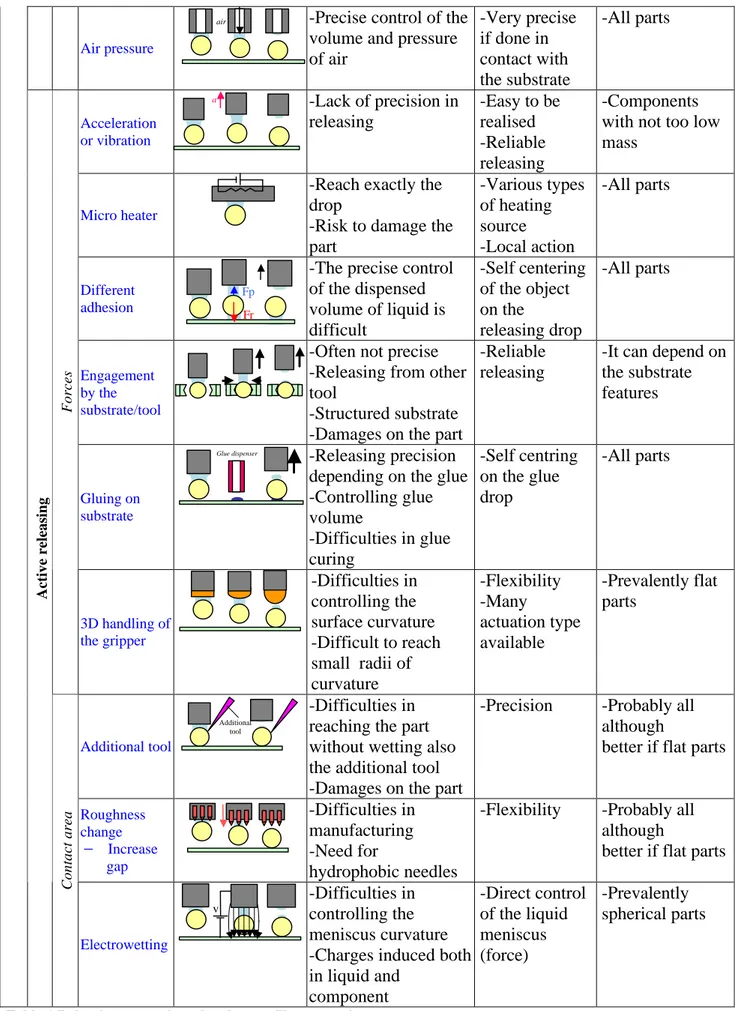
Table 1 (adapted from: Fantoni, Porta. Releasing strategies) shows releasing approaches
developed in literature for capillary grippers and the components that are possible to release. The releasing strategies are divisible into two separate groups:
o passive releasing strategies: exploit suitable gripper features or environment conditions
(in terms of shape, surface coatings and material) to make possible the reduction of the forces acting between gripper and microparts such as electrostatic, adhesion, Van Der Waals, in order to make simpler the releasing phase;
o active releasing strategies: make use of additional actions to allow the detachment of
the grasped object from the gripper. These additional actions can be (i) forces able to overcome the adhesive ones between gripper and object or (ii) means to reduce the contact area. With regards to additional forces, they can be supplied by external equipment or by suitable substrate (or substrate features) where the objects have to be released.
Possible Scheme Problems Advantages components Released
Gripper Hydrophobic coating -Manufacturing difficulties -Resistance of coating to many cycles -Flexibility -Parallel manufacturing by silicon technologies -Prevalently flat parts RELEASING PRINCIPLES Passive releasing Environment Atmosphere (heating the environment) -Energy consumption -Long cycle time -Scarce reliability -Easy to be realised -Probably all shapes
Hydrophillic areas Hydrophobic areas
Air pressure
-Precise control of the volume and pressure of air -Very precise if done in contact with the substrate -All parts Acceleration or vibration -Lack of precision in releasing -Easy to be realised -Reliable releasing -Components with not too low mass
Micro heater
-Reach exactly the drop
-Risk to damage the part -Various types of heating source -Local action -All parts Different adhesion
-The precise control of the dispensed volume of liquid is difficult -Self centering of the object on the releasing drop -All parts Engagement by the substrate/tool
-Often not precise -Releasing from other tool
-Structured substrate -Damages on the part
-Reliable releasing
-It can depend on the substrate features
Gluing on substrate
-Releasing precision depending on the glue -Controlling glue volume -Difficulties in glue curing -Self centring on the glue drop -All parts Forces 3D handling of the gripper -Difficulties in controlling the surface curvature -Difficult to reach small radii of curvature -Flexibility -Many actuation type available -Prevalently flat parts Additional tool -Difficulties in reaching the part without wetting also the additional tool -Damages on the part
-Precision -Probably all although
better if flat parts
Roughness change 2 Increase gap -Difficulties in manufacturing -Need for hydrophobic needles
-Flexibility -Probably all although
better if flat parts
Active releasing Contact area Electrowetting -Difficulties in controlling the meniscus curvature -Charges induced both in liquid and component -Direct control of the liquid meniscus (force) -Prevalently spherical parts
Table 1 Releasing strategies related to capillary grasping
v Additional tool Glue dispenser Fp Fr a air
![Figure 1 Sizes and scales (source [1])](https://thumb-eu.123doks.com/thumbv2/123dokorg/7336073.91366/1.892.204.693.347.536/figure-sizes-and-scales-source.webp)
![Figure 2 Example of microfactory (source [1])](https://thumb-eu.123doks.com/thumbv2/123dokorg/7336073.91366/2.892.338.556.880.1108/figure-example-of-microfactory-source.webp)
![Figure 5 Example of form closure gripper (source [3])](https://thumb-eu.123doks.com/thumbv2/123dokorg/7336073.91366/5.892.322.576.116.326/figure-example-form-closure-gripper-source.webp)
![Figure 9 Example of cryogenic gripper (source [6])](https://thumb-eu.123doks.com/thumbv2/123dokorg/7336073.91366/6.892.316.578.702.906/figure-example-cryogenic-gripper-source.webp)
![Figure 10 Example of ultrasonic levitation (source [7])](https://thumb-eu.123doks.com/thumbv2/123dokorg/7336073.91366/7.892.320.574.186.510/figure-example-of-ultrasonic-levitation-source.webp)