Ingegneria Energetica, Nucleare e del Controllo
Ambientale
Ciclo XXIX
Settore Concorsuale di afferenza: 09/C2 Settore Scientifico disciplinare: ING-IND/10
Dynamic modeling and seasonal performance
evaluation of air-to-water heat pump systems
Candidato:
Matteo Dongellini
Coordinatore Dottorato: Relatore:
Prof.Nicolò Cavina Prof. Gian Luca Morini
PhD Thesis – Bologna. 2017
Dynamic modeling and seasonal performance evaluation of air-to-water heat pump systems
Modellazione dinamica e valutazione delle prestazioni energetiche stagionali di sistemi basati su pompe di calore aria-acqua
Università di Bologna
Dottorato di ricerca in Ingegneria Energetica, Nucleare e del Controllo Ambientale (XXIX ciclo) E-mail: [email protected]
It is impossible for a self-acting machine, unaided by any external agency, to convey heat from one body to another at a higher temperature
--William Thomson (Lord Kelvin)
Here is the essence of this thesis: for the last three years I have been dealing with the second Law of Thermodynamics and I hope to go on for a while more
v
Acknowledgments
The research activity conducted during last three years would not have been possible without the support and the help received from many people: I am grateful to them all for their contribution.
First and foremost, I would express my gratitude to my supervisor, Prof. Gian Luca Morini, for his guidance, suggestions and valuable revision during these years. Prof. Morini supervised my work during my entire academic career: Bachelor Degree, Master Degree and PhD studies; he inspired in me and highlighted the passion for research and outlined the academic path that I am still walking: for these reasons, I am forever grateful.
This work was supported by the heat pump manufacturer Galletti Spa. I owe for the exchange of experience, the suggestion of practical ideas to solve unexpected problems and, last but not least, the provision of detailed technical and experimental data about heat pumps. None of the obtained results would have been possible without the support of Galletti Spa. In particular, the help of Dr. Alessandro Casolari, Dr. Antonio Loreto and Dr. Francesco Caselli needs to be acknowledged:
I am also very thankful to everyone in the Thermodynamics Laboratory of the University of Bologna, my current work place, for their help, technical support, friendship and for making every day here very enjoyable. A special mention goes to Dr. Stefania Falcioni, the first person to ask in the Lab when a doubt or a problem occurs.
I am deeply grateful with my colleagues Dr. Giacomo Puccetti and Dr. Claudia Naldi. We spent the major part of our academic studies together and they represent a milestone for my research activity, as well as precious friends.
Finally, my thoughts go to my family, for their encouragement, help, patience and support, to my friends and every person who spent a small part of its time with me during these last three years: there is a small share of all of them within this Thesis.
vii
Abstract
In this Thesis a series of numerical models for the evaluation of heat pump systems seasonal performance are presented. More in detail, the work has been addressed to the analysis of the behavior of reversible air-to-water heat pumps coupled to residential and non-residential buildings.
During last decades, several studies demonstrated that heat pumps are a suitable solution to achieve the targets imposed by the European Union in terms of energy saving and use of renewable sources since these devices are able to provide building space heating, space cooling and domestic hot water production with a single device using significant renewable energy contributions. Nevertheless, the exploitation of the full energy saving potential linked to the adoption of heat pumps in heating and cooling systems is a hard task for designers due to the influence on their energy performance of several factors, like the external climate variability, the heat pump modulation capacity, the system control strategy and the hydronic loop configuration. The aim of this Thesis is to study in detail all these aspects. It is important to stress that all the models presented in this work have been carried out with the cooperation of a heat pump manufacturer: this relationship has been important to obtain detailed data useful for the tuning of the developed models.
In the first part of this Thesis, a series of models which use a temperature class approach for the prediction of the seasonal performance of HVAC systems based on air source heat pumps are shown. An innovative methodology for the calculation of the seasonal performance of an air-to-water heat pump system operating in heating and cooling mode has been proposed as an extension of the procedure reported by the European Standard EN 14825. This methodology can be applied for the analysis of different kinds of air-to-water heat pumps, such as single-stage units (On-off HPs), multi-stage units (MSHPs) and inverter-driven units (IDHPs). By applying this method, the seasonal performance of the heat pump system is assessed as a function of the site in which the system is located, the building thermal loads, the size of the unit and the heat pump modulation capacity. If one considers heating operating mode, results point out that the optimal size of the heat pump strongly depends on its modulation capacity: for a fixed thermal load, a slight oversizing of multi-stage and variable-speed heat pumps leads to an increase of their seasonal efficiency, while the best seasonal
viii
number of on-off cycles to match the required load.
In the second part of this Thesis, dynamic simulations have been described with the aim to optimize the control systems of the heat pump and of the HVAC plant. A series of dynamic models, developed by means of TRNSYS, are presented in order to study the behavior of On-off HPs, MSHPs and IDHPs for building space heating and/or cooling. The main goal of the dynamic simulations presented in this work is to show the influence of the control logics linked to the heat pump and to the hydronic loop used in order to couple the heat pump to the emitters on the seasonal performance of the system and the indoor thermal comfort conditions guaranteed in a building. A particular focus is given to the implementation of innovative control strategies for the optimization of the heat pump energy consumption and to the modeling of the energy losses linked to on-off cycling.
It has been demonstrated that the adoption of optimized control logics can enhance the energy performance of the heat pump system because:
i. the hourly number of on-off cycles can be significally reduced (Sections
4.5.2 and 4.5.3);
ii. the heat pump can use on-off cycles only for a limited number of hours
during the winter (Section 3.7.1;
iii. the optimization of the hydronic loop configuration allows to stabilize
the temperature of the water supplied to the emitters, improving the indoor thermal comfort conditions.
ix
Sommario
Questa Tesi presenta una serie di modelli numerici sviluppati per la valutazione delle prestazioni stagionali di sistemi a pompa di calore. In particolare, il lavoro svolto durante questo periodo ha riguardato lo studio delle prestazioni energetiche di pompe di calore reversibili del tipo aria-acqua e accoppiate ad edifici residenziali e non residenziali.
Nel corso degli ultimi decenni, numerosi studi hanno dimostrato che le pompe di calore sono una soluzione promettente per raggiungere gli obiettivi imposti dall'Unione Europea in merito al risparmio energetico ed all'utilizzo di fonti energetiche rinnovabili, dal momento che questi sistemi sono in grado di soddisfare i fabbisogni energetici per il riscaldamento, il condizionamento e la produzione di acqua calda sanitaria per mezzo di un unico dispositivo e per giunta utilizzano quote significative di energia rinnovabile. Tuttavia, il pieno sfruttamento del potenziale risparmio energetico legato all'adozione di sistemi di
riscaldamento/condizionamento a pompa di calore è un compito di difficile
realizzazione da parte dei progettisti, in quanto diversi fattori come la variabilità delle condizioni climatiche esterne, la capacità delle pompe di calore di modulare la potenza termica/frigorifera erogata, la logica di controllo del sistema e la configurazione impiantistica utilizzata influiscono sulle prestazioni energetiche ottenibili. Lo scopo di questa Tesi è quello di studiare in dettaglio tutti questi aspetti. Si sottolinea come lo sviluppo di tutti modelli di simulazione presentati in questa Tesi sia stato effettuato in cooperazione con un produttore di pompe di calore. Tale collaborazione è stata determinante per ottenere dati tecnici dettagliati per la calibrazione dei modelli sviluppati.
Nella prima parte di questo lavoro, viene presentata una serie di modelli basati su un approccio di tipo "temperature class" per la previsione delle prestazioni stagionali di sistemi HVAC basati su una pompa di calore. Viene proposta una innovativa procedura di calcolo per la determinazione dell'efficienza stagionale di un impianto a pompa di calore ad aria operante in regime di riscaldamento e/o raffrescamento, costruita come una estensione della metodologia riportata dalla norma europea EN 14825. Tale procedura può essere estesa per lo studio di diverse tipologie di pompa di calore aria-acqua, quali pompe di calore monocompressore (On-off HPs), pompe di calore multi-compressore (MSHPs) e pompe di calore a velocità variabile (IDHPs). Impiegando la
x
calore dipende fortemente dalla capacità di modulazione della potenza
termica/frigorifera erogata dalla pompa di calore: una volta fissato il carico termico richiesto dall’edificio, un leggero sovradimensionamento della taglia di pompe di calore modulanti comporta un aumento dell’efficienza stagionale del sistema, mentre per quanto riguarda pompe di calore mono-compressore, la migliore performance stagionale si ottiene fissando una temperatura bivalente superiore alla temperatura di progetto. Inoltre, se si valutano le performance annuali di un sistema basato su una pompa di calore reversibile, i risultati ottenuti indicano che per ricavare la massima efficienza annuale sarebbe necessario progettare un edificio caratterizzato da carichi di progetto di riscaldamento e raffrescamento simili, al fine di ridurre l'utilizzo di sistemi di back-up o l'adozione di un numero significativo di cicli di on-off per adeguare la potenza termica/frigorifera erogata dalla pompa di calore al carico richiesto dall'edifiicio. Nella seconda parte di questa Tesi sono descritti modelli di simulazione dinamica costruiti con lo scopo di ottimizzare il sistema di regolazione di un impianto di riscaldamento. I modelli dinamici sono stati realizzati per mezzo di TRNSYS e permettono di valutare il comportamento in regime dinamico delle tipologie di pompe di calore precedentemente indicate (On-off HPs, MSHPs e IDHPs). Lo scopo principale dei modelli di simulazione dinamica presentati all'interno di questa tesi è quello di evidenziare l'influenza dei sistemi di regolazione della pompa di calore e del circuito idronico utilizzato per accoppiare il generatore di calore ai terminali di emissione sulle prestazioni stagionali dell'impianto e sulle condizioni di comfort garantite dall’impianto stesso.
Particolare attenzione è stata rivolta all'implementazione di strategie di
regolazione innovative ed alla modellazione delle perdite energetiche legate ai cicli di on-off della pompa di calore. E' stato dimostrato che l'adozione di logiche di controllo ottimizzate può migliorare le prestazioni energetiche degli impianti basati su una pompa di calore per differenti motivi:
i. il numero di cicli di on-off effettuati dalla pompa di calore può essere
xi ii. la pompa di calore è in grado di effettuare cicli di on-off per una parte
limitata della stagione;
iii. l'ottimizzazione della configurazione idraulica dell'impianto permette di
stabilizzare la temperatura di mandata dell'acqua, migliorando le condizioni di comfort termico che si realizzano all'interno dell'edificio.
xiii
Contents
ACKNOWLEDGMENTS ... V ABSTRACT ... VII SOMMARIO ... IX CONTENTS ... XIII LIST OF FIGURES ... XVII LIST OF TABLES ... XXIII NOMENCLATURE ... XXV ROMAN LETTERS ... XXV GREEK LETTERS ... XXVI SUBSCRIPTS/SUPERSCRIPTS ... XXVII ACRONYMS ... XXVIIIINTRODUCTION ... 1
1.1. OVERVIEW OF ENERGY USE IN THE EUROPEAN UNION ... 1
1.2. HEAT PUMPS MARKET SURVEY ... 4
1.2.1. EurObserv’ER statistic data ... 4
1.2.2. EHPA statistic data ... 9
1.3. MOTIVATION AND MAIN GOALS OF THE THESIS ... 11
1.4. THESIS OUTLINE ... 13
STATE OF THE ART ON HEAT PUMP APPLICATIONS AND THEIR CONTROL SYSTEMS ... 15
2.1. HEAT PUMP SYSTEMS: BASIC CONCEPTS ... 15
2.2. CLASSIFICATION OF ELECTRICAL HEAT PUMP ... 19
2.2.1. Surface Water Heat Pumps ... 19
2.2.2. Ground Water Heat Pumps ... 20
2.2.3. Ground Coupled Heat Pumps ... 21
2.2.1. Air Source Heat Pumps ... 22
2.2.2. Developments in air source heat pumps design ... 23
xiv
2.3. CONTROL SYSTEMS: BASIC CONCEPTS ... 27
2.3.1. On-off controllers ... 29
2.3.2. PID controllers... 30
2.3.3. A typical control algorithm of a heat pump system ... 32
2.4. INFLUENCE OF THE CONTROL SYSTEM ON THE ENERGY PERFORMANCE OF A HEAT PUMP SYSTEM ... 34
AIR-TO-WATER HEAT PUMPS MODELING AND SEASONAL PERFORMANCE EVALUATION THROUGH THE BIN-METHOD ... 37
3.1. HEAT PUMP PERFORMANCE MODELING ... 37
3.2. HEAT PUMP SEASONAL PERFORMANCE EVALUATION ACCORDING TO THE EUROPEAN STANDARD EN14825 ... 43
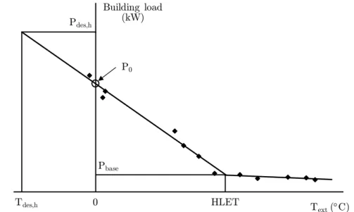
3.2.1. The Building Energy Signature method ... 46
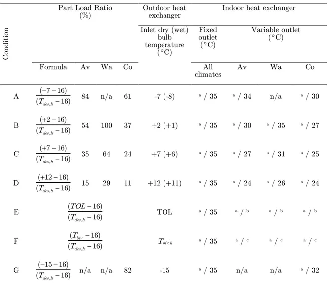
3.2.2. Assessment of heat pump performance according to EN 14825 .... 48
3.3. THE MATHEMATICAL MODEL FOR THE HEATING OPERATING MODE ... 54
3.3.1. Proposed methodology for heating operating mode ... 54
3.3.2. Bin profile and building energy signature ... 54
3.3.3. Development of heat pump characteristic curve ... 56
3.3.4. Calculation of the heat pump system seasonal efficiency ... 61
3.3.5. Seasonal performance factor evaluation in heating mode ... 65
3.4. THE MATHEMATICAL MODEL FOR THE COOLING OPERATING MODE ... 67
3.4.1. Evaluation of bin distribution, building energy demand and heat pump characteristic curves ... 67
3.4.2. Energy calculation in cooling operating mode ... 70
3.4.3. Seasonal performance factor evaluation in cooling mode ... 73
3.5. VALIDATION OF THE DEVELOPED MATHEMATICAL MODEL ... 74
3.6. ANNUAL PERFORMANCE FACTOR EVALUATION... 78
3.7. CASE STUDIES ... 80
3.7.1. Assessment of the influence of the heat pump modulation capacity on the seasonal performance of a heating system ... 81
3.7.2. Annual performances of reversible air-to-water heat pumps ... 92
DYNAMIC MODELING OF AIR-TO-WATER HEAT PUMP SYSTEMS ... 107
4.1. HEAT PUMP DYNAMIC SIMULATION MODELS IN LITERATURE ... 107
4.2. DYNAMIC SIMULATION OF AIR-TO-WATER HEAT PUMP SYSTEMS BY MEANS OF TRNSYS ... 114
4.2.1. The standard Types 917 and 941 ... 116
xv
4.2.3. The standard Type 534... 124
4.2.4. The plugin TRNBuild ... 130
4.3. DYNAMIC SIMULATION MODELS OF A HEATING SYSTEM BASED ON AIR-TO -WATER HEAT PUMPS ... 132
4.3.1. The considered hydraulic distribution loops ... 133
4.4. DYNAMIC MODELING OF AN AIR-TO-WATER HEAT PUMP... 136
4.4.1. TRNSYS model for a single-stage heat pump ... 137
4.4.2. TRNSYS model for a multi-stage heat pumps ... 139
4.4.3. TRNSYS model for an inverter-driven heat pump ... 143
4.4.4. TRNSYS model for the evaluation of heat pump cycling losses .. 147
4.4.5. TRNSYS model for the simulation of defrosting cycles ... 152
4.5. CASE STUDIES ... 155
4.5.1. Influence of the control system of a heating plant based on a heat pump on the Indoor Thermal Comfort ... 155
4.5.2. Optimization of the control strategy of a heat pump system coupled to a residential building ... 168
4.5.3. Assessment of the optimal thermal storage size of a heating system based on an air-to-water heat pump ... 179
CONCLUSIONS AND RECOMMENDATIONS FOR FUTURE WORK ... 191
5.1. CONCLUSIONS ... 191
5.2. RECOMMENDATIONS FOR FUTURE WORK ... 193
PUBLICATIONS ... 195
6.1. INTERNATIONAL JOURNALS... 195
6.2. NATIONAL JOURNALS ... 196
6.3. INTERNATIONAL AND NATIONAL CONFERENCES ... 196
xvii
List of figures
Figure 1.1. Annual gross energy consumption by energy source in Europe, from
1990 to 2015, (from [1]). ... 1
Figure 1.2. Annual final energy consumption by sector in Europe, from 1990 to 2015, (from [1]). ... 2
Figure 1.3. Fraction of energy sources in the residential sector in Europe in 2015, (from [1]). ... 3
Figure 1.4. Air-to-air heat pumps sold in the main European markets in 2015 (from [7]). ... 6
Figure 1.5. Hydronic heat pumps sold in the main European markets in 2015 (from [7]). ... 6
Figure 1.6. Heat pump sales in the European Union market (from [8]). ... 10
Figure 2.1. Logical scheme of a vapor-compression reversible heat pump: heating mode (a) and cooling mode (b). ... 16
Figure 2.2. Logical layout of a SWHP system (from [15]). ... 20
Figure 2.3. Logical layout of a GWHP system (from [15]). ... 20
Figure 2.4. Logical layout of a GCHP system (from [15]). ... 21
Figure 2.5. Typical layout of a horizontal heat exchanger configuration (a, from [24]) and a vertical heat exchanger configuration (b, from [28]). ... 22
Figure 2.6. Logical layout of a multi-stage heat pump characterized by N-stage compressor linked in parallel. ... 24
Figure 2.7. Logical layout of an inverter-driven heat pump. ... 25
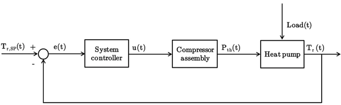
Figure 2.8. Logical scheme of a generic controlled system. ... 28
Figure 2.9. Logical scheme of a closed-loop control system. ... 28
Figure 2.10. Highlight on the hysteresis cycle of an on-off controller. ... 30
Figure 2.11. Logical scheme of pure proportional (P) controller. ... 31
Figure 2.12. Logical scheme of pure integral (I) controller. ... 31
xviii
Figure 2.14. Logical scheme of the control loop of a heat pump system. ... 33 Figure 3.1. Bin distribution of the Colder, Average and Warmer reference heating seasons provided by EN 14825 ([56]). ... 45 Figure 3.2. Bin distribution of the reference cooling season provided by EN 14825 ([56]). ... 45 Figure 3.3. Representation of a Building Energy Signature for the heating energy demand. ... 46 Figure 3.4. Example of BES and characteristic curve of a single-stage air-to-water heat pump in heating mode (Colder reference climate). ... 52 Figure 3.5. Example of BES and characteristic curve of a single-stage air-to-water heat pump in cooling mode (cooling reference climate). ... 53 Figure 3.6. Bin distribution during the heating season in Bologna (Italy) according to standard UNI/TS 11300-4 and the TRY of the location. ... 55 Figure 3.7. Winter BES and characteristic curve of a single-stage On-off HP. . 57 Figure 3.8. Winter BES and characteristic curves of a MSHP composed by 2 compressors. ... 58 Figure 3.9. Winter BES and characteristic curves of an IDHP evaluated for maximum, minimum and three intermediate frequencies. ... 59 Figure 3.10. Bin distribution for the reference cooling season and for Palermo (Italy) derived from the standard UNI 11300-4 and the TRY of the location. . 68 Figure 3.11. Characteristic curves of the selected On-off HP evaluated for heating (a) and cooling (b) mode, compared to performance data given by the manufacturer. ... 75 Figure 3.12. Characteristic curves of the selected MSHP evaluated for heating mode, compared to performance data given by the manufacturer (thermal capacity on the left, COP on the right). ... 76 Figure 3.13. Characteristic curves of the selected MSHP evaluated for cooling mode, compared to performance data given by the manufacturer (thermal capacity on the left, EER on the right). ... 76 Figure 3.14. Characteristic curves of the selected IDHP evaluated for heating mode, compared to performance data given by the manufacturer (thermal capacity on the left, COP on the right). ... 77
xix Figure 3.15. Characteristic curves of the selected IDHP evaluated for cooling mode, compared to performance data given by the manufacturer (thermal
capacity on the left, EER on the right). ... 77
Figure 3.16. Thermal capacity of the selected heat pumps as a function of the outdoor temperature (data obtained at full load for Tw,h=35C). ... 83
Figure 3.17. COP of the selected heat pumps as a function of the outdoor temperature (data obtained at full load for Tw,h=35C). ... 83
Figure 3.18. COP of the selected IDHP as a function of inverter frequency for different values of the outdoor temperature (data obtained for Tw,h=35C). .... 85
Figure 3.19. Bin trend, BES (case #7), heat pump thermal capacity at full load and at partial load: On-off HP (a), MSHP (b) and IDHP (c). ... 87
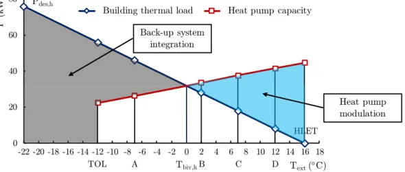
Figure 3.20. Building energy demand, thermal energy delivered by the heat pump and by the back-up system as a function of the outdoor temperature (case #7): On-off HP (a); MSHP (b); IDHP (c). ... 89
Figure 3.21. SCOPnet as a function of the bivalent temperature. ... 91
Figure 3.22. SCOPon as a function of the bivalent temperature. ... 92
Figure 3.23. Bin profiles of external temperature values during heating (a) and cooling season (b). ... 94
Figure 3.24. BES for heating and cooling season: Frankfurt (a), Istanbul (b) and Lisbon (c). ... 96
Figure 3.25. SCOPon as a function of the heating oversizing parameter OPh. .. 103
Figure 3.26. SEERon as a function of the cooling oversizing parameter OPc. ... 104
Figure 3.27. APF as a function of the overall oversizing parameter OPtot. ... 105
Figure 4.1. Extract of heating performance data required by Type 941. ... 117
Figure 4.2. Extract of cooling performance data required by Type 941. ... 117
Figure 4.3. Extract of heating performance data supplied for Type 996. ... 121
Figure 4.4. Extract of cooling performance data supplied for Type 996. ... 122
Figure 4.5. Extract of fan motor performance data supplied for Type 996. ... 122
Figure 4.6. Storage tank for domestic hot water production, (from [103]). ... 124
Figure 4.7. Logical layput of the thermal storage tank modelled by means of Type 534, (from [102]). ... 125
xx
Figure 4.8. TRNBuild main features. ... 131 Figure 4.9. Logic scheme of the developed dynamic models of the system building-HVAC plant. ... 133 Figure 4.10. Logic layout of a DHL heating system with the thermal storage placed in the supply line. ... 134 Figure 4.11. Logic layout of a DHL heating system with the thermal storage placed in the return line. ... 134 Figure 4.12. Logic layout of an IHL heating system characterized by constant flow rate in the secondary loop. ... 135 Figure 4.13. Logic layout of an IHL heating system characterized by variable flow rate in the secondary loop. ... 136 Figure 4.14. Hysteresis cycle of the on-off control system (heating mode). ... 138 Figure 4.15. Hysteresis cycle of the on-off control system (cooling mode). ... 138 Figure 4.16. Hysteresis cycle of the control system of MSHP composed by N compressors (heating mode). ... 140 Figure 4.17. High reactive and high stable behavior of a PID controller (from [51]). ... 144 Figure 4.18. Use of Type 581 to supply thermal capacity data of as a function of external temperature, return water temperature and inverter frequency. ... 145
Figure 4.19. Use of Type 581 to supply COP data of as a function of external
temperature, return water temperature and inverter frequency. ... 145 Figure 4.20. TRNSYS Type 23 (PID controller) characteristics. ... 146 Figure 4.21. Layout of the dynamic model of an inverter-driven heat pump and its control system. ... 147 Figure 4.22. Schematic representation of a TEV (from [106]). ... 150 Figure 4.23. Schematic representation of an EEV (from [106]). ... 151 Figure 4.24. Typical defrosting cycle for an air-source heat pump based on the inversion of the refrigerant thermodynamic cycle. ... 154 Figure 4.25. Position of Istituto G. Marconi within Castelfranco Emilia. ... 156 Figure 4.26. Streetview of the South side of Istituto G. Marconi. ... 156
xxi Figure 4.27. 3D model of Istituto G. Marconi developed by means of Google Sketch-Up. ... 159 Figure 4.28. Layout, orientation and zoning of the first floor of Istituto G. Marconi. ... 160 Figure 4.29. Bin distribution of Top for the selected classrooms of Istituto G.
Marconi. ... 161 Figure 4.30. Dynamic model of Istituto G. Marconi after the heating system refurbishment. ... 162 Figure 4.31. Behavior of the control system of the multi-stage heat pump selected for the heating system refurbishment. ... 164 Figure 4.32. Heat pump thermal capacity and inlet/outlet water temperatures during a typical day of the heating season. ... 165
Figure 4.33. Comparison between the bin distributions of Top before and after the
heating system refurbishment. ... 166 Figure 4.34. Layout of the residential building and indication of simulated thermal zones. ... 168 Figure 4.35. Hourly building thermal load with the highlighting of the BES (a), building energy demand and bin distribution as a function of Text (b). ... 170
Figure 4.36. On-off heat pump thermal capacity and COP as a function of Text
and Tw,out. ... 171
Figure 4.37. MSHP thermal capacity (a) and COP (b) as a function of Text, Tw,out
and number of compressors switched on... 171
Figure 4.38. IDHP thermal capacity (a) and COP (b) as a function of Text, Tw,out
and inverter frequency. ... 171 Figure 4.39. BES, thermal capacity at full load and at partial load of the considered heat pumps as a function of Text. ... 172
Figure 4.40. Behavior of the control system of single-stage (a) and multi-stage (b) heat pumps. ... 173 Figure 4.41. Daily on-off cycles of the simulated systems as a function of the daily average external air temperature. ... 175 Figure 4.42. Optimized control logic for the multi-stage unit (MSHPopt). ... 176
xxii
Figure 4.44. Plan of the building (left) and 3D model developed by means of Google SketchUp (right). ... 180 Figure 4.45. Layout of the heating system configuration A0. ... 183 Figure 4.46. Annual on-off cycles as a function of volume and position of the thermal storage (heating system A)... 184 Figure 4.47. Annual on-off cycles as a function of the thermal storage volume (heating system configurations C and D). ... 185 Figure 4.48. Hourly on-off cycles performed by the heat pump as a function of the ratio between water volume and the unit rated capacity. ... 186
Figure 4.49. SCOP values for the heating system A2 as a function of the tank
volume. ... 187 Figure 4.50. SCOP values for the considered heating systems as a function of the tank volume. ... 188
xxiii
List of Tables
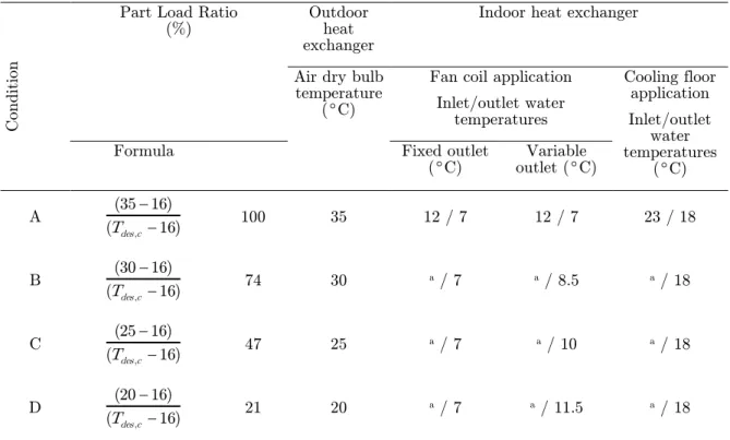
Table 1.1. Heat pumps stock in Europe in 2015 (from [7]). ... 7 Table 3.1. Test conditions for air-to-water heat pumps in heating mode according to EN 14511-2 [73] (Low temperatures). ... 42 Table 3.2. Test conditions for air-to-water heat pumps in heating mode according to EN 14511-2 [73] (High temperatures). ... 43 Table 3.3. Test conditions for air-to-water heat pumps in cooling mode according to EN 14511-2 [73] (Low temperatures). ... 43 Table 3.4. Part load conditions of AWHPs in low temperature applications for the reference heating seasons. ... 50 Table 3.5. Part load conditions of AWHPs for the reference cooling season. .... 51 Table 3.6. Polynomial coefficients of the On-off HP characteristic curves obtained by means of the developed model. ... 74 Table 3.7. Selected heat pumps rated performance (7C dry bulb, 6C wet bulb for outdoor air temperature; 40-45C inlet/outlet water temperature) and their main technical characteristics. ... 81 Table 3.8. Performance of the selected MSHP at full load (2/2 data) and at partial load (1/2 data) for a fixed value of the hot water temperature (Tw,h=35C). ... 84
Table 3.9. Building design loads and values of Tbiv,h and Tcyc,h obtained through
simulations. ... 86 Table 3.10. Values of seasonal performance of the whole heat pump system for case #7. ... 90 Table 3.11. Geometrical and thermal characteristics of the office building. ... 93 Table 3.12. Main climatic data of the selected locations. ... 93 Table 3.13. Thermal/cooling capacity and COP/EER at full load of the simulated On-off HPs. ... 98
Table 3.14. Thermal/cooling capacity and COP/EER at full load of the simulated
MSHPs. ... 99 Table 3.15. Thermal/cooling capacity and COP/EER at full load of the simulated IDHPs. ... 100
xxiv
Table 3.16. Heating and cooling capacity at full load at the design temperature of the considered heat pumps and oversizing (or downsizing) with respect to building design loads. ... 101 Table 3.17. Seasonal and annual performance factors obtained for the considered heat pump units. ... 102 Table 4.1. Typical values of on-off cycles penalization parameters with respect to the expansion valve typology. ... 152 Table 4.2. Geometrical data of Istituto G. Marconi. ... 157 Table 4.3. Thermophysical data of the school envelope components. ... 158 Table 4.4. Ooccupancy schedule of the building and heating system operating schedule. ... 159 Table 4.5. PHP,h and COP of the heat pump selected for the heating system
refurbishment of Istituto G. Marconi as a function of Text and the number of
working compressors. ... 163 Table 4.6. Bin distribution of hourly PMV values before and after heating system refurbishment. ... 167 Table 4.7. Geometrical and thermo-physical data of the residential building. . 169 Table 4.8. Cycling losses parameters for the simulated heat pumps. ... 174 Table 4.9. Seasonal performance of the simulated systems as a function of the HP typology. ... 177 Table 4.10. U-values of the building envelope components. ... 180 Table 4.11. Description of the heating systems developed within TRNSYS. ... 181 Table 4.12. PHP,hand COP of the selected heat pumps as a function of Text and of
the working compressors (data evaluated for Tw,in/Tw,out = 40/45C). ... 182
Table 4.13. Thermal storage volumes considered in the simulations. ... 183 Table 4.14. Optimal values of the water volume - rated thermal capacity ratio for the considered configurations. ... 189
xxv
Nomenclature
Roman letters
A Area
APF Annual Performance Factor
Cc Degradation coefficient for on-off cycling penalization
CF Corrective Factor during heat pump start-up
COP Coefficient Of Performance
COPC Carnot Coefficient Of Performance
cp Specific heat capacity at constant pressure
CR Capacity Ratio
CS Cooling control Signal
d Disturb variable of a generic control system
DB Dead Band
DD Degree Days
DT Temperature Difference
e Error signal of a generic control system
EER Energy Efficiency Ratio
EERC Carnot Energy Efficiency Ratio
EP Energy Performance indicator
fcorr Corrective factor for on-off cycling penalization (bin method)
fp Primary energy conversion coefficient for electrical energy
H Number of hours
HS Heating control Signal
i i-th bin or hour
j j-th inverter frequency
K Number of tank nodes
k Thermal conductivity
Kd Derivative gain of a PID controller
Ki Integral gain of a PID controller
Kp Proportional gain of a PID controller
L Distance
xxvi
m Mass flow rate
n Number of active compressors of a multi-stage heat pump
N Compressor number of a multi-stage heat pump
OP Oversizing Parameter
p Pressure
P Power
PLF Part Load Factor
PMV Predicted Mean Vote
Pth Thermal power delivered by the heat pump
Q Thermal power
Qh Thermal power rejected to the hot heat source
Ql Thermal power absorbed from the cold heat source
RH Relative Humidity
S Slope of the building energy signature
SCOP Seasonal Coefficient Of Performance
SEER Seasonal Energy Efficiency Ratio
T Temperature
t Time
Td Characteristic derivative time of a PID controller
Th Hot heat source temperature
Ti Characteristic integral time of a PID controller
Tl Cold heat source temperature
Top Operative Temperature
u Input signal of a generic control system
U Thermal transmittance
uDB Upper Dead Band
UI Unbalance Indicator
V Volume
Wel Compressor electrical work
X Output variable of a generic control system
Greek letters
Timestep duration
Ф Frequency
xxvii η Efficiency
Subscripts/superscripts
abs Absorbed air Air aux Auxiliary avg Average b Buildingbase Base value
bin Bin
biv Bivalent
bottom Bottom part of the tank
BU Back-up c Cooling ck Crankcase Heater cnd Conduction compr Compressor cond Condenser cyc Cycling DC Defrosting Cycle des Design dspr Desuperheater
edge Edge part of the tank
eff Effective el Electric env Environment eva Evaporator ext External FC Fan-coil FL Full Load
flow Flow of a fluid stream
h Heating
in Inlet
lim Limit
xxviii
max Maximum
min Minimum
mix Mixing
net Of the heat pump
off Off
on Of the heat pump and the back-up system
opt Optimal out Outlet pen Penalization r Return ref Reference sb Stand-by SP Set-Point SU Start-up
tank Storage tank
to Thermostat-off
top Top part of the tank
tot Total
w Water
Acronyms
AAHP Air-to-Air Heat Pump
AHP Absorption Heat Pump
ASHP Air Source Heat Pump
Av Average reference climate
AWHP Air-to-Water Heat Pump
BES Building Energy Signature
BHE Borehole Heat Exchanger
CLET Cooling Heating Limit Temperature
Co Colder reference climate
DHL Direct Hydraulic Loop
DHW Domestic Hot Water
EEV Electronic Expansion Valve
EHP Electric Heat Pump
xxix
EU European Union
GCHP Ground Coupled Heat Pump
GHG Green House Gas
GHP Gas-engine Heat Pump
GSHP Ground Source Heat Pump
GWHP Ground Water Heat Pump
HiL Hardware-in-the-Loop
HLET Heating Limit External Temperature
HP Heat Pump
HVAC Heating, Ventilating and Air Conditioning
IDHP Inverter-Driven Heat Pump
IDL Indirect Hydraulic Loop
MSHP Multi-Stage Heat Pump
NZEB Nearly Zero Energy Building
On-off HP Single-stage On-off Heat Pump
PID Proportional-Integrative-Derivative
RES Renewable Energy Source
Sep Hydraulic Separator
SPF Seasonal Performance Factor
SWHP Surface Water Heat Pump
TEV Thermostatic Expansion Valve
TOL Temperature Outlet Limit
TS Thermal Storage
TRY Test Reference Year
1
Chapter 1
1. NUMERO
Introduction
1.1.
Overview of energy use in the European Union
The economic growth achieved during the previous century has been based on a progressive increase of energy consumptions. During the last decade, this trend undergoned a change, with an unexpected decrease of the energy demand due to the financial crisis occurred in 2009 and, of course, the increase of energy efficiency. In Figure 1.1, the European annual use of gross energy from 1990 to 2015, according to Eurostat data [1], is reported, subdivided for energy source.
Figure 1.1. Annual gross energy consumption by energy source in Europe, from 1990 to 2015, (from [1]).
As pointed out by Figure 1.1, the contribution of fossil fuel energy sources (i.e. carbon, oil and gas) on the European gross energy consumption is predominant. Nevertheless a slow but continous decreasing trend, the share of fossil-fuel-based energy sources accounted in 2015 for about the 73% of the overall gross energy consumption. The exploitation of fossil fuels causes a series of environmental problems as the emission of carbon dioxide and other pollution; for this reason, the European Union (EU) is struggling to decrease the overall energy
0 400 800 1200 1600 2000 1990 1992 1994 1996 1998 2000 2002 2004 2006 2008 2010 2012 2014 G ros s en er gy c on su m p ti on ( M toe)
Renewable energies Nuclear source Gas Oil products Solid fuels
2
consumption by means of the improvement of energy efficiency and to spread the use of Renewable Energy Sources (RES).
The negative environmental effects of fossil fuel combustion has been an increasing concern for the European Union during the last decades. Several targets have been defined in order to achieve a significant reduction of Greenhouse Gas (GHG) emissions, both on supply and demand side, with the aim to significantly increase the share of Renewable Energy Sources (RES) among the global energy consumptions. In addition to the European targets imposed for 2020, known as the 20-20-20 targets and reported by the Directive 2209/29/EC [2], the EU has established more restrictive targets to be achieved by 2030 [3], namely: the reduction of 40% of GHG emissions, compared to 1990 level, a RES share of 27% in the final energy consumption and the increase of energy efficiency at least of 27%.
Figure 1.2 illustrates the European final energy demand by sector from 1990 to 2015 (data are extracted from Ref. [1]). It is evident from Figure 1.2 that the share of energy use in the residential and service sectors is relevant: the mentioned sectors accounted for about the 39% of the overall European final energy consumption in 2015, corresponding to about 420 MToe. The energy consumption of the residential and the service sectors are mainly due to building operation energy demand.
Figure 1.2. Annual final energy consumption by sector in Europe, from 1990 to 2015, (from [1]).
The fractions of energy sources used in residential sector during 2015 are better highlighted by Figure 1.3, from which it is evident that almost the half of final
0 300 600 900 1200 1990 1992 1994 1996 1998 2000 2002 2004 2006 2008 2010 2012 2014 F in al e n er gy c on su m p ti on ( M toe ) Agriculture/Forestry Services Residential Transport Industry
3 energy consumption linked to residential building operation is provided by fossil fuels (i.e. petroleum products and natural gas).
As a consequence, EU made a strong effort to achieve a significant decrease of both new and refurbished building energy consumptions through a reduction of the use of fossil fuels, the enhancement of buildings energy efficiency and a wider diffusion of RES systems. During last ten years, a series of European Directives, aimed to promote the use of renewable sources and improve the energy efficiency in buildings, have been published. In particular, the Energy Performance of Building Directive, known as the EPBD Directive [4], promotes in the EU Member States the transition to Nearly Zero Energy Buildings (NZEB, namely buildings with very low energy needs) within 2020 and defines the minimum energy performance requirements for the building envelope and the heating, cooling and air-conditioning (HVAC) systems for new and old buildings.
Figure 1.3. Fraction of energy sources in the residential sector in Europe in 2015, (from [1]).
In 2012, another important Directive was adopted: the Energy Efficiency Directive (EED) [5]. According to the EED, the Member States have to indicate several targets of primary energy savings for 2020: more in detail, concerning buildings, the EED imposes that European countries must renovate a share of 3% of buildings owned or occupied by the Public Administration, each year.
Furthermore, in 2009 the Directive 2009/28/EC ([6]) has officially recognized the Heat Pumps (HPs) as systems which use renewable energy sources. For this reason, heat pumps are a suitable solution for the replacement of boilers in new and retrofitted buildings and this kind of systems can contribute to achieve the targets reported by the mentioned European Directives, since aero-thermal,
12,7% 35,6% 15,7% 3,3% 25,0% 7,8% Total petroleum products
Gas
Renewable energy Solid fuels Electrical energy Derived heat
4
geothermal and hydrothermal sources have been recognized as renewable energy sources
1.2.
Heat pumps market survey
Heat pumps are typically grouped into three main categories: ground source heat pumps (GSHPs), which use as external thermal reservoir the ground, hydrothermal heat pumps, whose external heat source is water (from ground, rivers or lakes), and air source heat pumps (ASHPs), which extract thermal energy from air (outdoor, exhaust or indoor air). In order to carry out a survey on the last developments of the heat pump market within the European Union, we have merged the ground source and hydrothermal heat pumps statistics for sake of convenience.
Climate strongly influences the use of heat pump systems. In the coldest part of Europe, heat pumps are basically employed for heating purposes. In hotter areas as the Western and Southern Europe regions (Italy, Spain and France), the market of reversible heat pumps is bigger, because the cooling demand increases significantly and in some countries becomes predominant.
1.2.1. EurObserv’ ER statistic data
If one considers the European market as a whole, 2015 was a positive year for the heat pump sector. According to EurObserv’ ER 2015 data, reported in [7], over 2 600 000 heat pump units were sold in 2015, taking all above-mentioned technologies into account, corresponding to 20% growth with respect to 2014. Within the European market, up to 88% of sales are related to air-to-air heat pumps (AAHPs), corresponding to about 2 300 000 units. Low investment costs and easy installation make this kind of systems more suitable for the renovation market sector and constitute the basis for their very significant market share. Nowadays most of the air-to-air units sold in Europe are reversible and cooling needs have a strong influence on their high demand: market sales were in fact boosted by high summer temperatures in the Southern countries. Among ASHPs sales, the impact of units which extract heat from exhaust air is negligible, since only 28 000 units were sold in Europe in 2015.
The heat pump market for hydronic systems (i.e. GSHPs and air-to-water heat pumps, AWHPs) has sharply increased, too. This market gained 10% in
5 2015, with almost 300 000 units sold in the whole Europe. The air-to-water heat pump market segment is characterized by the biggest share, with about 220 000 units sold in 2015, corresponding to 14.5% growth on the year before. The ground-source heat pump market appears to be stable after many years of declining sales: about 82 500 units were sold in 2015, compared to about 82 750 units sold in 2014 (-0.3%).
In Figure 1.4 and Figure 1.5 the distribution of the air-to-air and hydronic heat pump units sold in 2015 is spreaded among the main European countries, respectively. As pointed out by Figure 1.4, the annual sales of air-to-air units in the larger Southern European markets (i.e. Italy, Spain and France) are strongly higher than other European countries. However, data from these markets are not directly comparable to the others, since the sales of heat pumps characterized by cooling as principal function are included. On the contrary, in Northern European countries they is a high demand of heat pumps in heating operating mode, since cooling needs are negligible.
It is evident from Figure 1.5 that in Europe the sales of hydronic heat pump systems are about one order of magnitude lower with respect to air-to-air units sales. Within this category, the air-to-water heat pumps (AWHPs) represent around 73% of the market in 2015, against the 27% share of ground source heat pumps [7]. This is due to the higher complexity and the higher installation costs of the GSHP systems, mainly associated to the boreholes drilling expenses, which delay the economic savings of ground source heat pumps. Improved and innovative methods for the boreholes drilling are needed to reduce the installation costs and the impact on the surroundings of this kind of systems, in order to achieve a higher ground source heat pumps penetration in the market.
Among the main European markets for hydronic systems, one can note important differences. The major number of ground source heat pumps are located in Northern and Central Europe; the highest percentage of GSHPs sales (with respect to the total of sold hydronic systems) can be found in Sweden and Finland, in which about 77% of this market sector is related to ground source units. Furthermore, the countries located in the European Central region present a market share of GSHPs higher than the average: in Denmark, Germany and Austria this sector covers a percentage of 37%, 34% and 30% on the total of hydronic systems sales, respectively. Finally, GSHPs are also used in Southern Europe, but at a very small scale: the sales of this kind of systems are completely negligible if compared to air-to-air systems market (as highlighted by Figure 1.4 and Figure 1.5).
6
Figure 1.4. Air-to-air heat pumps sold in the main European markets in 2015 (from [7]).
Figure 1.5. Hydronic heat pumps sold in the main European markets in 2015 (from [7]).
From another point of view, it is hard to estimate the total number of the installed heat pumps from the data supplied by industry associations and by European Member States. According to [7], the heat pumps installed in the European Union approaches 29.5 million units at the end of 2015. Table 1.1 reports the number of operating heat pumps for each Member State, subdivided among air source and ground source systems.
Concerning the installed thermal capacity and renewable energy outputs of this kind of systems, EurObserv’ ER indicates a total capacity of 206.7 GW installed at the end of 2015, including 188.2 GW of air source heat pumps thermal capacity and 44.2 GW of thermal capacity linked to hydronic systems (25.7 GW of air-to water units; 18.5 GW of geothermal and hydrothermal units).
0 200 400 600 800 1000 IT ES FR PO SE DE FI NL BE DK UK AT M ar k et of AAHP s (k u n it s) 0 20 40 60 80 FR DE SE IT UK AT FI ES NL BE DK PO M ar k et of h y d ron ic HP s (k u n it s) Hydronic HPs AWHPs GSHPs
7 Table 1.1. Heat pumps stock in Europe in 2015 (from [7]).
Country Air source heat pumps
(Air-to-air, air-to-water, exhaust air)
Ground source heat pumps (Ground coupled, ground
water, surface water)
Total (k-units) Italy 18 430 16 18 446 France 4 638 149 4 787 Spain 1 497 1 1 498 Sweden 988 498 1 486 Germany 567 330 897 Finland 578 95 673 Denmark 245 56 301 Netherlands 248 47 295 Poland 255 0.8 256 Austria 67 96 163 United Kingdom 115 27 142 Belgium 84 8 92 Others 431 81 512 European total (k-units) 28 143 1 405 29 548
Heat pump technology is a widespread solution in the new buildings sector because it is particularly suitable for well-insulated constructions. Heating and cooling systems for these kinds of buildings are characterized by low temperature terminal units and are characterized by low specific energy consumptions. The mentioned characteristics can be coupled very well with the features of the heat pumps, which are the main candidate for the heating and cooling supply in low energy buildings (i.e. NZEB). On the other hand, until now a challenge for the heat pump industry is to make inroads into the renovation building market (primarily for the replacing of gas-fired boilers), which dominates HVAC system sales.
This trend is nowadays emerging in mature markets like France and North Europe. It means that these innovative devices can meet the needs of renovation operations and can also gain market shares in countries where heating systems based on heat pumps are less widespread. Finally, another reason for this positive
8
trend in the renovation market comes from the new expectations of building dwellers for comfort, especially being able to cool their homes during summer.
According to this trend, new products that are dedicated to the renovation market have been recently launched on the heat pump market. One of the widespread solutions includes a hybrid system composed by a condensing boiler and a heat pump within the same device. This system offers the advantage of enabling old housing renovation without the replacement of their original high-temperature radiators. The use of an auxiliary system (i.e. the boiler) implies that the heat pump does not need to be oversized and that the system efficiency is increased when the external temperature is very low. The energy manager of the system calculates the most efficient operating mode (boiler only, hybrid or heat pump only), according to the values of internal and external parameters, such as gas and electricity prices, external temperature and thermal capacity required. It is worth noting that hybrid heat pump systems were originally developed by heating market generalists that are not only boiler but also heat pump experts. Nowadays, this market is also targeted by the most important air-conditioning players.
Recently, modulation heat pumps have been launched and this product segment represents the most promising technology. These units use an inverter to continuously modulate the compressor rotating speed to match the requested thermal load. Electricity consumption can be optimized, maximum energy performance can be obtained and noise can be minimized by managing the compressor frequency. While conventional single-stage heat pumps operate at full load until the set-point temperature is reached and then are switched off, inverter-driven units operate continuously to provide a more efficient control of the system. These variable-speed compressor heat pumps have been successfully used since many years in air-conditioning technology and they were initially engineered by the major Asian players.
The proliferation of new technological solutions offered by heat pump manufacturers is an indication of the growth potential of this market. Therefore, the promulgation of a series of European Directives ([4]-[6]), aimed to improve the energy efficiency of buildings and HVAC systems by means of a series of targets imposed to Member States, leads to a continuous increase of industry financial profit.
9
1.2.2. EHPA statistic data
An interesting source of data for the analysis of the heat pump market is the European Heat Pump Association (EHPA); EHPA publishes each year the European Heat Pump Market and Statistics Report, in which it incorporates only the fraction linked to the heating mode of the reversible air-to-air heat pump sales in the countries where they are installed. This choice is justified by its objective to monitor the market of heat pump systems primarily used for heating and for this reason it distinguishes them from the market of systems mainly used for cooling. More in detail, EHPA considers that reversible air-to-air heat pumps are principally used for heating in countries characterized by cold climates (North and East Europe). Moreover, the Association avoids to incorporate air-to-air heat pump sales within the sales statistics of countries located in temperate zones (i.e. Middle Europe). Finally, with regard to countries located in the Southern part of Europe and characterized by hot climates, EHPA takes into account only a small fraction of air-to-air heat pump sales (actually about 10%), which represents the percentage of heat pumps used for heating needs only.
In Figure 1.6 the European heat pump market of the last ten years is represented, according to EHPA statistic data [8] and definitions (i.e. only the sales of reversible air-to-air heat pump mainly used for heating are considered). As pointed out by Figure 1.6, the heat pump market has been characterized by different trends within the last ten years. Between 2005 and 2008 a significant increasing tendency of sales can be observed, while from 2009 to 2012 the market dropped down due to the financial crisis occurred in 2009 and, although it has partially recovered during 2010 and 2011, the heat pump sales dropped again in 2012 to values below the sales of four years before. This last drop can be explained by the crisis of the construction sector occurred in some countries and by the increase of the electricity prices, among others. Since 2013, the tendency reversed again: heat pump sales increased year by year and in 2015 they reached the record year sales of about 880 000 units.
Figure 1.6 also splits heat pump sales within three main categories: air-to-air units (AAHPs), air-to-water units (AWHPs) and ground source units (GSHPs, which include heat pumps that extract heat from ground or water). The reported data highlight that air source units have been the most widespread solution in the heat pump market: only a share that ranges between 10% and 20% of yearly heat pump sales covered by ground source devices. Moreover, compared with a
10
slightly decrease of ground source heat pumps market during last years, air-to-water units sales have significantly increased.
Figure 1.6. Heat pump sales in the European Union market (from [8]).
In addition, the EHPA Statistic Report [8] highlights how the heat pump European market continues to be characterized by three main trends:
air is the most employed energy source for heat pumps;
domestic hot water (DHW) heat pump systems are the most promising market segment within Europe. Domestic hot water systems combine a heat pump and a hot water thermal storage and they may be sold as stand-alone units, with the heat pump and the tank combined in the same device, or as separate systems. In 2015 about 118 000 domestic hot water heat pumps were sold in Europe, corresponding to an increase of about 4% over 2014 sales and as much as 84% over 2012 sales;
large heat pumps for industrial, tertiary and district heating applications are widespread solutions. They often employ geothermal or hydrothermal energy sources, but also for this kind of systems air is an attractive thermal source.
In [8] EHPA puts in evidence that the installed electric heat pump units delivered in 2015 about 148 TWh (12.7 Mtoe) of thermal energy, including 95 TWh counted as renewable energy. The difference between the total thermal energy and renewable energy is linked to the electrical energy consumption of the heat pumps. In this sense, the use of heat pumps allowed to save about 121 TWh
0 100 200 300 400 500 600 700 800 900 1000 2005 2006 2007 2008 2009 2010 2011 2012 2013 2014 2015 S ol d h eat p u m p s (k u n it s) Year GSHPs AWHPs AAHPs
11 of final primary energy in 2015 and this kind of systems contributed to about 24 Mt of CO2 emission savings.
Finally, EHPA reports that the revenue generated by heat pump sales was about 5.7 billion euro in 2015 (including VAT), corresponding to an increase of +10% compared to the result of 2014 [8]. Air-to-water units account for about 37% of this total (31% non-reversible and 6% reversible devices, respectively), while reversible air-to-air heat pumps mainly used for heating account for about 31% of the total revenue. Geothermal and hydrothermal systems (merged within the ground-source category) dedicated to heating purposes account for 25% of this turnover. EHPA also highlights that the European heat pump industry directly employs 48 073 workers in Europe, 36% involved in unit manufacturing, 18% involved in component manufacturing, 16% dedicated to service and maintenance activities and 30% in installation.
1.3.
Motivation and main goals of the Thesis
As pointed out in Section 1.1, the EU Member States have to deal with the challenges associated to climate changes.
The buildings sector, which includes both residential and services sectors, represents about 39% of the final energy consumption in EU [1] during 2015. Besides its significant energy consumption, the buildings market is considered one of the most suitable sectors to reach the EU energy targets. due to its high savings potential. Within the whole EU residential buildings energy demand, the consumption for space heating and hot water production account for about 79% of total final energy use (192.5 Mtoe) [1]. Cooling is at the moment a small share of entire final energy use, but the cooling energy demand from households has strongly increased during last years.
Besides the focus to significantly improve the energy efficiency of the building envelope (both for new and refurbished buildings), it is also needed to increase the diffusion of renewable energy appliances. With the electricity generation becoming a competitive and cleaner solution by means of photovoltaic panels, this period is a profitable occasion to decrease the consumption of fossil fuels and to promote the adoption of high efficient devices, which employs renewable energy sources, for space conditioning. For these reasons, electric heat pumps are one of the most suitable solutions for energy efficiency improvement in buildings.
12
Several studies have demonstrated that heat pumps are a very promising technology to enhance the building sector decarbonization and to decrease the primary energy consumption in the EU countries ([9], [10]). Nevertheless, the accurate evaluation of the energy savings achievable by using electric heat pumps is generally a difficult task for the designers of HVAC systems due to the dependence of the achievable energy savings by several factors which are in many cases difficult to evaluate by designers.
More in detail, the run-time performance of these devices (thus, their energy consumption) depends by many parameters like the climate, the building thermal loads, the heat pump capacity modulation, the hydronic loop adopted to couple the heat pump and the emitters and its thermal inertia, the heat pump size and, last but not least, the interactions among the multiple control logics adopted for each component of the HVAC system (i.e. terminal units, heat pump, circulating pumps).
According to the above-mentioned reasons, the optimal desing and the correct evaluation of the seasonal performance of electric heat pump systems is still an open problem for designers. This last aspect becomes crucial because heat pumps work at full load only for a limited period of the heating/cooling season and for this reason in the calculation of the seasonal efficiency the behavior of heat pumps at partial loads must be carefully evaluated. As recalled, the energy performance of heat pumps are strongly influenced by the capacity of the unit to maintain high values of efficiency at partial loads. For a designer this kind of detailed analysis can be complicated for the lacking of available accurate data about the performance of heat pumps far from the rated conditions: large part of the heat pump manufacturers still avoid to give detailed information about this point on their technical data sheets.
Furthermore, the analysis of the literature points out that the evaluation of the seasonal performance and the energy saving potentiality of systems based on different kinds of electric heat pumps (i.e. single-stage, multi-stage, inverter-driven), with respect to traditional heating and cooling systems, is still missing. Moreover, this topic has not yet been completely clarified also in current technical standards
This Thesis is aimed to present a series of models developed in order to evaluate the seasonal efficiency of different typologies of reversible air-source heat pump systems. The developed models have been used to assess and optimize the seasonal performance of these components, taking into account the influence of the main parameters recalled before. In addition, in this Thesis the analysis and
13 the optimization of different control strategies applied to the heat pump system has been performed in order to show their effects on the energy performance of these systems.
The main contributions of this work are the assessment of a series of optimal sizing rules for air-to-water heat pump systems with the aim to obtain the best exploitable performance of the system as a function of climate, building thermal load and heat pump characteristics. The relationship between external conditions, heating and cooling required load, the control logic and the overall system efficiency is highlighted in order to provide a complete set of technical information to HVAC designers.
1.4.
Thesis outline
This dissertation presents a series of models based on the bin method and the dynamic simulation having the goal to help manufacturers and designers with the optimization of thermal plants based on an air-to-water heat pump.
First of all, in order to introduce the subject of this Thesis, a classification of the most common heat pump systems available in the market is shown, as well as a review of different control strategies typically employed with this kind of systems, is presented in Chapter 2.
Chapter 3 summarizes the methodology proposed by actual standards to calculate the seasonal performance of heat pump systems. This calculation procedure, based on the bin method, is deeply described and its critical points are discussed. In the second part of Chapter 3 a new mathematical method for the simulation of air-to-water heat pump systems, still based on the bin method, is presented. Through the proposed method it is possible to calculate the seasonal efficiency of different typologies of heat pumps which are not taken into account by the standards like multi-stage heat pumps (MSHPs) and inverter-driven heat pumps (IDHPs). In the final part of Chapter 3 a series of applications of the described model is presented and the influence of climate, modulation capacity, as well as heat pump sizing, on the seasonal performance of the system is investigated.
In Chapter 4, new models for the dynamic simulation of air-to-water heat pump systems are presented and discussed. The dynamic models have been developed by means of the software TRNSYS and allow to simulate the behavior of the above-mentioned heat pump typologies (i.e. On-off HPs, MSHPs and
14
IDHPs) and of the other components of the HVAC system to which they are coupled, such as the hydronic loop and the terminal units. The developed models are used to analyze and optimize the seasonal performance of heat pump systems as a function of the hydraulic loop configuration, the thermal inertia of the distribution system and the heat pump control strategy. A series of case studies, aimed to highlight the potential of the developed dynamic models, is presented.
Finally, Chapter 5 summarizes the main achievements of this work and reports some suggestions and opportunities for future research work.
15
Chapter 2
2.NUMERO
State of the art on heat pump
applications and their control systems
In this chapter, some introductory concepts and definitions related to the Thesis content are shown. A review of the state of the art of heat pump systems coupled to residential buildings and the main algorithms used by the control system to match the heat pump capacity with the effective load required by the building are introduced and explained.
An overview about the typical methods for the characterization of heat pump systems and the evaluation of their seasonal performance, is presented.
The main control algorithms applied to these systems are discussed, in order to highlight the main advantages and disadvantages of the proposed control strategies.
2.1.
Heat Pump systems: basic concepts
A heat pump is a device which transfers heat from a low temperature source to a higher temperature source. Since in nature spontaneous heat flow only occurs from a high temperature media [11] to a low temperature one, a heat pump needs external energy, in form of work or heat, to move thermal energy in the opposite direction of free heat transfer.
One can note that the term “ heat pump” could be referred to all devices of a refrigeration system. Anyway, it is a common practice of engineering terminology to relate the term heat pump only to units with predominant heating purpose, in which the useful effect is linked to the high temperature source. On the other hand, the term chiller is referred to devices characterized by prevailing refrigeration aims. Finally, a reversible appliance is a unit which is able to provide both heating and cooling useful effects, alternatively.
Historically, Carnot and Kelvin contrived the first concept of a heat pump
16
pump unit belongs to T.G.N Haldane (1930, [12]). The first heat pump system was installed in Oregon in 1948, but this technology is worldwide available in the market only since the 1970s [13].
As mentioned above, a certain amount of external energy is needed to transfer thermal energy from the cold source to the hot one: a first classification of heat pump systems is proposed according to the characteristics of the cooling cycle. If the cooling cycle is based on an absorption cycle, the device is identified as an Absorption Heat Pump (AHP) while in case of a cooling cycle based on a vapor-compression cycle, the device is a vapor-vapor-compression heat pump. Within this category, a further classification can be performed according to the energy source which provides mechanical work: i.e. electricity of fuel. In the first case, we relate to Electrical Heat Pump systems (EHP), while in the second case we relate to Gas Driven Heat Pumps (GHP).
The most diffuse configuration for a refrigeration system is the vapor-compression cycle, coupled to an electrical engine; the logical layout of this kind of system is reported in Figure 2.1.
a b
Figure 2.1. Logical scheme of a vapor-compression reversible heat pump: heating mode (a) and cooling mode (b). Heated Space at Tc Evaporator Condenser Expansion valve Compressor Heat Source Environment at Tl Wel Qh Ql Heat source Environment at Tc Evaporator Condenser Expansion valve Compressor Refrigerated Space at Tl Wel Qh Ql
17 In this refrigeration cycle, four main components are involved: a compressor, a condenser, an expansion device and an evaporator. The refrigerant fluid enters in the compressor as a gas, characterized by low pressure and temperature, then it is compressed to the condenser pressure and heated. Then, the overheated gas cools down in the condenser, by means of desuperheating and condensation processes, rejecting heat to the hot heat source. The liquid refrigerant enters into an expansion device (i.e. a capillary tube or an expansion valve) where its temperature and pressure drastically drop. Finally, the temperature and low-pressure refrigerant enters in the evaporator, where it absorbs heat from the cold heat source and evaporates. The refrigerant gas leaves the evaporator, re-enters in the compressor and the cycle is repeated.
The energy performance of an EHP system working in heating mode is typically expressed in terms of Coefficient of Performance (COP), which is defined as the ratio between the thermal energy rejected to the hot heat source at temperature Th (i.e. the useful thermal effect) and the total energy input (i.e. the
compressor and the auxiliaries electrical power). Similarly, during the cooling mode the performance of the system is evaluated by means of the Energy Efficiency Ratio (EER), which is still defined as the ratio between the useful thermal effect (in this case the thermal energy absorbed from the cold heat source at temperature Tl) and the total energy input. The two coefficients can be
obtained by the following Equations:
1 1 h h l el h l h Q Q COP Q W Q Q Q (2.1) 1 1 l l h el h l l Q Q EER Q W Q Q Q (2.2)
in which Qh and Ql are the heat rejected at the condenser and absorbed at the
evaporator, respectively, and Wel is the total electrical input of the system.
According to the thermodynamic basic principles, the most efficient cycle is the one that consists of reversible processes (reversible cycle), that is to say a process which can be entirely reversed without any effect on the surroundings. Unfortunately, reversible cycles cannot be performed in practice because of the
![Figure 1.1. Annual gross energy consumption by energy source in Europe, from 1990 to 2015, (from [1]).](https://thumb-eu.123doks.com/thumbv2/123dokorg/8121383.125513/31.892.171.758.619.865/figure-annual-gross-energy-consumption-energy-source-europe.webp)
![Figure 1.3. Fraction of energy sources in the residential sector in Europe in 2015, (from [1]).](https://thumb-eu.123doks.com/thumbv2/123dokorg/8121383.125513/33.892.263.676.552.773/figure-fraction-energy-sources-residential-sector-europe.webp)
![Table 3.1. Test conditions for air-to-water heat pumps in heating mode according to EN 14511- 14511-2 [73] (Low temperatures)](https://thumb-eu.123doks.com/thumbv2/123dokorg/8121383.125513/72.892.118.727.720.993/table-test-conditions-water-pumps-heating-according-temperatures.webp)
![Table 3.3. Test conditions for air-to-water heat pumps in cooling mode according to EN 14511-2 [73] (Low temperatures)](https://thumb-eu.123doks.com/thumbv2/123dokorg/8121383.125513/73.892.158.771.641.906/table-test-conditions-water-pumps-cooling-according-temperatures.webp)
![Figure 3.1. Bin distribution of the Colder, Average and Warmer reference heating seasons provided by EN 14825 ([56])](https://thumb-eu.123doks.com/thumbv2/123dokorg/8121383.125513/75.892.212.722.468.723/figure-distribution-colder-average-warmer-reference-heating-provided.webp)