1
F
ACOLTÀ DII
NGEGNERIARELAZIONE PER IL CONSEGUIMENTO DELLA LAUREA MAGISTRALE IN INGEGNERIA GESTIONALE
“Development of an expert system for supporting the selection of
robot grippers”
RELATORI IL CANDIDATO
Prof. Ing. Marco Santochi Saverio Capiferri
Dipartimento di Ingegneria Civile e Industriale
Ing. Gualtiero Fantoni
Dipartimento di Ingegneria Civile e Industriale
2
C
ONTENT
Abstract ... 4
Sommario ... 4
1 Introduction ... 5
1.1 Grippers in industry and their main applications ... 5
1.2 Issues with the selection of the proper gripper ... 7
1.3 Thesis purpose ... 9
2 State of the art ... 10
2.1 Feeding, grasping and handling ... 10
2.2 Grasping principles: a review of the literature ... 18
2.3 Hybrid grippers ... 55
2.4 Releasing strategies: a review of the literature ... 58
2.5 Grippers characteristics ... 64
3 Expert system ... 66
3.1 Currently available support systems... 66
3.2 DFA and DFH ... 73
3.3 System logic ... 79
3.4 Parameters selection ... 81
3.5 Rules ...130
3
3.7 Evaluating alternative data sources ...134
4 Results and discussions ...144
4.1 Focus on food ...144
4.2 Analysis of system output ...146
5 Conclusions and future developments ...161
5.1 Conclusions ...161
5.2 Limitations of the system and suggestions for future researches ...161
References ...163
4
A
BSTRACTThe aim of this thesis is to lay the basis for the development of an expert system for the selection of robot grippers. This work has started with a review of the literature of the grasping principles, of releasing strategies and of the main problems concerning the automatic assembly or, more in general, the handling.
Later, we have studied a set of parameters constituting the input of the expert system, together with a set of rules aimed at choosing the appropriate gripper. The work ends with a series of tests, with a focus on the food industry, reporting the results and discussing the possibility of future developments.
S
OMMARIOLo scopo di questa tesi è porre le basi per la realizzazione di un sistema esperto per la selezione dei gripper. Il lavoro è partito dallo studio in letteratura dei principi di grasping, delle strategie di releasing e dei principali problemi che riguardano l’assemblaggio automatico o, più in generale, l’handling.
Successivamente è stato studiato un set di parametri, che costituiscono l’input del sistema esperto, insieme a un set di regole necessarie per effettuare la scelta del gripper appropriato. Il lavoro si conclude con l’esecuzione di alcuni test, focalizzati sul settore alimentare, riportandone i risultati e discutendo la possibilità di sviluppi futuri.
5
1 I
NTRODUCTION
1.1 G
RIPPERS IN INDUSTRY AND THEIR MAIN APPLICATIONSAccording to the definition of grippers given in the VDI Guideline 2860, a gripper is a robot end effector capable of temporary grasping, retaining and subsequently releasing an object of a particular geometrical shape.
Grippers are designed for industrial automation to give to robot arms versatility in handling a broad range of parts. Industrial robots are usually seen as a substitute for manpower, but, especially in the last years, their relevance has become stronger in applications which are very difficult for people, for instance the pick & place of micro objects, or even dangerous for the working men or the manipulated product itself (eg. hazardous or repetitive work).
Grippers can be designed to handle a large variety of objects in very different contexts and operations; initially, most grippers were designed for dedicated tasks and could not manage different shapes from the ones they were designed for, relegating their use to large scale productions and, in case of changes into the production line, making possible redesigns expensive and difficult. Later, grippers started to be designed in order to be more and more flexible, making them an economically viable choice even in different contexts for agile, fast and safe work pieces handling.
These days, thanks to the continuous research, grippers has started to be a real human work alternative in many different applications, involving not only mechanical components but even textiles, leather, meat or fish.
6 Furthermore, miniaturized grippers have been developed to handle fragile components in micro assembly. This has been possible thanks to the research of many novel prehension methods that have increased the use of grippers in nonindustrial areas such as in civil engineering, space research, handicraft, medical and pharmaceutical engineering.
7
1.2 I
SSUES WITH THE SELECTION OF THE PROPER GRIPPERIn automatic assembly or production operations, grippers represent the direct interface between the automation devices and the object to be grasped. Therefore, the selection of the proper gripper involves a deep analysis of the characteristics of the object and of the context in which the operation takes place. In some cases, there will no available grippers which are fully reliable to perform the selected operation, making the design of a specific gripper highly recommended.
At the moment there are no guidelines or algorithms that suggest how to select the proper gripper, and usually companies rely on their previous experience, or in particular cases on the advice of a consultant or a gripper manufacturer, making the choice often slower, more expensive and restricted.
The choice is even harder when the selected gripper has to be flexible in order to be able to handle objects with different characteristics.
Furthermore, it should be considered that the work of a gripper is not just focused on ensuring a grasp basing onto the object characteristics; indeed, the choice of the gripper type is always determined by many parameters which can be briefly summarized in:
Object characteristics;
Feeding characteristics;
Handling operation characteristics;
8 As we will discuss in the following chapters, all those operations are strictly linked between each other. One gripper that could excel in the grasping of the selected object may, for instance, not be able to pick it with the actual feeding system.
Therefore, even if a gripper is designed to be fully capable to ensure a safe grasp, it may be not capable to do the operation required. This represents a significant issue.
When selecting the proper gripper it should also be considered that there are many different ways to achieve a grasp. An object could perhaps be grasped by its sides with a frictional gripper, or by its surface with a vacuum gripper, or even with an internal grasp that could be done both with a frictional or an expansion gripper; all those different methods imply different requirements.
9
1.3 T
HESIS PURPOSEAs stated before, the selection of the proper gripper is not an easy task, and it requires high expertise to avoid inappropriate choices. Actually, there is not a system that guides through the selection of the appropriate gripper, partly because it is a sector still under deep development, partly because the parameters to be evaluated are too many and their connections are hard to establish. It is possible to find in literature software that guides the user to the selection of the gripper, relying on strong initial conditions and working only with one selected grasping principle (usually friction grippers), other than still requiring very high expertise from the user (as described in 3.1).
This thesis work aims to lay the basis of an expert system which, starting from both qualitative and quantitative parameters, should help users to understand which grasping principle is capable to handle the work piece they prompted. The requirements on the user’s side are just basic engineering skills.
The work starts with a study of the current grasping principles, in order to establish how they ensure the grasp, and then it focuses on their object and environmental requirements, so as to define their field of application and limits. All the grasping principles and the gripper characteristics are described in chapter 2.
Later, feeding, handling and releasing issues have been analyzed to determine the most valuable parameters and their possible values.
10
2 S
TATE OF THE ART
2.1 F
EEDING,
GRASPING AND HANDLING2.1.1 The grasping process
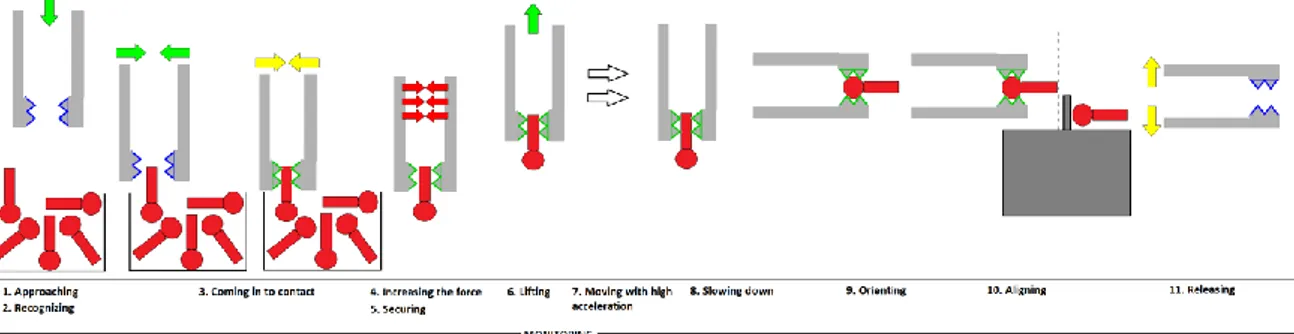
The grasping process, in a standard pick and place operation, can be divided into 6 steps, as showed in Figure .
For an easier understanding we used a scheme that represents a common jaw gripper, but the steps can be easily adapted to any other kind of gripper, even if contactless.
Figure 1 - Grasping process in a standard pick and place operation [50]
Approaching: the gripper moves towards the object and then slows down to align as precise as possible.
Coming into contact: the gripper goes nearby the object and comes into contact with the object surface;
11
Increasing the force and securing: the gripper closes its fingers (in the case of a jaw gripper) until it ensured enough grasping force (a force sensor increases precision);
Moving/processing: the gripper moves the part from its initial position to the destination; during the manipulation more or less acceleration can be used, according to the requirements: the more acceleration, the more grasping force is required;
Releasing process: as discussed in the previous paragraph, the releasing could be achieved following different strategies that are mainly divided in the ones that can be applied in micro scale and the ones that can be applied in macro scale.
12
2.1.2 Feeding
Reliable feeding is a key factor in automatic handling of work pieces. How an object is fed will determine the quality, the reliability and even the feasibility of the grasp.
Figure 2 - Different feeding scenarios [75]
As shown in Figure , a work piece fed by an automatic feeder is much easier to pick, compared to picking it inside a box with other pieces. Therefore the factors that are influenced by feeding can be summarized in:
Orientation: which could be random or predetermined;
Distance from other pieces: an object too close to another can make the grasp harder;
Relation with other pieces: the object, for instance, could be tangled with other work pieces;
In general, during assembly, work pieces, in order to be easily grasped, should be fed by an automatic feeder but, parts that present particular automatic feeding problems, are unlikely to be candidates for automatic feeding and will probably represent a harder grasp. For example, if parts tend to tangle or nest when in bulk, they will need a special-purpose feeding system to be handled [8] or a redesign in order to avoid the problem of tangling or nesting [9].
13 However, there can be other problems when dealing with mixed non-rigid objects which are less suitable for automatic feeding, for example thin flexible lines can easily lead to entanglement.
2.1.3 Cross issues
A very significant issue in the grasping process is, as stated before, that is strictly linked with how the work piece is fed, how it has to be handled and how it has to be positioned and released as shown in figure 3.
Figure 3 - Cross issues
Figure 3 clearly shows how the grasping process becomes harder when the operation is not a simple pick and place and includes other variables, such as:
Picking from random position: the gripper has to be equipped with a visual system that helps the object, and its orientation state, recognition;
Increasing the acceleration: higher acceleration requires higher grasping force and may exclude some grasping strategies;
Aligning: the gripper, and the robot which manages it, must have sufficient positioning precision;
14
Orienting: the gripper must be capable of orienting a work piece, and the work piece itself has to be easily adjustable;
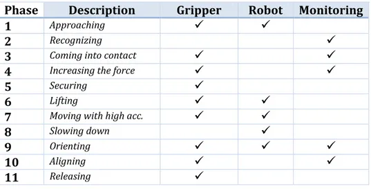
Phase Description Gripper Robot Monitoring
1 Approaching
2 Recognizing
3 Coming into contact 4 Increasing the force
5 Securing
6 Lifting
7 Moving with high acc.
8 Slowing down
9 Orienting
10 Aligning
11 Releasing Figure 4 - Phases details
Figure 4 resumes how not only the gripper is involved in the operation, but even the robot and the monitoring system affect the capability to efficiently complete the operation. A tick represents when the gripper, the robot or the monitoring system are involved in the corresponding phase of the operation.
In order to clearly show the implications of what has just being discussed on the different grasping principles, a further example has been proposed.
If we consider three different grippers, based on three different grasping principles (Bernoulli, magnetic and vacuum), they are all capable to manage the operation of a standard pick and place of a common thin sheet of metal, but if the feeding and the positioning are changed, not every gripper will be able to manage the operation.
15 Figure 5 - CASE 1 - pick and place
In this scenario, all three grippers are able to complete the operation.
Figure 6 - CASE 2 - pick from a stack and then place
In case 2, the feeding system has been changed, the sheets of metal are stacked. In this case the magnetic gripper will have troubles in picking just one sheet of metal, and the same would happen for the other two grippers (Bernoulli and vacuum) in case of porous work pieces.
16 This is a clearly atypical situation for a sheet of metal, but it could be likely for a part such as a gear. In this case a magnetic gripper would have difficulty in picking just one sheet, the Bernoulli gripper would be able to pick only horizontal pieces, the vacuum gripper would be able to grasp the sheet only if it is not blocked by others. In any case, a sensor that helps the gripper to find the right coordinates to pick the object will be needed, since the object is in a random position. In this case the feeding played a key role since it reduced the number of available grippers and it implied a new requirement: a monitoring sensor.
Figure 8 - CASE 4 - pick, orient and then place in vertical position
In this last case the object needs to be oriented during the manipulation. The Bernoulli gripper is not able to orient it since the horizontal forces will drop down the object.
These examples have been made to demonstrate how feeding, grasping, handling and positioning are linked together. Another example could be made repeating the first case with higher acceleration; in such case every gripper will need an higher grasping force, but the Bernoulli would not be able to hold the piece because the inertia forces will make it slip away.
17 Therefore all those aspects must be evaluated separately and only once we have evaluated correctly the effects on the various grasping principles, will it be possible to choose the ones that can correctly pick, handle and place the work piece.
However, since this expert system is focused on supporting the decision process that leads to the choice of the appropriate gripper, starting from qualitative parameters, the system could manage this problem from the opposite perspective, recommending how to feed the work piece in relation to the grasping principle (for instance for frictional grippers the recommended grasping direction will be given, which influences how the work piece should be fed).
18
2.2 G
RASPING PRINCIPLES:
A REVIEW OF THE LITERATUREGrippers are the end-effector of an industrial robot which provides temporary contact with the object to be grasped, ensuring its position and orientation. The grasp can be achieved in many different ways, depending mostly on the grasping principle.
Grippers belonging to the same category can be specifically designed to fit different pick and place operations, according to the properties of the object that has to be grasped. The reliability of the grasp is the main task and this is influenced from a significant number of parameters and their influence varies from grasping principle to grasping principle. Furthermore, when dealing with micro components1, the focus is
not only on the reliability of the grasp, which has still to be secure and robust, but even on the effectiveness of the release.
The figure summarizes the main grasping principles found in literature and the respective manageable object sizes.
Figure 9 – Grasping principles (from http://www.roblog.eu/)
19
2.2.1 Friction and jaw gripper
Friction and jaw grippers, usually seen in the form of two or three-fingered mechanical grippers, are a simpler model of the human hand which uses a clamping jaw-like system to grasp objects. These grippers possess fingers which usually move synchronously allowing an automatic object centering and ensuring a correct positioning and orientation; however independent jaw motion is also possible. The movement of the fingers can be achieved with many different pneumatic and electromagnetic prime movers.
The holding of an object can be done following two different methods:
1. Frictional grippers: Friction grip jaws rely totally on the force of the gripper to hold the part, the fingers must be capable of supplying sufficient grasping force to hold the work part. In order to avoid scratches on the work part and to improve the coefficient of friction, soft type pads are usually applied on the fingers;
2. Jaw grippers: jaws add stability and power by cradling the object, having the contact surfaces of the fingers designed according to the work part to adapt to the work part shape;
Furthermore, owing to the wide choice of available gear systems, there exists a very large diversity in design of such grippers in which translational or rotational motion is transformed into jaw motion as shown in Figure 10 - Some typical gripper mechanism for jaw motion [20].
20 Figure 10 - Some typical gripper mechanism for jaw motion [20]
The kind of motion influences the characteristics of the gripper, for example a gripper with parallel motion will be able to grasp a more wide range of objects, in terms of object size, but with less grasping force compared to a similar gripper using circular motion.
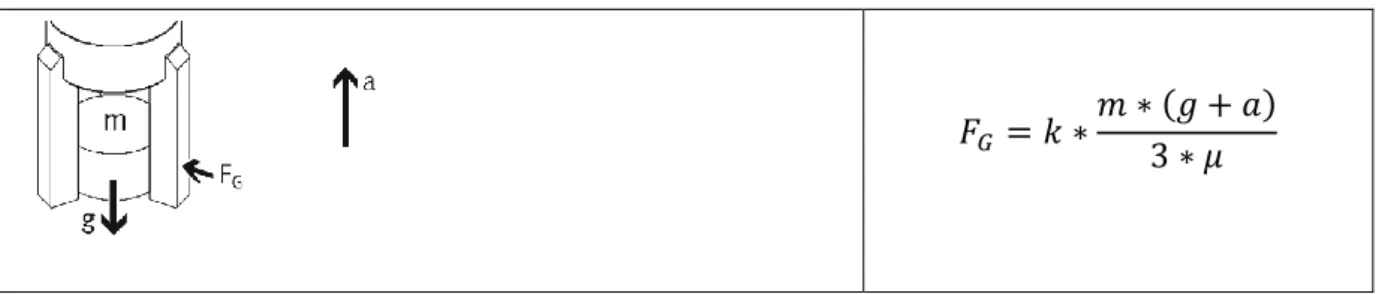
As just described frictional and jaw grippers can hold the object respectively with a mechanical locking or a frictional locking between the gripping surface and the work piece surface. In the following table [23] is summarized how the gripping force act in case of 2-jaw and 3-jaw grippers.
21 2-jaw grippers:
Mechanical locking
𝐹𝐺 = 𝐾 ∗ 𝑚 ∗ (𝑔 + 𝑎)
Mechanincal locking with V-Gripper
1. 𝐹𝐺 = 𝑘 ∗𝑚∗(𝑔+𝑎) 2 ∗ tan 𝛼 2. 𝐹𝐺 = 𝑘 ∗ 𝑚 ∗ (𝑔 + 𝑎) ∗ tan 𝛼 Frictional locking 𝐹𝐺 = 𝑘 ∗𝑚 ∗ (𝑔 + 𝑎) 2 ∗ 𝜇 ∗ sin 𝛼 3-jaw grippers: Mechanical locking 𝐹𝐺 = 𝐾 ∗ 𝑚 ∗ (𝑔 + 𝑎)
Mechanincal locking with V-Gripper
𝐹𝐺 = 𝑘 ∗𝑚 ∗ (𝑔 + 𝑎)
3 ∗ tan 𝛼
22 𝐹𝐺 = 𝑘 ∗𝑚 ∗ (𝑔 + 𝑎) 3 ∗ 𝜇 Where: 𝐹𝐺 = Gripping force 𝑚 =Mass 𝑔 = Gravitational acceleration 𝑎 = Gripper acceleration 𝜇 = Frictional coefficient
𝐾 = safety factor (usually at least 2)
Frictional and jaw grippers, using appropriate grasping forces and fingers (with different shapes and properties), can grasp a really large variety of objects, from micro to macro components and from very low to very high weights.
Furthermore, when specifically designed, they can handle even fragile objects thanks to pneumatic actuation and compliant soft fingers. In figure 10-11-12 some examples are shown.
23 Figure 12 – Compliant pneumatic gripper (Danish Technological Institute, Robot Technology)
Figure 13 - Compliant mechanical gripper (www.schunk.com)
Benefits
Stability: the grasp is very stable, the work piece once it is grasped cannot move between the fingers;
Automatic centering;
Low cost;
Frictional and jaw grippers, relying on the kind of fingers they are equipped, can grasp a wide range of objects;
Drawbacks
24
Slow material grasping: this kind of grippers needs to approach to the work piece slowly to avoid damages to the object, also the aperture and closure of the fingers has to be slow for the same reason;
Heavy weight: this affects the whole robot load capacity;
If not specifically designed to be compliant they can deform soft objects;
Grippers need to be specifically designed to be capable of handling fragile objects;
If not properly designed, since their grasping strategy is based on the contact with the object surface, there could be a risk of bacteria growth;
Their shape and weight create problems when operating in narrow spaces;
In case of jaw grippers a separate design is needed in order to handle different kind of objects.
This kind of gripper is also very common for many reasons such as ease of use, low cost, good dexterity and object stability.
25
2.2.2 Expansion gripper
Expansion grippers, which are also based on friction and form-fitting, ensure the grasp expanding an elastomer in the hole of objects having enough inside diameter. The expansion can be achieved in different way, depending on how the expansion gripper have been designed; usually is achieved through compressed air in the inner piston diameter of the elastomer which compresses increasing elastomer diameter and grasping the object thanks to the friction exercised on the inner walls of the work piece.
Figure 14 - Expansion gripper [50]
The grasped object has to be built specifically to be grasped with an expansion gripper, since every expansion gripper is designed to handle a very thin range of holes diameter with different grasping forces.
Furthermore the grasping force is controllable varying the pressure of the compressed air which is a must on this gripper since the force output depends on several other variables such as the diameter of the picked object, the surface finishing, friction and others.
26 The release is achieved by switching off the compressed air: the piston will return in its original position and the elastomer part to its original shape.
Benefits
Comes in handy when the contact surface is too small for using vacuum cups or other kinds of gripper;
It represent a very efficient solution for grasping small work pieces with holes;
The grasping force can be controlled with the input pressure making the same gripper capable of handling objects with very different weights;
The inflatable construction allows a multiple number of shapes to be handled with one model;
Drawbacks
It works only with objects having compatible holes;
The working range of a single gripper, in terms of dimension, is very limited since the grasping force is strictly linked to the diameter of the grasped object;
27
2.2.3 Magnetic gripper
The magnetic grippers, commonly used for grasping ferromagnetic materials, can be divided into two categories depending on the kind of magnet used.
Magnetic grippers with electromagnets
This kind of magnetic grippers needs a DC power in order to be activated and safely manipulate the object, this makes them more easy in controlling and releasing the object than magnetic grippers, mainly because they do not need an additional mechanism to release the object and the can be turned on and off. Anyway, if they do not implement an adequate safety system, they are more subject to unexpected object release in case of failure of the power source.
The magnetic field is generated by a wire wounded into a coil, when the electricity is passing through the wire the magnetic field becomes active and it deactivates when the electricity is gone.
Figure 15 - Electromagnetic gripper [20]
The grasping force can be calculated using the conventional electromagnetic formula:
28 Where:
B = Magnetic flux density;
I = Current trough conductor;
l = length of conductor
Magnetic grippers with permanent magnets
Figura 16 - grasping and releasing with a permanent magnet [20]
This kind of gripper does not require any sort of external power, as happens with the electromagnets, for handling the materials. After this gripper grasps an object, since it is not possible to turn off the grasping force, an appropriate releasing strategy is needed; usually the release is achieved through a mechanical switch (in the figure above: mechanical control of the magnetic flow), through air pressure or a specifically designed device.
Most of the magnetic grippers, using permanent magnets, which are currently available on the market are pneumatically actuated, but the most efficient are electrically actuated. It works similar to the electromagnets, where for activation and deactivation is necessary just a short electric pulse, but in this case the workpiece can be securely held in an emergency stop situations because it needs no DC power.
29 For specifically designed permanent magnets, typical retention pressure can be as high as 200kN/m2 [20].
A particular problem exists when a magnetic gripper has to grasp a single thin and flat object from a stack. Recently has been developed a magnetic array tool (Magswitch® patented) that uses multiple permanent magnets with different magnetic fields to create a very shallow depth of field to destack sheets up to 0.7 mm.
Benefits
It only requires one surface to ensure an effective grasp;
The grasping is done very quickly;
No power losses due to friction;
It does not require separate designs for handling different size of materials;
It is capable of grasping materials with very high porosity;
Usable with a wide range of object sizes and shapes;
Drawbacks
The gripper works only with ferromagnetic materials;
The grasped work piece has the chance of slipping out when it is moving quickly;
In case of electromagnetic gripper a failure of the power supply could lead to an almost immediate object release;
A permanent magnet gripper requires an additional release system which may lead to other problems (for example scratches or damages to the workpiece);
30
Due to permeating effects of the magnetic field, separation of thin objects may be very difficult even though recent studies showed a resolution of 0,7mm;
31
2.2.4 Vacuum gripper
Vacuum grippers are constituted by one or more cups inside which a vacuum level is created. The suction cups are connected through tubes with under pressure devices (like vacuum pumps, ejectors, suction bellows, pneumatic cylinders) for picking up items, for releasing items air is pumped out into the suction cups.
The following figure shows the most important functions and properties of a suction gripper.
Figura 17 - Properties of a suction gripper [23]
Generally, the suction cups are round shaped and usually developed by means of rubber or other elastic materials or soft plastics and can be used at temperatures between -40 and 200 °C depending on the material used. Moreover, the vacuum cups can be prepared of hard materials when dealing with the handling of soft material objects. Thereby vacuum cups designs vary upon specific object characteristics, such as surface roughness, toughness and shape.
The suction cup can be categorized into four different types as shown in Figure 18 - Different types of suction cups [7]-
32 Figure 18 - Different types of suction cups [7]
The vacuum can be created in two ways trough two different devices: venture device or vacuum pump, the first is a simpler device and it is also more reliable and inexpensive. Both devices can provide high vacuum if there with a sufficient supply of air pressure.
The following formula helps with the definition of the suction chamber and the size of the suction area in order to ensure a safe grasp.
𝐹 = (𝑝0− 𝑝𝑢) ∗ 𝐴 ∗ 𝑛3∗ 𝜂 ∗ 𝑧 ∗1 𝑆 Where:
𝐴 = Area of the suction cup;
𝐹 = Load;
𝑛3 = coefficient of deformation of the cup;
𝑝0 = atmospheric pressure;
𝑝𝑢 = pressure in seal suction chamber;
𝑆 = safety factor;
33
𝜂 = efficiency of system.
Vacuum grippers are largely diffused for moving objects of various natures (glass, marble, sacks, etc.). Vacuum suction is used extensively throughout the packaging industry, as well as most other fields of robotics. In addition to the advantage of producing an attraction force, vacuum grippers have a soft grasp even on large and heavy objects. Grippers based on vacuum forces also demonstrated their effectiveness in managing deformable and lightweight parts [86][87] without distortion, deformation or damage.
Vacuum grippers can grasp objects spacing from micro objects [61][65], which is still under development for rounded surfaces, to very large and heavy work pieces [62]. The constraint of this grasping principle is the need for a flat surface available for grasping, limit which has been recently overcome with a specific self-selecting Grasper [60] which is capable to handle regular rounded surfaces.
As happens with frictional grippers even vacuum grippers can be specifically designed to handle fragile objects; since the first limit in handling such object is the impossibility to use strong pressure on low contact area, recently such problems have been solved recurring to more than one cups with lower pressure or one bigger compliant cup such as the one showed in the figure above:
34 Figura 19 – Compliant vacuum gripper
Benefits
Can grasp very fragile objects, such as glass;
Very fast grasping and placing;
Configurable for variable geometries;
Drawbacks
Low precision;
For high grasping forces it needs a large grasping surface available;
It cannot grasp objects with high porosity;
Object with low porosity can still be grasped, but the grasp is not energy efficient;
Needs a flat surface to ensure a safe grasp;
Very loud;
35
2.2.5 Electrostatic gripper
Electrostatic fields, like their magnetic counterparts, can be used to provide an astrictive force, known as electroadhesion. Such grippers are mainly used to grasp micro objects where the surface related forces start to dominate over the volume related.
Electrostatic micro grippers consist of electrodes where an applied voltage generates an electric field. Dependent on the material properties of the objects to be handled either a homogeneous or an inhomogeneous field distribution is needed to generate a grasping force.
Electrostatic forces in parallel plates can be described as in the following equation:
𝐹 =1 2∗ 𝜀0𝜀𝑟∗ 𝑆 ∗ 𝑉2 𝑑2 Where: S = Contact area; V = Applied potential; d = separation distance;
𝜀0 = free space permittivity;
𝜀𝑟 = dielectric constant.
DC electric fields have been used for handling micro parts [55], aligning optical fibers [56], positioning and aligning micro components [57], feeding mini flat plates [58] or micro parts [21], moving a microprobe, and even transporting bubbles in microgravity
36 [59]. Furthermore recent searches have shown a highly flexible electrostatic gripper systemwhich has been developed at Fraunhofer IPT.
Figura 20 - Electrostatic gripper developed at IPT.
It is capable of lifting semi-finished textile products made of carbon fibers and other materials and putting them down again with pin-point accuracy, without damaging them.
In particular, electrostatic forces comes in handy when traditional contact approaches fail in handling fragile, polished, or coated optical micro parts. Such parts can be damaged, for example, by friction-based grippers or could present features that can be broken by contact pressure or might have to be manipulated in particular environments where suction grippers cannot be applied (for example, in vacuum) [21].
Benefits
Works in particular environment (such as vacuum);
Does not damage or scratch fragile objects;
Works with high porosity objects;
Can handle all metals, whether ferrous or non-ferrous.
Drawbacks
37
Very sensible to the humidity changing of the environment [63], not very reliable with an high humidity rate[1];
Requires dust-free environment;
Can’t grasp wet objects;
38
2.2.6 Bernoulli Gripper
Bernoulli gripper relies on the Bernoulli airflow principle which states that when the speed of a moving fluid, which can be liquid or gas, increases, the pressure within the fluid decreases.
A Bernoulli gripper can grasp an object with the under pressure made by the high velocity airflow from the noodle to the surface of the object. If the force created by the under pressure exceeds the weight of the object it will be grasped by the gripper.
Figure 21- Bernoulli gripper[13] The grasping force can be described by the formula below.
𝐹𝑔 = 𝐹𝑙− 𝐹𝑟 𝐹𝑙= 1 2𝜌 𝑄2 2𝜋ℎ2[ln 𝑟𝑒𝑥𝑡 𝑟𝑖𝑛𝑡 −1 2 (𝑟𝑒𝑥𝑡2 − 𝑟 𝑖𝑛𝑡2 ) 𝑟𝑒𝑥𝑡2 ] 𝐹𝑟 = 𝜌 𝑄 2 𝜋𝑟𝑖𝑛𝑡2
39 Where:
𝐹𝑙 = lifting force;
𝐹𝑟 = repulsion force;
𝑄 = volumetric flow rate;
𝜌 = air density;
ℎ, 𝑟𝑖𝑛𝑡, 𝑟𝑒𝑥𝑡 are shown in Figure 21- Bernoulli gripper[13];
Such grippers are typically used with small and light rigid products such as silicon wafers and circuit boards, recent studies also demonstrates their effectiveness in grasping leather plies [13] and sliced fruit and vegetables [38].
When high speed operations are involved the grasped object needs to touch the gripper slightly to overcome inertia forces with static friction [65].
Benefits
No imprinting on delicate surfaces;
Contactless handling;
No contamination of and from the gripper;
In sliced fruit and vegetables it can remove surface moisture produced during slicing [22];
Drawbacks
The gripper will drop the work piece if significant lateral force is applied;
Loose effectiveness and reliability when dealing with porous surfaces;
40
2.2.7 Van der Waals gripper
A Van der Waals gripper is based on the Van der Waals forces which are short range forces, acting when surfaces are sufficiently close together, and are due to spontaneous electrical and magnetic polarizations that cause a fluctuating electromagnetic field within the medium and the gap between the surfaces[73][74].
This kind of gripper is used especially in micro-manufacturing because of its relatively low gripping forces but since this grasping principle is based on one of the predominant forces which act on micro components2, this introduces problems in releasing [27]. The
challenge is then how to release the micro-material since the Van der Waals forces have an adhesive effect when particles are in contact, many studies have addressed this problem in different ways (it can be a separate device, mechanism or a specific physical design) with different benefits and drawbacks [26][72][31]. Even if this grasping principle is mainly adopted in micro-manufacturing, recent studies demonstrates its effectiveness even when heavy loads are involved.
A gripper, relying on Van der Waals forces, can pick an object when the surfaces of the gripper and of the work piece are sufficiently close together to generate enough gripping force following this equation [28]:
𝐹 =𝐴𝐻𝑌
𝑋
6𝐷𝑛
Where:
2 Gravity dominates in macroscale but, when dealing with micro-components, forces like Van der Walls forces,
41
𝐴𝐻 = Hamaker coefficient, which depends on the kind of material;
𝐷 = shortest surface distance;
𝑛 and 𝑋 are two exponent, greater than zero, that vary with the geometry of the grasped object;
𝑌 = dimensional parameter of the micro-material under consideration;
Van der Waals forces are also dependent on the shape or geometry of the interacting substances [29][30] , making this kind of gripper not suitable without a planar surface available, as shown in the following table:
Geometry Force
Two flat surfaces
𝑓 = − 𝐴𝐻 6𝜋𝐷3 𝑝𝑒𝑟 𝑢𝑛𝑖𝑡 𝑎𝑟𝑒𝑎 Two spheres 𝐹 = − 𝐴𝐻 6𝐷2 𝑅1𝑅2 𝑅1+ 𝑅2 Sphere-flat surface 𝐹 = −𝐴𝐻𝑅 6𝐷2 Cone-flat surface 𝐹 = −𝐴𝐻tan 2𝜙 6𝐷 Cylinder-flat surface 𝐹 = −𝐴𝐻𝑅 2 6𝐷3 Where:
𝑅 = radius of the sphere or the cylinder;
𝜙 = half cone angle.
The table also clearly shows how the Van der Waals forces are not only depending on the distance between two surfaces, but also on the surface area available.
Recent studies also demonstrated how the surface roughness of the work piece can influence the manipulation capability of this kind of gripper: surfaces with higher
42 roughness were found to be suitable for the pick-up position, and those with low roughness for the placement position in an effective material handling system[26].
Figura 22 - Van der Waals grippers - a) Polyurethane gripper [72] b) Festo – Nano Force Gripper
Benefits
It needs a very low amount of energy for grasping and no energy for holding;
It is very suitable for fragile objects;
Drawbacks
It is greatly influenced by the superficial treatment of the object surface;
Depending on the gripper geometry it may require an additional release system;
It is not suitable with very rough surfaces[26];
43
2.2.8 Needle gripper
This kind of grippers are very suitable for the handling of tissues or food. Their structure is quite simple and they can manage to grab a tissue very well without leaving significant traces on it.
In particular in fish industry a needle gripper is very suitable since others, like frictional, to avoid damages to the grasped objects needs a soft grip which requires tactile sensing which still is slow in action, expensive and not suitable for the demanding environment in the fish processing industry [75].
Figure 23 - Gjerstad needle gripper
The grasping elements are the needles, which can be classified into two groups depending on which are rigid, or flexible depending on the requirements of the grasp. In particular, during the movement of the gripper, rigid needles are not subjected to deform, while flexible needles deform because of their low relative stiffness, compared to that longitudinal axis of the tissue that is grasped.
Figure 24- Needle gripper[12]
44 𝐹 = 𝐸𝑧𝑥𝛿
2𝑆𝑠𝑖𝑛𝛼𝑁 Where:
𝐸𝑍𝑥 = Modulus of elasticity of a fabric with x% extension;
𝛼 = penetrating angle;
𝛿 = layer thickness;
𝑆 = distance of needles;
Benefits
Can handle very flexible objects;
Fast action;
Variable geometry grip;
Drawbacks
Pieces with soft texture require lower acceleration to maintain surface quality[75];
Cannot be used with very fragile objects;
The object has to be permeable;
45
2.2.9 Capillary Gripper
A capillary gripper takes advantage of the surface tension forces provided by a liquid droplet used as an interface between two surfaces. Those forces, compared to gravity, are relevant in micro-component handling and the higher is the viscosity of the fluid, the higher will be the gripping force.
In micro assembly, surface tension gripping has been introduced in the late ’90 for the purpose of gripping millimetric silicon chips and from then it has found many applications to grasp various kind of objects of different size and have been used owing to their flexibility and reliability [34][36][85].
Figure 25 - Capillary micro gripper[37]
The grasp is achieved with a combination of capillary and cohesive forces [32] as shown in the following equation [20] of the lifting force:
𝐹 = 𝑝𝑘𝜋𝑎2𝜓
46 Where:
𝛾 = suface tension;
𝑝𝑘 = capillary pressure;
𝑎 = gap width;
𝑎𝜓0 = radius of the fluid bridge;
Figure 26 - example of capillary gripper [38]
In order to achieve the release, other than the general micro components releasing methods already discussed, many different strategies can be followed [33] as showed in the following table:
47 Figura 27- Releasing strategies related to capillary grasping [33]
Another possibility to achieve a release is using a solvent like ethanol, or it can be done waiting the liquid interface to evaporate, but it is a much slower release and its speed is usually unacceptable.
48 Furthermore recent studies [38] also shown a new releasing system where the work piece is released by squeezing the liquid bridge and obtaining a variation of the wetted surface which implies a drastic reduction of the gripping force.
Benefits
Energy efficient;
Can grasp components with only one upper free surface available;
Needs only a small available grasping area;
Has no limitations in terms of material and shape;
compliant behavior and a self-centering effect due to surface tension;
capability of grasping delicate components as the meniscus between the gripper and the object has a ‘‘bumper’’ effect;
Drawbacks
It implies the use of liquid;
Dust particles may stick to the liquid;
49
2.2.10 Acoustic gripper
The acoustic gripper overcomes the surface forces by levitating the handled component, being a contactless gripper it also avoids the release problems in micro manufacturing related to adhesion forces between the gripper and the work piece.
Two configurations can be found in literature [43]: standing wave levitation and near-field levitation.
Figure 28 - Different configuration of acoustic levitation [44]
Standing wave levitation
In standing wave levitation the component stays, in the nodes of an acoustical standing wave, between a vibrating plate and a reflector. This configuration can lift particles with low weights (few grams) [44] which can be greatly increased if working in special environment (liquid or microgravity). A gripper based on this configuration can also achieve precise positioning and orientation by moving the reflector or changing the node position.
If a standing wave pattern is generated between the transducer and the reflector, by placing the reflector at an appropriate distance from the transducer, parts can be suspended in a stable position into the acoustic levitator. Positioning forces, acting in the direction of the pressure nodes, holds a part in balance below a node, as the axial
50 components of the levitation forces acting on all sides of the body compensate for the weight of the sample as shown in the following figure.
Figure 29 - Levitation of a water drop in a standing wave [47]
Near-field levitation
Near field levitations lifts flat planar objects through an high intensity ultrasonic transducer. The lifting height is quite small compared to the standing wave levitation but this configuration can reach much higher lifting forces and, depending on the transducer used and the gripper configuration, it can lift any weight if the separation distance is small enough and the shape, which has to be flat, offers enough planar surface available [47][48].
51 Figure 30 - Levitation force as a function of levitation distance [48]
Benefits
Any kind of material can be lifted;
Standing wave gripper can achieve precise positioning and orienting of the lifted object;
Drawbacks
Slight asymmetries in the acoustically induced convective flow field can lead to imprecise positioning or uncontrolled object rotations[44];
In near field levitation the object must be flat and preferably thin while standing wave can lift only small an light objects;
52
2.2.11 Solid-liquid state gripper
This kind of grippers are based on the principle that the adhesion power of an intermediate (which can be, for instance, water) in its solid state is greater than in its liquid state.
The grasping process starts with a liquid droplet between the gripper and the surface of the work piece, subsequently the droplet is frozen and its adhesive power will ensure the grasp.
The release, as well as the known releasing strategies of adhesive micro grippers, can also happen by breaking the frozen material that holds the object, one of the most common releasing strategies adopted with thermal grippers is the use of a micro heater; other strategies are discussed in 2.4.
The following images show two different kind of ice grippers, one based on thermoelectric effect [41] and the other based on the principle of the reversible thermal flow gripper achieved with a Peltier element [76].
53 Figure 32 - Gripper configuration
Benefits
Can hold different shapes;
Can manage fragile objects;
Drawbacks
Low grasping force;
Does not work underwater;
Low positioning precision when releasing micro objects;
Can damage wet objects;
Melting the object surface is not always feasible;
Requires the object to be not sensitive to liquid;
Water or brine Q Q Heat transfer back plate Stainless steel gripper surface Gripped meat
Housing Robot interface plate
Cooling fins Insulation 1 0 Peltier element brine or Water
54
2.2.12 Laser gripper
The optical (laser) gripper is a contactless gripper based on optical levitation [42] which states that particles can be freely suspended and accelerated by the forces of radiation pressure from visible laser light.
Figure 33 - Force components of a laser beam
The focused laser source can produce enough pressure to lift only very small micro components since the gripping force hardly reaches 1𝑛𝑁 [45]. Anyway, to compensate the small grasping force, the operation may take place in a liquid
Benefits
Contactless gripping;
Very suitable for nano parts;
Drawbacks
Thermal effects on the work piece;
Very low gripping forces relegate this gripper only to very low weight component grasping;
The material needs to have an higher refractive index than that of the surrounding medium;
55
2.3 H
YBRID GRIPPERSIn the last years have been developed some grippers which does not fit in just one of the category described above and are called “hybrid grippers”.
In this paragraph are described some examples of such grippers.
Jamming gripper
It is an extremely flexible gripper since it can grasp almost every kind of object, such as objects with strange shapes, fragile, with high porosity, without any flat surface suitable for grasping etc…
Figure 34 - Jamming gripper (from http://www.roblog.eu/)
The grasp is made taking advantage of friction, vacuum, compliant gripper shape and it can be soft thanks to the distributed and not localized pressure on the grasped object.
Anyway, this gripper has its drawbacks since it cannot center the object and the positioning is very inaccurate.
56
Electro adhesive frictional gripper
The gripper developed by SRI international is based on several principles: electroadhesion, friction and compliancy.
Figure 35 - SRI gripper (http://www.sri.com)
SRI electroadhesion technology allows electrically controlled reversible adhesion to most surfaces thanks to the compliance of the gripper fingers.
When alternate positive and negative charges are induced on adjacent electrodes, the electric field sets up opposite charges on the substrate and thus causes electrostatic adhesion between the electrodes and the induced charges on the substrate; thanks to the compliance the distance between the electrodes and the grasped object is extremely reduced and this results in more grasping force.
Experiments demonstrated how this gripper can adhere to numerous surfaces such as wood, drywall, paper, glass, concrete, and metals.
57
Contact Bernoulli gripper
This gripper, which is still under development, is not properly a hybrid gripper, since does not belong to more than one grasping principle, but it is not even a just a Bernoulli gripper since it is not contactless.
Figure 36 - Contact Bernoulli gripper Errore. L'origine riferimento non è stata trovata.
Standard Bernoulli grippers would not be able to grasp an object which has not a flat surface available for grasping, while the one showed in the figure above can thanks to its capability to conform its shape on the object surface.
In this case deformable surface has been used to reduce the mean distance between the gripper and the object. The air is pumped through a series of needles and the lift force generated, thanks to the compliance of the gripper’s shape, on non-flat surfaces has a significant increment.
Anyway there are still significant drawbacks since it cannot handle fragile or flexible objects due to the necessity to conform its shape through the contact with the object surface.
58
2.4 R
ELEASING STRATEGIES:
A REVIEW OF THE LITERATURESince the most valuable parameter in releasing is the object dimension, releasing strategies can be divided into two categories: releasing strategies in macro scale and releasing strategies in micro scale.
2.4.1 Macro scale
In macro scale the release is mostly achieved through switching off the grasping forces and letting the gravity forces release the object.
However, this is not always possible and in some cases (e.g. a magnetic gripper which uses a permanent magnet) a separate device or mechanism is needed. The mechanism dedicated to the release has to be compatible not only with the gripper itself, but with the object characteristics as well. In particular, when an object is fragile, pushing it down with a separate device could damage the object, or could smear it if the part is sensitive to stain. Other than the object characteristics, another parameter that influences the choice of the appropriate releasing strategy is the positioning precision needed.
Since in macro scale there is not enough literature concerning releasing strategies, probably because other releasing strategies beside gravity represent a rare task (with the exception of permanent magnet), it is hard to suggest with sufficient reliability any specific releasing strategy; however, it is still possible to suggest when a dedicated mechanism is required and highlight when it should be compatible when particular object characteristics.
59
2.4.2 Micro scale
In micro scale, with the exception of a few contactless grippers (e.g.: Bernoulli, laser and standing waves acoustic grippers), the literature shows how the main problem of the contact ones (friction and jaw grippers, vacuum gripper, Van der Waals etc.) concerns the releasing task [33].
Following the work of Fantoni and Porta, which reviews the releasing strategies in micro parts handling, the releasing strategies can be mainly divided into two groups [33]:
1. Passive releasing strategies: where the reduction of the surface forces is obtained without the use of external forces. In this case environmental conditions can reduce the principal forces acting at micro scale (electrostatic, adhesion, Van der Waals) or the strategy could be focused on exploiting some micro gripper features (in terms of shape, surface coating and material);
2. Active releasing strategies: where an additional action allows the gripper to release the object. These additional actions can be forces able to overcome the adhesive ones between gripper and object, or means to reduce the contact area;
The following tables report more details about the releasing strategies, providing the corresponding link with literature, a brief description, a scheme and the kind of forces involved.
60
Type Principle Scheme Description Force
G
rip
p
er
Condutive material/coatings –grounded gripperConductive materials or coatings (which do not form insulating oxides) reduce static charges. Grounded grippers prevent the charge storage. [79][19]
electrostatic
Low difference of EV potential
Gripper and object made of materials with a small potential difference reduce “contact interaction” forces. [19]
electrostatic
Hydrophobic coating
Hydrophobic coating reduces surface tension effects; it prevents the adsorption of moisture. [102]
surface tension
Low Hamaker constant coating
Low Hamaker constant coating reduces Van der Waals forces. [79]
Van der Waals
Hard materials
Contact pressure causes deformations, increasing the contact area between gripper and object: grippers made of hard material have to be preferred. [19]
Van der Waals, electrostatic
Rough surface – Micro pyramids
The gripper roughness reduces the contact area and sharp edges induce the self discharge effect. [19] [102]
Van der Waals, electrostatic
Spherical fingers
Spherical fingers reduce the contact area in comparison with planar ones. [19]
Van der Waals, surface tension
Envir
o
nme
nt
Dry atmospherea dry atmosphere reduces surface tension effects (but increases the risk of triboelectrification and the generation of electrostatic force) [19] [79]
surface tension
Vacuum
if no moisture affects the contact, there is no liquid bridge and so surface tension is reduced (but with risk of triboelectrification) [19]
surface tension
No O2 in the environment
if there is no oxygen, native oxide cannot arise on the surface of the gripper/handled objects [19]
electrostatic
in fluid releasing
Assembly in fluid eliminates surface tension effects and reduces electrostatic forces [19] [101]
electrostatic, surface tension
Ionized air
Ionized air can neutralize free charges on the surfaces and so it reduces electrostatic forces [6]
electrostatic Figure 38 – Passive releasing strategies [33]
61
Type Principle Scheme Description Problems Released components Fo rc e s Air pressure 1.Direct 2.Indirect (Adsorption force)
1. An air pressure flow [6][10]overcomes adhesion forces; 2. By heating a suitable end effector the object is released thanks to the ad-sorption force [103] Possible lack of precision in the re-leasing place 1. 50-300μm parts [6]; square silicon chips (4.2*4.2*0.5mm3) of 20.5mg; [104]; 2. Max. adsorption force 0.22μN [103] Acceleration Or vibration
An acceleration or a vibration given to the gripper support allows the object to be detached thanks to inertial forces [105][106]
Possible lack of precision in the re-leasing place [106] 40μm pollen micro spheres [105]; 400μm spherical and 900μm half spherical lenses [106] Micro heater 1.Evaporating moisture/liquid 2.Melting ice
1. A micro heater reduces the moisture-liquid (so surface tension-capillary forces) [79]; 2. Melting of ice (ice gripper) [77][82]
Temperature sensitive parts can be damaged by heat SMD plastic elements, small copper coils for telecommunication [77] Electrostatic force control 1.Shorting the gripper 2.Voltage tuning 3.Inverting polarity
Parts are released by the electrostatic force control:
1. Shorting down the gripper electrodes [79]; 2. Tuning the electrostatic force between gripper and substrate [107] ; 3. Inverting the polarity [108][21]
Problem in releasing conductive components [18] 2. Metallic spheres of d=30μm [107]; 3. Spheres of d=100-800μm and cubic valve (l=l80μm) [108]; Spheres, cylinders of 300-1000μm [18] Different adhesion force 1.Adhesion on substrate 2.Different adhesion tools 3.Different volume of liquid
Objects pass from a tool A to a tool B exploiting the difference in adhesion force between the tools and the object. The tool B can be: 1. A substrate [108]; 2. A gripper [105]; 3. The force difference can be given by different volume of the same liquid [109]
The object has to be detached from the tool B (if the releasing place on tool B is not the final place) 1. Glass spheres with d=100-800μm and cubic valve flap with edge l80μm [108]; 2. 40μm pollen microspheres [105] Engagement by the substrate/ tool 1.Snap 2.Against edge 3.Scraping 4.Rolling 5.Needle
The object is released by its mechanical engagement on the substrate [104] or an-other tool. This strategy includes: 1. The use of snaps [110]; 2. Part against an edge [111]; 3. Scraping [105]; 4. Rolling [105]; 5. Use of needle [104] Often additional features on the substrate are required 2. Metallic/non metallic parts of 50-300μm [6]; 4. 40μm pollen microspheres [105]; 5. Square silicon chips (4.2*4.2*0.5mm3) of 20.5mg; [104] Gluing on substrate Parts are released by gluing them on the
deposal place [104]
Not suit-able for moving parts
Square silicon chips (4.2*4.2*0.5mm3) of 20.5mg; [104] 3D handling of the gripper 1.Variation the curvature 2.Tilting
A decreasing of the contact area through: 1. Varying the gripper curvature from a flat shape to a curved one [112]; 2. Tilting the gripper [113]; 3. Parallel motion of the gripper respect to the substrate [114]
Complex 3D handling of the gripper. Many DOF required. 1. Minimum object weight 98mg [112]; 2. Metallic spheres of d=20-30μm [113]; 3. 40μm
62
3.Parallel motion pollen
microspheres [105]
Additional tool
An additional tool (with little contact area with the object) allows the object to be first detached from the gripper [113], then released on the substrate by removing the tool Many de-vices in a small space Metallic spheres with diameter of 20-30μm [113]
Roughness change The roughness change reduces adhesion forces al-lowing the part to be released [79]
Difficulties in realization
Electrowetting The modification of the liquid drop by an electro-static field reduces the contact area
Difficulties in meniscus control Figure 39 - Active releasing strategies [33]
The tables classify one by one the releasing strategies in micro scale, however it is not uncommon that releasing strategies use more than one approach at the same time.
This classification scheme is necessary to verify the matching couples of releasing strategies and grasping principles.
In the following table the compatible couples are listed.
Passive releasing strategies Active Releasing strategies
Gripper Env Forces Contact area r.
Co n d . m at/ co at - gr o u n d e d g r. Low d iff e re n ce o f E V p o te n ti al H yd ro p h o b ic c o ating Low Ham ake r c o n stan t co ati n g H ar d m ate ri al s R o u gh su rface Sp h e ri cal fi n ge rs D ry at m o sp h e re Ion ize d air A ir p re ssur e ( d ir e ct/ in d ir e ct) A cc e le ration o r vi b ration M ic ro h e ate r El e ctr o stat ic fo rc e c o n tr o l D if fer e n t ad h e si o n fo rc e En gag e m e n t b y su b str ate /to o l Gl u in g o n t h e su b str ate 3D h an d lin g o f th e gr ip p e r A d d ition al t o o l R o u gh n e ss c h an ge El e ctr o we tt in g Grasping P. Friction Ice Van der Waals Electrostatic Capillary Suction
63 Therefore choosing the appropriate releasing strategy is a matter of compatibility between grasping principles and releasing strategies; the selection of the available grasping principles is achieved according to the object characteristics and the kind of operation in which the work piece is involved; the same happens with the choice of the available releasing strategies.
Fantoni and Porta list which object characteristics make a releasing principle or a releasing strategy not available. Their work has been integrated in relation with the object characteristics identified in 3.4 and then translated as exclusion rules (3.5).
64
2.5 G
RIPPERS CHARACTERISTICSThe technical properties of a gripper and its price are the basis for an assessment of its suitability for a given application and a comparison with other makers’ products.
The suitability of a gripper is then defined by how it satisfies the requirements of the operation. Every gripper has a “range” of acceptability for its technical characteristics (e.g. a range of manageable dimensions, manageable weights, shapes etc…).
The choice of the proper gripper must start with a study of the planned application, as discussed before this involves object characteristics, feeding system, environmental characteristics and handling characteristics.
Hence, the choice of the right gripper can be made when gripper technical characteristics are adequately defined; Festo, one of the major manufacturers, summarizes the fundamental technical data that defines the specifics of a gripper as shown in Figure 42 - Festo - Characteristic data for grippersfigure 42.
Festo divides into three steps the examination of the gripper suitability:
1. Assign to every characteristic a weight3;
2. Check the primary characteristics;
3. Use the secondary data to make a final selection.
3 For every given application a determinate characteristic could have different relief, one example is the
closing and opening times, when speed is not a requirement their weight should be less compared to more important characteristics.
65 Figure 42 - Festo - Characteristic data for grippers
Furthermore, the focus should not be only on which characteristics are fundamental for defining a gripper’s field of application, but also how they are measured to be able to compare one gripper with another.
Finally, if we take a closer look to the work of Festo, it is possible to notice that his characteristics parameters are particularly focused on frictional grippers and do not take in account the reliability of a gripper with specific object characteristics.
66
3
E
XPERT SYSTEM
3.1 C
URRENTLY AVAILABLE SUPPORT SYSTEMSAn expert system could be defined as a computerized system that emulates the decision-making ability of a human expert.
Actually, only some of the major grippers’ manufacturers (e.g. Festo and Schunk) released a software that helps the user through the selection of the gripper, but this software is focused on just one grasping principle (usually frictional) and relies on strong initial conditions.
Recent studies [90][91] focused mostly on micro-components grasping, establishing a correlation between micro-assembly techniques and part features.
In this paragraph we summarize and analyze two very different approaches: the Festo gripper configurator and the work of Antonelli, Fantoni, Porta and Santochi about the selection of the appropriate micro-assembly technique.
![Figure 1 - Grasping process in a standard pick and place operation [50]](https://thumb-eu.123doks.com/thumbv2/123dokorg/7622746.116385/10.892.136.782.571.825/figure-grasping-process-standard-pick-place-operation.webp)
![Figure 10 - Some typical gripper mechanism for jaw motion [20]](https://thumb-eu.123doks.com/thumbv2/123dokorg/7622746.116385/20.892.276.637.115.441/figure-typical-gripper-mechanism-jaw-motion.webp)
![Figura 22 - Van der Waals grippers - a) Polyurethane gripper [72] b) Festo – Nano Force Gripper](https://thumb-eu.123doks.com/thumbv2/123dokorg/7622746.116385/42.892.279.635.219.400/figura-waals-grippers-polyurethane-gripper-festo-force-gripper.webp)
![Figura 27- Releasing strategies related to capillary grasping [33]](https://thumb-eu.123doks.com/thumbv2/123dokorg/7622746.116385/47.892.215.708.118.858/figura-releasing-strategies-related-capillary-grasping.webp)
![Figure 29 - Levitation of a water drop in a standing wave [47]](https://thumb-eu.123doks.com/thumbv2/123dokorg/7622746.116385/50.892.274.638.275.550/figure-levitation-water-drop-standing-wave.webp)

