Computational Aeroelasticity with CFD
models
Luca Cavagna, Giuseppe Quaranta, Sergio Ricci, Alessandro
Scotti
Politecnico di Milano, Dipartimento di Ingegneria Aerospaziale
Abstract
Questo articolo fornisce una presentazione generale delle procedure numeriche che sono oggigiorno usate al Dipartimento di Ingegneria Aerospaziale del Politecnico di Milano per la aeroelasticità computazionale mediante complessi modelli di Fluidodinamica Computazionale (CFD). Nell’articolo vengono a grandi linee descritti due principali programmi di ricerca: la progettazione di un sistema di soppressione di flutter per l’ala a freccia negativa del dimostratore aeroelastico X-DIA, la valutazione del flutter transonico e le analisi di aeroelasticità statica per aeromobili ad alta velocità. Entrambe le ricerche richiedono modelli di fluido complessi ed accurati, basati sulle equazioni di Eulero o Navier-Stokes, per studiare correttamente i fenomeni di Interazione Struttura-Fluido (FSI). Per il primo caso, al fine di definire correttamente l'efficacia delle superfici di controllo e i relativi effetti viscosi, sono richieste una accurata descrizione del carico di pressione e dei momenti di cerniera; per il secondo caso, al fine di superare in questo regime di velocità le lacune delle teorie classiche basate sul potenziale linearizzato, è necessario studiare l’influenza dell’onda d’urto sui meccanismi di flutter e sul campo di pressione.
This paper gives an overview of the numerical procedures which are nowadays used at Dipartimento di Ingegneria Aerospaziale Politecnico di Milano for computational aeroelasticity by means of complex Computational Fluid Dynamics (CFD) models. Two main research programs are here outlined: the design of a flutter suppression system for the forward swept wing of the in-house aeroelastic demonstrator X-DIA, and the transonic flutter assessment and static aeroelasticity analyses for high-speed aircrafts. Both of them require an accurate and complex fluid models based on Euler or Navier-Stokes equations, to correctly investigate Fluid Structure Interaction (FSI) phenomena. For the first case, an accurate description of the pressure load and the hinge-line moments are required to correctly define control surfaces effectiveness and related viscous effects; for the second case the adoption it is necessary to investigate shock-wave influence on flutter mechanisms and pressure-field to overcome the lack of the classic linearized potential theories in this speed-regime.
Keywords: Computational Fluid Dynamics, Aeroelasticity, Unsteady Aerodynamics, Grid Motion.
Introduction
This article introduces an aeroelastic procedure for (FSI) problems modelling, based on the integration of different commercial software. Far more computational resources than those used in the classic approach are required to solve the dynamic equations of the computational fluid dynamics. Therefore, particular attention is paid in order to define a strategy making the whole process efficient and well-suited for the realistic industrial environment problems. Current hardware resources, combined with the availability of specific software for structural and fluid dynamics analysis make the time mature for
extending Computational Aeroelasticity (CA) beyond the academic research environment, without using a specifically developed code.
The procedure of analysis used here is based on a user-defined plug-in named NAEMO-CFD (Numerical AeroElastic MOdeller with CFD models) running under the CFD solver
FLUENT© which is enhanced with the
capability of carrying out different kind of static and dynamic aeroelastic computations. The structural model is represented by its vibration modes further enhanced with static brach modes defined by the user; in this case MSC-NASTRAN© solver is used as source of these
Approach to the aeroelastic problem
A partioned approach is used to carry out aeroelastic simulations, where each subsystem, i.e. aerodynamic flow-field and structural dynamics, are determined through a dedicated solver specifically developed and suited for each discipline and its own problematics. This kind of approach for the solution of CA problems requires the definition of an interface scheme to exchange information such as displacements, velocities and loads, between the different discretisations of the interface at the boundary between the fluid and the structure. The two numerical models are often very different, possibly topologically non-compatible. This is especially true in the industrial environment, where they usually come from different departments, and are primarily developed for rather different purposes. Structural models usually present complex geometries, including many discontinuities. They are often based on schematic models, which have a long tradition in the aerospace industry, using elements with very different topologies, such as beams and plates, which usually hide the real structural geometry up to the point of making the aircraft external shape partially or completely
disappear. An interfacing procedure based on a “mesh-free” Moving Least Square (MLS) method is adopted, because it ensures the conservation of the momentum and energy transfer between the fluid and structure and is suitable for the treatment of geometrically complex configurations. This scheme has the capability to interface both non-matching surfaces or non-matching topologies, to deal with situations where a control point fall outside the range of the source mesh (extrapolation) and when there is a wide variation of the node density in the source mesh. Furthermore, the methodology gives to the user an high level of freedom to achieve the required fidelity and smoothness of the interpolated movements, and it is highly portable since it is independent from the details of the numerical solvers adopted. To build a conservative interpolation matrix which enforces the compatibility, a weak/variational formulation is used through a weighted least-square problem. Further details can be found in [1]. Results of the application of this scheme to the new generation trainer M-346 aircraft by Alenia Aermacchi are shown in Figure 1.
Aeroservoelasticity on X-DIA aeroelastic
test-bench
Aeroservoelastic simulations require the capability of accurate flow prediction related to control surfaces deflections for flutter or gust-loads alleviation. Thus a correct description of the flow-field characteristics due to surfaces rotations is required in order to determine their effectiveness and hinge moments. The complexity of the problem, characterized by viscous effects which may not be neglected, is magnified by the fact that unsteady dynamics of the flow-field need to be caught. Thanks to the progresses in CFD, these data can be extracted through a numerical simulation, overcoming the lacks of semi-empirical or classic potential methods and reducing the need of expensive and time consuming wind tunnel testing, used in turn to empirically correct static and dynamics aerodynamic influence coefficients as shown in [2].
The treatment of moving boundaries and especially of moving control surfaces in three-dimensional aeroelastic problems does not represent a trivial task to be accomplished. The domain needs to be updated to follow the structural movements preventing cell collapsing or excessive distortions; this task is not
particularly trivial when structural
displacements are not relatively small, especially for the cases when rigid control surfaces rotations are involved. Different methods have been proposed to fulfill this task: the spring-analogy [3], the ball vertex method [4], up to expensive techniques like local
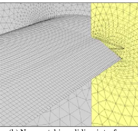
re-meshing or overset grids. The strategy used exploits an elastic analogy by assuming the grid is represented as an elastic continuum deformed through an external dedicated Finite-Element solver; this formulation does not require the introduction of torsional springs and rotational degrees of freedom for each node as proposed in [5], thus keeping computational costs very low. Details on the numerical implementation of the proposed procedure can be found in [6]. Special care must be taken in the treatment of the governing surface movements, such as the ailerons, rudder and the all movable stabilators. In fact, the surface rotation modifies the CFD domain topology by creating cuts and new wall surfaces in the boundary. As a result, the correct treatment of these conditions ideally requires the creation of a new mesh during the time simulation, significantly increasing the computational burden. To overcome this hurdle, a solution based on the application of the non-conformal mesh technique is used. This tecnique allows to define distinct domains associated with the movable surfaces which may be deformed independently from the rest of the grid, and exchange information with the others by means of an interpolation scheme across dedicated boundary surfaces. In this way it is possible to solve in a smart and efficient manner the surface movement, even when problems with large rotations are analyzed. Figure 2 shows the results of method applied for the case of large aileron control surface deflection.
(a) Surface block inside the master domain (b) Non-matching sliding interfaces
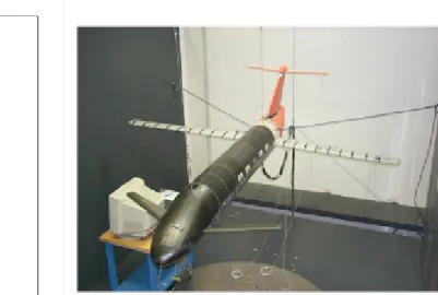
The CFD procedure is applied to the aeroelastic demonstrator named X-DIA [7] and shown in Figure 3. This demonstrator is a dynamically fully scaled wind tunnel model, designed and built at Politecnico di Milano, with the aim to evaluate by means of numerical and experimental activities, the beneficial effect of active controls coupled to a high number of control surfaces, in order to improve aircraft aeroelastic responses and efficiency. The wing under analysis, is forward swept with a sweep angle of -15° degs, and a dihedral angle of 6° degs. Respectively two inner and outer leading
(LEI and LEO) and trailing edge (TEI and TEO) control surfaces are installed at two different spanwise sections, resulting in four total control surfaces. The wing has been produced using a classical technique which employs a main spar to reproduce stiffness distribution along span and aerodynamic sectors, properly attached to this spar, to reproduce external shape and also mass and inertia distribution. Figure 4 shows the aeroelastic wing model in the wind-tunnel facility at the Dipartimento di Ingegneria Aerospaziale.
(a) CAD model of the initial project (b) X-DIA aeroelastic model
Fig. 3 – Overview of the X-DIA model
Figure 5 shows the overall dimensions of the computational domain around the main wing of the X-DIA experimental model. A symmetry boundary condition is imposed on the symmetry plane of the wing and a numerical far field boundary condition is used to impose the free-stream flow conditions. The mesh (which contains 219.786 nodes and 627.468 mixed cells) is ‘hybrid-type’ and unstructured with prismatic cells for boundary layer modeling and with external pyramids and tetrahedra. All turbulent flow is assumed in the computations; the one-equation model for turbulent viscosity proposed by Spalart and Allmaras is adopted, enhanced with wall function technique for the linear logarithmic law on the first layer of cells. Spatial discretization is based on MUSCL scheme and time discretisation on a first-order Backward Euler scheme (this is the only choice available when using the ALE formulation [8] in FLUENT© with moving grids).
Computations are carried out simulating the real experimental condition of the available wind tunnel; free stream Mach number M8 of
0.1 and Reynolds number Re8 of 4.6 105.
Figure 6 shows the aerodynamic transfer matrix coefficients related to respectively leading and trailing edge control surfaces compared to a classic potential method named Doublet Lattice Method (DLM) [9]. As expected, the leading edge control surface rigid mode leads to the main discrepancies between the two model aerodynamic models, where half of the hinge-line moment is predicted by the CFD model. Differences in pressure field prediction between DLM and RANS models, thickness and viscous effects are identified as the main causes of such differences. Good agreement is surprisingly found for the trailing edge control surface hinge moment. Further information regarding the application of control methods for the considered wing can be found in [10].
(a) Computational domain (b) Pathlines along deflected surfaces
Fig. 5 - a) Computational domain with boundary conditions and b) pathlines for inner leading and trailing control surfaces deflected respectiovely of 10° and 20° degs
(a) Mode 2 (b) Mode 4
Transonic Aeroelasticity
Complex aeroelastic phenomena may arise in the transonic speed range caused by shock waves that appear and move in the flow field as consequence of the flexible motions of the aircraft structure. The correct aeroelastic characterization can be carried out using Computational Fluid Dynamics (CFD) solvers for the evaluation of aerodynamic loads. Up to now the complexity of the procedures and the high amount of specialized computational resources required for the application of these models precludes them form being extensively used for industrial aeroelastic analyses. It opininion of the authors that it is nowadays possible to define strategies to solve transonic aeroelastic problems with CFD for industrial cases without adopting specialized pieces of software. Different classes of problems, all useful at different stages of the design, are here tackled for aeroelastic assessment of the
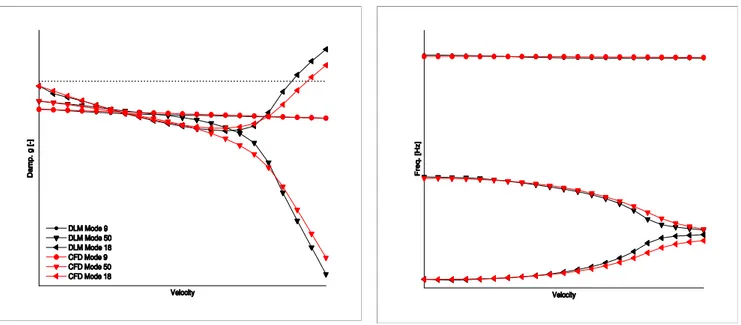
aircraft: a) computation of aeroelastic trim configuration for free aircraft in different flying conditions; b) computation of linearized generalized aerodynamic forces for fast and efficient assessment of flutter boundaries; c) verification of the computed flutter boundaries using time domain nonlinear coupled fluid and structural simulations. All these procedures are available are are being tested on the trainer M-346 by Alenia Aermacchi. Further information can be found in [11]. A comparison of the results obtained by the CA procedure with classical Doublet-Lattice Method (DLM) is here proposed to validate the developed method. The subsonic regime is studied to correctly use the DLM under its working-hypothesis, i.e no shock wave. Figure 7 show the V-f and V-g plots obtained using the two methods. In this case the two flutter velocity differ by less than 5%.
Fig. 7 – Damping (left) and frequency (right) trends at different flight velocities: comparison of the results obtained by CFD model and DLM at Match 0.6
Acknowledgements
The authors wish to acknowledge Sara Bozzini, Raffaele Ponzini and Paolo Ramieri of CILEA Consortium, for the technical suport on Avogadro computing cluster.
References
[1] G. Quaranta, P. Masarati, and P. Mantegaz-za, “A conservative mesh-free approach for fluid-structure interface problems,” in International Conference on Computational Methods for Coupled Problems in Science and Engineering (M. Papadrakakis, E. O˜nate, and B. Schrefler, eds.), (Santorini, Greece), CIMNE, 2005.
[2] J. P. Giesing, T. P. Kalman, and W. P. Rodden, “Correction factor tecniques for improving aerodynamic prediction methods,” CR 144967, NASA, 1976.
[3] J. Batina, “Unsteady Euler airfoil solution using unstructured dynamic meshes,” AIAA Journal, vol. 28, pp. 1381– 1388, 1990. [4] C. L. Bottasso and D. Detomi, “A procedure
for tetrahedral boundary layer mesh generation,” Engineering with Computers, vol. 18, pp. 66–79, April 2002.
[5] C. Degand and C. Farhat, “A three-dimensional torsional spring analogy method for unstructured dynamic meshes,” Computers and Structures, vol. 80, pp. 305– 316, 2002.
[6] L. Cavagna, G. Quaranta, and P. Mantegaz-za, “Application of Navier-Stokes simulations for aeroelastic stability assessment in transonic regime,” Computers & Structures, doi: 10.101.6/j.compstruc. 2007.01.005. [7] A. De Gaspari and L. Riccobene, “Progetto e
validazione di un modello di ala a freccia negativa con controllo attivo multi-superficie,” 2006. M.Eng. Thesis.
[8] J. Donea, “Arbitrary Lagrangian–Eulerian finite element methods,” in Computational Methods for Transient Analysis (T. Belytschko and T. J. Hughes, eds.), ch. 10, pp. 474–516, Amsterdam, The Netherlands: Elsevier Science Publisher, 1983.
[9] E. Albano and W. P. Rodden, “A doublet– lattice method for calculating the lift distributions on oscillating surfaces in subsonic flow,” AIAA Journal, vol. 7, no. 2, pp. 279–285, 1969.
[10] L. Cavagna, S. Ricci, and A. Scotti, “Active aeroelastic control over a four control surface wind tunnel wing model,” in International Forum on Aeroelasticity and Structural
Dynamics IFASD-2007, (Stochkolm, Sweden), June 18-20, 2007.
[11] L. Cavagna, G. Quaranta, P. Mantegazza, and D. Marchetti, “Aeroelastic assessment of the free flying aircraft in transonic regime,” in International Forum on Aeroelasticity and Structural Dynamics IFASD-2007, (Stochkolm, Sweden), June 18-20, 2007.
![Figure 6 shows the aerodynamic transfer matrix coefficients related to respectively leading and trailing edge control surfaces compared to a classic potential method named Doublet Lattice Method (DLM) [9]](https://thumb-eu.123doks.com/thumbv2/123dokorg/2828736.3856/5.892.75.779.807.1071/aerodynamic-transfer-coefficients-respectively-compared-potential-doublet-lattice.webp)