FACOLTÀ DI CHIMICA INDUSTRIALE
Dipartimento di Chimica Industriale e dei Materiali
H
2
PRODUCTION FROM STEAM
ETHANOL REFORMING (ESR)
Tesi di dottorato di ricerca in
CHIMICA INDUSTRIALE
(Settore CHIM/04)
Presentata da
Dr. Irene BERSANI
Relatore
Coordinatore
Dr. Francesco BASILE
Prof. Fabrizio CAVANI
Correlatori
Prof. Giuseppe FORNASARI
Prof. Angelo VACCARI
ciclo XXIII
ethanol reforming hydrotalcite
rhodium pressure
1
Introduction
12
Literature review
32.1
Global view of renewable energy
32.1.1 Global energetic scenario 3
2.1.2 Renewable Energy Sources (RES) 6
2.1.3 H2 12
2.2
H2 relevance and applications
142.2.1 Ammonia synthesis 15
2.2.2 Methanol synthesis 16
2.2.3 Fischer-Tropsch synthesis 18
2.2.4 Dimethyl Ether synthesis 21
2.2.5 Direct Reduction of iron ore (DRI) 23
2.2.6 Hydrodesulfurization 24
2.2.7 Hydrodenitrogenation 25
2.2.8 Fuel cells 26
2.3
H2 production
322.3.1 Steam reforming process (SR) 33
2.3.2 Water gas shift reaction (WGS) 44
2.3.3 Partial oxidation (POx) 48
2.3.4 Autothermal reforming (ATR) 50
2.3.5 Catalytic partial oxidation (CPO) 51
2.4
Bioethanol steam reforming
552.4.1 Thermodynamic considerations 55
2.4.2 Reaction mechanism 67
2.4.3 Catalysts 81
2.4.4 Process Considerations 86
3
Experimental
1073.1
Catalysts preparation
1073.1.1 Catalysts from hydrotalcite type precursors 107
3.1.2 Catalyst from CeZrO2 matrix 108
3.1.3 Foam catalysts 108
3.2
Catalysts characterization
1093.2.1 X-Ray diffraction (XRD) analysis 109
3.2.2 Surface area and porosimetry analysis 110
3.2.3 Temperature programmed reduction (TPR) and oxidation (TPO)
analysis 110
3.2.4 Scanning and Transmission Electron Microscopy analysis 111
3.2.5 Infrared (IR) spectroscopy analysis 111
3.2.6 Other analysis 112
3.3
Laboratory plant
1133.4
Preliminary/Blank tests
1194
Results and discussion
1234.1
Aim of work
1234.2
Thermal decomposition of ethanol
1254.2.1 Reactivity with INCOLOY 800HT reactor 125
4.2.2 Reactivity with quartz reactor 127
4.3
Choice of formulation
1304.3.1 Rh-Ni catalyst: study of operative parameters 130
4.3.2 Rh catalysts: effect of a second metal 139
4.3.3 Rh catalysts: effect of the matrix 157
4.4
Preparation of foams with hydrotalcite
190 4.4.1 Preparation of stable slurries in organic solvent 1904.4.2 Characterization of powder 191
4.5
Under pressure conditions
2034.5.1 Under P tests with pure EtOH 203
4.5.2 Under P tests with surfin EtOH 206
4.5.3 Foams tests and comparisons 207
4.5.4 Characterization of spent catalysts 210
1
1
I
I
n
n
t
t
r
r
o
o
d
d
u
u
c
c
t
t
i
i
o
o
n
n
The global energy landscape is constantly and rapidly evolving in response to advancing technologies, energy and environmental policies, and in recent years also to an economic crisis that emphasized widely different growth dynamics among different areas of the world. In the past decade, the prices of the key energy sources have also shown a high level of instability, often not justified by the dynamics of demand and supply fundamentals, but rather related to the speculative behaviour of financial markets (1). To meet the challenges of energy security and climate change as well as the growing energy needs of the developing world, a global energy technology revolution is essential.
Renewable energy has already been recognized as playing a key role for a global energy future, with a diversity of renewable energy sources which would vary geographically. In addition energy sources as sunlight, wind and falling water are generally considered renewable and therefore sustainable over the relatively long term. Wastes and biomass fuels are also usually viewed as sustainable energy. Biomass, wind and geothermal energy are commercially competitive and are making relatively fast progress (2).
The potential role of hydrogen in the world’s future energy system has been analysed in many assessments (3) and remains a topic of vigorous, ongoing debate (4). Hydrogen is a “building block” product of remarkable industrial interest and it is indicated as energy carrier of increasing relevance (5). Today, “hydrogen economy” is high on the political agenda and on the priorities of agencies funding research. Hydrogen is claimed to replace hydrocarbons and to provide a clean fuel with no carbon emissions for use in stationary and mobile applications as well. Fuel cells will play a key role for both applications.
Although hydrogen can be produced from a large variety of sources by using different methods, up to now the most extensively used process is the steam reforming of hydrocarbons. Biomass can be also used to produce H2 by thermochemical or
biological processes. Metabolic processing appears as an interesting alternative for the treatment of wastes while generating H2 as product. Some other approaches for
hydrogen production from water or other hydrogen-containing materials such as photodecomposition or thermochemical processes are also in development. Solar photodecomposition of water still has many technical hurdles remaining that suggest it is decades away from large scale, cost-effective implementation (6).
The conversion of hydrocarbons to hydrogen and syngas will play an important role in the 21st century ranging from large gas to liquid plants and hydrogen plants for
refineries to small units providing hydrogen for fuel cells. The choice of technology for manufacture of syngas depends on the scale of operation (7).
Among the liquid H2 sources, C2H5OH is a good candidate for several reasons: (i)
ethanol is renewable and is becoming increasingly available; (ii) it is easy to transport, biodegradable, and low in toxicity; (iii) it could be easily decomposed in the presence of water to generate a hydrogen-rich mixture; and (iv) it is free from catalyst poisons such as sulfur. Haryanto et al. observed that the ethanol conversion and H2 production varies greatly with the reaction conditions, the type of catalyst and the method of catalyst preparation (8). The challenge is, therefore, to develop catalysts exhibiting high stability and activity for ethanol steam reforming with high yields of hydrogen and resistance to coke formation at relatively low temperature.
2
2
L
L
i
i
t
t
e
e
r
r
a
a
t
t
u
u
r
r
e
e
r
r
e
e
v
v
i
i
e
e
w
w
2
2.
.1
1
Gl
G
lo
o
ba
b
al
l
v
vi
ie
ew
w
o
of
f
r
re
en
ne
ew
wa
ab
bl
le
e
e
en
ne
er
rg
g
y
y
2
2
.
.
1
1
.
.
1
1
G
G
l
l
o
o
b
b
a
a
l
l
e
e
n
n
e
e
r
r
g
g
e
e
t
t
i
i
c
c
s
s
c
c
e
e
n
n
a
a
r
r
i
i
o
o
It is not an exaggeration to say that the future of human prosperity hinges on finding a way of supplying the world’s growing energy needs in a way that does not irreparably harm the environment. Until recently, it looked as if we had plenty of time to meet that challenge. No longer. Surging oil and gas prices have drawn attention to the physical and political constraints on raising production - and the vital importance of affordable supplies to the world economy. And the latest scientific evidence suggests that the pace of climate change resulting from man-made emissions of greenhouse gases - the bulk of which come from burning fossil fuels - is faster than predicted. The urgent need for a veritable energy revolution, involving a wholesale global shift to low-carbon technologies, is now widely recognised (9).
Climate change, coupled with concerns about high oil and energy prices, is driving a global trend towards the increased use of renewable energy. Unlike fossil fuels which are rapidly being depleted, renewable energy sources such as sunlight and wind are naturally replenished and therefore sustainable. Indeed, it is the perceived notion of sustainability that is driving governments around the world to introduce legislation promoting the use of renewable energy (10).
Currently, only about 18% of the world’s energy demand is supplied from renewable energy sources (9). However, there is great potential to increase this contribution. Indeed, it has been estimated that the technical potential of renewable energy is more than 18 times that of current global primary energy demand (11). This estimate, however, does not allow for economic and environmental constraints and is therefore somewhat misleading. Owing to constraints, such as economic competitiveness, the potential that is likely to be realized in practice will be only a fraction of this value. Despite this estimate, the International Energy Agency (IEA), the U.S. Energy Information Administration (EIA) and British Petroleum (BP) previsions show that in the future the world will see an ever-increasing role of fossil energy sources (9) (12) (13). In its World Energy Outlook 2008, the IEA describes a reference scenario for global energy demand and supply for fossil, nuclear and renewable primary energy sources (9). The comparison of IEA data with them of EIA show very similar trends: crude oil continue to be the most important energy source , followed by coal and
natural gas. Nuclear and renewable energies will grow slightly, but the dominance of fossil fuels remains unchanged (Fig. 2.1).
Fig. 2.1 World primary energy demand by fuel a)EIA, b)IEA (9) (12).
At the same time, although the developed world has accounted for the majority of world energy use, the U.S. Energy Information Administration predicts that demand for energy will increase by 70% from 2007 to 2035 in the world due to substantial economic development with the concomitant increases in energy demand in terms of electricity and fuels (Fig. 2.2 and Fig. 2.3)(12) (13)(14). The most rapid growth in energy demand from 2007 to 2035 occurs in nations outside the Organization for Economic Cooperation and Development (non OECD nations). Current OECD member countries (as of March 2010) are the United States, Canada, Mexico, Austria, Belgium, Czech Republic, Denmark, Finland, France, Germany, Greece, Hungary, Iceland, Ireland, Italy, Luxembourg, the Netherlands, Norway, Poland, Portugal, Slovakia, Spain, Sweden, Switzerland, Turkey, the United Kingdom, Japan, South Korea, Australia, and New Zealand.
This increasing trend in demand of energy of non OECD countries it is due to the necessity to improve standards of living but also to the increase of population, in fact in non OECD nations population continues to increase (Fig. 2.3). At the global level, the most fundamental relationship in energy economics remains robust: more people with more income means that the production and consumption of energy will rise.
Fig. 2.2 World primary energy demand by region a)EIA, b)IEA (12) (14).
Q ua dr ill ion B tu M toe History Projections Oil Coal Gas Biomass Nuclear
Hydro Other renewables
Q ua dr ill ion B tu
Fig. 2.3 World incremental trends: population, energy and gross domestic products (GDP) (13).
Last World Energy Outlook 2010 predicts that differently from non OECD countries, OECD nations show a decline in the demand of oil and coal and an increase of investments in renewables sources. The use of renewable energy triples between 2008 and 2035, driven by the power sector where their share in electricity supply rises from 19% in 2008 to 32% in 2035 ( Fig. 2.4 and Fig. 2.5). Renewables are entering the mainstream, but long-term support is needed to boost their competitiveness(14).
Fig. 2.5 Renewable primary energy demand (14).
About 98% of carbon emissions result from fossil fuel combustion. Reducing use of fossil fuels would considerably reduce the amount of carbon dioxide produced, as well as reducing the levels of the pollutants. Indeed, much of the variation in cost estimates to control carbon emissions revolves around the availability and cost of carbon-free technologies and carbon-reducing technologies, such as energy efficiency and energy conservation equipment. This can be achieved by either using less energy altogether, or using alternative energy resources. Much of the current effort to control such emissions focuses on advancing technologies that emit less carbon or no carbon such as nuclear, hydrogen, solar, wind, geothermal or on using energy more efficiently, and on developing innovative technologies and strategies to capture and dispose of carbon dioxide emitted during fossil fuel combustion.
2
2
.
.
1
1
.
.
2
2
R
R
e
e
n
n
e
e
w
w
a
a
b
b
l
l
e
e
E
E
n
n
e
e
r
r
g
g
y
y
S
S
o
o
u
u
r
r
c
c
e
e
s
s
(
(
R
R
E
E
S
S
)
)
Renewable energy has already been recognized as playing a key role for a global energy future, with a diversity of renewable energy sources which would vary geographically. In addition energy sources as sunlight, wind and falling water are generally considered renewable and therefore sustainable over the relatively long term. Wastes and biomass fuels are also usually viewed as sustainable energy. Biomass, wind and geothermal energy are commercially competitive and are making relatively fast progress (2).
Fig. 2.6 Main renewable energy sources and their usage form (2).
Hydropower, geothermal, solar and wind can be a useful substitute for power and heating generation, while biomass and biofuels, derived from biomass, appear to be an attractive option respect fossil fuels, in particular if it is considered that oil reserve will be finish in a brief period.
Biomass is an interesting alternative for three main reasons. First, it is a renewable resource that could be sustainably developed in the future. Second, it appears to have formidably positive environmental properties resulting in no net releases of carbon dioxide (CO2) and very low sulfur content. Third, it appears to have significant economic potential provided that fossil fuel prices increase in the future (15).
Mainly advantages of bio-fuels are the following: (a) bio-fuels are easily available from common biomass sources; (b) they are represent a CO2 cycle in combustion; (c) bio-fuels have a considerable environmentally friendly potential; (d) there are many benefits the environment, economy and consumers in using bio-fuels; and (e) they are biodegradable and contribute to sustainability (16).
2
2..11..22..11 BBiioommaassss
Biomass resources can be divided into two broad categories: natural and derived materials. Biomass resources include wood and wood wastes, agricultural crops and their waste by-products, municipal solid waste, animal wastes, waste from food processing and aquatic plants and algae. Biomass resource can be subdivided into three categories (17) (18):
Wastes. Agricultural production wastes, agricultural processing wastes, crop residues, mill wood wastes, urban wood-wastes, urban organic wastes.
Forest products. Wood, logging residues, trees, shrubs and wood residues, sawdust, bark, etc., from forest clearings.
Energy crops. Short rotation woody crops, herbaceous woody crops, grasses, starch crops (corn, wheat and barley), sugar crops (cane and beet), oilseed crops (soya bean, sunflower, safflower).
The components of biomass include cellulose, hemicelluloses, lignin, extractives, lipids, proteins, simple sugars, starches, water, HC, ash, and other compounds. Two larger carbohydrate categories that have significant value are cellulose and hemi-cellulose. The lignin fraction consists of non-sugar type molecules (19).Industrial biomass can be grown from numerous types of plants, including miscanthus, switchgrass, hemp, corn, poplar, willow, sorghum, sugarcane, (20)and a variety of tree species, ranging from eucalyptus to oil palm.
There are three ways to use biomass. It can be burned to produce heat and electricity, changed to gas-like fuels such as methane, hydrogen and carbon monoxide or changed to a liquid fuel. When biomass is used directly in an energy application without chemical processing then it is combusted. Conversion may be effected by thermochemical, biological or chemical processes. These may be categorized as follows: direct combustion, pyrolysis, gasification, liquefaction, supercritic fluid extraction, anaerobic digestion, fermentation, acid hydrolysis, enzyme hydrolysis, and esterification (21).
Fig. 2.7 Main biomass conversion processes (21). 2
2..11..22..11..11 PPyyrroollyyssiiss
It is thermo-chemical conversion process and is found to be best suited for conversion of biomass to liquid fuel. Pyrolysis is thermal destruction of biomass in the absence of air/ oxygen. Pyrolysis of biomass starts at 350-550 °C and goes up to 700 °C. This leads to the production of useful liquid oil, gases and solid products. Different condition leads to formation of products in different proportions (22). The physical conditions of the pyrolysis of biomass, such as temperature, heating rate and residence time have been shown to have a profound effect on the product yields and composition.
Slow pyrolysis. Biomass is pyrolysed at slow heating rates (5-7 °C/min). This leads to
Fast pyrolysis. Initially pyrolysis was done with slow heating rates. This in turn
produces more of char. The higher yield of desirable liquid product can be obtained by fast pyrolysis. It involves rapid heating of biomass but not as fast as flash pyrolysis. Heating rate is somewhere about 300 °C/min. Generally, fast pyrolysis is used to obtain high-grade bio oil. Fast pyrolysis is successful with most of fluidized bed reactors as it offers high heating rates, rapid de-volatilization, easy control, easy product collection, etc. (23).
Flash pyrolysis. Flash pyrolysis is the process in which the reaction time is of only
several seconds or even less. The heating rate is very high. This requires special reactor configuration in which biomass residence times are only of few seconds. Two of appropriate designs are entrained flow reactor and the fluidized bed reactor. Flash pyrolysis of any kind of biomass requires rapid heating and therefore the particle size should be fairly small (24).
2
2..11..22..11..22 CCoommbbuussttiioonn
The biomass is directly burnt in the presence of air to convert chemical energy stored in biomass into heat, mechanical power, or electricity, etc. It is possible to burn any type of biomass but in practice combustion is feasible only for biomass with moisture content of <50%. Combustion process has got many disadvantages. Biomass rarely arises naturally in an acceptable form of burning. In most of the cases it requires some pretreatment like drying, chopping, grinding, etc., which in turn is associated with financial costs and energy expenditure (25) (26).
2
2..11..22..11..33 GGaassiiffiiccaattiioonn
Gasification is a form of pyrolysis, carried out at high temperatures (800-900 °C) in order to optimize the gas production. The resulting gas, known as producer gas, is a mixture of carbon monoxide, hydrogen and methane, together with carbon dioxide and nitrogen. The gas is more versatile than the original solid biomass (usually wood or charcoal): it can be burnt to produce process heat and steam, or used in gas turbines to produce electricity (19).
2
2..11..22..22 BBiiooffuueellss
Biofuel is a renewable energy source produced from natural (biobased) materials, which can be used as a substitute for petroleum fuels. The term biofuel is referred to as solid (bio-char), liquid (ethanol, vegetable oil and biodiesel) or gaseous (biogas, biosyngas and biohydrogen) fuels that are predominantly produced from biomass. The most common biofuels, such as ethanol from corn, wheat or sugar beet and biodiesel from oil seeds (rape in particular), are produced from classic food crops that require high-quality agricultural land for growth. It is assumed that biodiesel is used as a petroleum diesel replacement and that ethanol is used as a gasoline replacement (27).
Fig. 2.8 Resources of main liquid biofuels for automotives (21).
Ethanol can be used directly in cars designed to run on pure ethanol or blended with gasoline to make ‘‘gasohol”. Anhydrous ethanol is required for blending with gasoline. No engine modification is typically needed to use the blend. Ethanol can be used as an octane- boosting, pollution-reducing additive in unleaded gasoline.
Most ethanol is currently being produced from sugar cane or corn. Yeast is used to ferment sugars into ethanol. In the case of carbohydrates (such as corn), a pretreatment step of converting carbohydrate into sugars is needed. Currently, the corn ethanol industry uses either a dry-milling or a wet-milling process. Upon fermentation, ethanol content is only about 10%, which requires a significant effort in separation to produce the pure ethanol needed for fuel use. Distillation can concentrate ethanol to just below the azeotropic concentration (95 mol%), after that, specialized separations (molecular sieve, azeotropic distillation, lime drying) are needed.
World production of ethanol from sugar cane, maize and sugar beet increased from less than 20 billion liters in 2000 to over 40 billion liters in 2005. This represents around 3% of global gasoline use. Production is forecasted to almost double again by 2010 (28).
Biodiesel is a synthetic diesel-like fuel produced from vegetable oils, animal fats or waste cooking oil. It can be used directly as fuel, which requires some engine modifications, or blended with petroleum diesel and used in diesel engines with few or no modifications. At present, biodiesel accounts for less than 0.2% of the diesel consumed for
Fig. 2.9 World production of ethanol and biodiesel, 1980–2007 (22).
transport(28). Biodiesel has become more attractive recently because of its environmental benefits.
The cost of biodiesel, however, is the main obstacle to commercialization of the product. With cooking oils used as raw material, the viability of a continuous transesterification process and recovery of high quality glycerol as a biodiesel by-product are primary options to be considered to lower the cost of biodiesel (29) (30). The oil in the vegetable seeds is converted into biodiesel through oil extraction, oil refining, and transesterification. The cost of biodiesel can be lowered by increasing feedstock yields, developing novel technologies, and increasing economic return on glycerol production by finding other uses for this by-product, which, at the moment, due to oversupply is sold for little or no value.
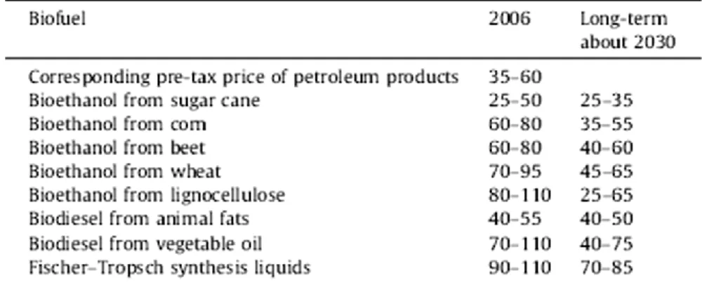
Biofuels production costs can vary widely by feedstock, conversion process, scale of production and region. On an energy basis, ethanol is currently more expensive to produce than gasoline in all regions considered. Only ethanol produced in Brazil comes close to competing with gasoline. Ethanol produced from corn in the US is considerably more expensive than from sugar cane in Brazil, and ethanol from grain and sugar beet in Europe is even more expensive (Fig. 2.10). These differences reflect many factors, such as scale, process efficiency, feedstock costs, capital and labor costs, co-product accounting, and the nature of the estimates(31).
Fig. 2.10 Estimated costs of biofuels compared with the price of oil (biofuels exclusive of taxes),(US cents/liter)(31).
For biofuels, the cost of feedstock (crops) is a major component of overall costs. Total biofuel costs should also include a component representing the impact of biofuels production on related markets, such as food. In particular, the cost of producing oil-seed-derived biodiesel is dominated by the cost of the oil and by competition from high-value uses like cooking (Fig. 2.10).
Trying to avoid competition with food a second generation of biofuels was taken in exam for transport field. In general, second generation biofuels are produced from cellulosic materials (lignocellulosic feedstocks). These raw material options may result in the production of more fuel per unit of agricultural land used and require less
chemical and energy input per production and harvesting resulting in a higher yield. Such raw materials may be considered more sustainable and do not compete directly with food. However, there can be competition for land use as well as competition between the potential use of cellulosic materials for liquid biofuels and current use for heat and power generation through combustion as solid biofuels.
At this point biofuels can be classified based on their production technologies: first-generation biofuels; second first-generation biofuels; third first-generation biofuels; and fourth generation biofuels. Classification of biofuels based on their generation technologies is shown in Fig. 2.11. The first-generation biofuels appear unsustainable because of the potential stress that their production places on food commodities. Second generation biofuels need to build on the need for sustainable liquid fuels through processing including pyrolysis and hydrothermal liquefaction (31).
Fig. 2.11 Classification of biofuels based on their generation technologies(31).
Also for bioethanol, with the current trend in ethanol use (Fig. 2.9), demand is likely to increase significantly in the near future and starch or sugar-based ethanol production has been blamed for the rise in the food prices. To satisfy current and future demands, ethanol production from lignocellulosic biomass fermentation is a viable option that does not compete with the food supply.
2
2
.
.
1
1
.
.
3
3
H
H
2
2
The potential role of hydrogen in the world’s future energy system has been analysed in many assessments (3) and remains a topic of vigorous, ongoing debate (4).
Hydrogen is a “building block” product of remarkable industrial interest and it is indicated as energy carrier of increasing relevance (5). Hydrogen is found naturally in hydrogen-rich compounds; it cannot be extracted like natural gas or oil, but needs to be released by applying energy. On the one hand, this represents a drawback because the process requires the input of primary energy carriers like coal, natural gas or biomass, of electricity or high temperatures.
The advantage is that a wide range of different feedstocks and energy sources can be used for hydrogen production, in particular from fossil fuels, biofuels by thermochemical way and from water by electrolytic way (32).
The interest on hydrogen-based energy systems surged in response to the first oil crisis and the growing concerns about environmental issues. The advantages are the hydrogen nearly zero emissions, its potential role in reducing greenhouse gases (improving air quality), reducing climate changes and the possibility of local production on the basis of a variety of fuels (decreasing dependence on imported oil). In fact, the high end-use efficiency in fuel cells and the possibility to produce hydrogen from non-fossil sources or clean non-fossil fuels (non-fossil fuel combustion in combination with coke capture and storage - CCS) could reduce greenhouse gas emissions from the energy system(33).
Today, “hydrogen economy” is high on the political agenda and on the priorities of agencies funding research. Hydrogen is claimed to replace hydrocarbons and to provide a clean fuel with no carbon emissions for use in stationary and mobile applications as well. Fuel cells will play a key role for both applications.
Fig. 2.12 Energy sources for hydrogen production and possible applications (30).
2
2.
.2
2
H2
H
2
r
re
el
le
ev
va
an
nc
ce
e
a
an
nd
d
a
ap
pp
p
li
l
ic
ca
at
ti
io
on
ns
s
The development of hydrogen production technologies requires identification of potential markets and the constraints associated with those markets.
For non-carbon-dioxide-emitting hydrogen production technologies (nuclear, renewable, and fossil fuels with carbon dioxide sequestration), restrictions on carbon dioxide emissions to the atmosphere are an important factor in the increasing potential size of a future markets(34). Existing and potential hydrogen markets were identified as follows(34):
Industrial. The two major industrial markets for hydrogen are fertilizer production as ammonia, steel, methanol and H2 for cracking and hydrodesulphurization. All nitrate fertilizers require hydrogen in their production processes. Some but not all steel production processes require hydrogen. These are large-scale facilities that match large-scale hydrogen production systems.
Vehicle. Transportation requirements can be met with different fuels (methanol, dimethyl ether, Fischer-Tropsch fuels or gasoline, diesel, jet fuel and in the future H2 itself). Each fuel requires different amounts of hydrogen in the production process and has different economics of scale.
Power. Hydrogen is a candidate for power production, particularly as a vector for storage and use for production when necessary.
Commercial. Hydrogen is being considered for commercial applications in buildings with the co-generation of power and heat.
With interest in its practical applications dating back almost 200 years, hydrogen energy use is hardly a novel idea. What is new is the confluence of factors since the mid-1990s that increase the attractiveness of hydrogen energy economy. Those factors include persistent urban air pollution, demand for low or zero-emission vehicles, the need to reduce foreign oil imports, carbon dioxide emissions and global climate change, and the need to store renewable electricity supplies. These considerations are not confined to a single nation or region, and make hydrogen a virtually ideal energy carrier that is abundantly and equitably available to humanity (35).
2
2
.
.
2
2
.
.
1
1
A
A
m
m
m
m
o
o
n
n
i
i
a
a
s
s
y
y
n
n
t
t
h
h
e
e
s
s
i
i
s
s
Ammonia is used in various applications, such as textile processing, water purification, and manufacturing explosives. The main part, however, is used as fertilizer(36). Ammonia production consumes about half of the hydrogen produced today and it is the primary chemical industry utilization of hydrogen. Ammonia is currently made where there is inexpensive natural gas that provides economical hydrogen and shipped to the costumer. The low cost of shipping ammonia favors very large ammonia production plants with very large demands for hydrogen (34).
At the beginning of the 20th century, the use of nitrogenous fertilizers was already well established. Haber and Bosch developed the direct synthesis of ammonia from hydrogen and nitrogen (37).
The synthesis of ammonia from nitrogen and hydrogen is a clean reaction, in that it is not complicated by the formation of byproducts, such as hydrazine, and the thermodynamics are seemingly straightforward.
ΔH°700K = - 52.5 kJ/mol
1/2 N2 + 3/2 H2 NH3 ΔG°700K = + 27.4 kJ/mol
ΔS°700K = + 288 J/molK
The reaction is exothermic and is accompanied by a decrease in volume at constant pressure. The value of the equilibrium constant (Kp) therefore increases as the temperature is lowered, and the equilibrium ammonia concentration increases with increasing pressure.
The formation of ammonia is favoured by operation at high pressure and low temperature. The optimum pressure for economic operation with the available catalysts has been in the range 150 - 350 bar. Normally, the advantages of the higher equilibrium concentration of ammonia at very high pressure are more than offset by the higher costs of both gas compression and additional plant capital.
The temperature at which the synthesis process is operated is determined by the activity characteristics of the catalyst. Thermodynamically, low temperature is advantageous, but for kinetic reasons high temperatures have to be used. The most effective catalyst is clearly the one that will give the highest rate of conversion of ammonia at the lowest temperature.
As the synthesis reaction proceeds, the heat of reaction causes the temperature to rise down the bed, so making the specific rate of reaction faster. Since the equilibrium becomes less favourable at higher temperatures, the rate of the reverse reaction is progressively increased and the overall conversion becomes equilibrium-controlled. Careful control of the temperature profile is therefore necessary for the equilibrium balance to be obtained between the limit set by the thermodynamic equilibria, and by
the kinetics of the catalyzed reactions in both forward (synthesis) and reverse (ammonia decomposition) directions.
The main role of the ammonia catalyst is to dissociate the N2 bond. Under industrial
conditions, this is the rate-determining step (RDS) for NH3 synthesis on Ru, due to the
high bond energy. The dissociation takes place at defects and steps, rendering the NH3 synthesis extremely structure sensitive(36).
All commercial ammonia synthesis catalysts are currently based on metallic iron promoted with alkali (K), and various metal oxides, such as those of aluminium, calcium or magnesium. The principal material used to make these catalysts is usually magnetite (Fe3O4), with some of the components in the catalyst originating as
impurities in the magnetite. A typical catalyst contains approximately 0,8 % K2O, 2.0
% CaO, 0.3 % MgO, 2.5 % Al2O3 and 0.4 % SiO2, as well as traces of TiO2, ZrO2 and
V2O5. In developing the process to manufacture catalysts of this sort, it was
recognized that these minor components could have a large effect on the performance of the final catalyst, since they may also interact with each other, giving rise to both harmful and beneficial effects. In modern catalysts, these factors have been taken onto account, resulting in optimized performance in terms of high activity and long life.
2
2
.
.
2
2
.
.
2
2
M
M
e
e
t
t
h
h
a
a
n
n
o
o
l
l
s
s
y
y
n
n
t
t
h
h
e
e
s
s
i
i
s
s
Methanol is inside the top 10 produced molecules. Methanol has been a common chemical feedstock for several important chemicals such as acetic acid, methyl ter-butyl ether (MTBE), formaldehyde and chloromethane. Moreover, methanol being a clean liquid fuel could provide convenient storage of energy for fuel cell applications, particularly in transportation and mobile devices(38). In additions, over the last few decades, hydrocarbons (MTHC) technologies, in particular methanol-to-olefin (MTO) and methanol-to-gasoline (MTG), have been the focus for a large number of researcher dealing with the upgrading of natural resources beneficial both for the petrolchemistry and fuel industries (39) (40)(41).
The process to synthesize methanol from carbon monoxide and hydrogen was introduced by BASF in 1923 and it was the second large-scale application of catalysis (after ammonia synthesis) and high-pressure technology (100-300 bar) to the chemical industry (37).
Like the ammonia process, methanol synthesis was dependent on the development of an effective catalyst, but unlike the ammonia synthesis catalyst, the methanol catalyst had to be selective as well as active.
The reactions involved in the methanol synthesis are:
ΔG°298K = - 25.3 kJ/mol
(B) CO2 + 3 H2 CH3OH + H2O ΔH°298K = - 49.5 kJ/mol
ΔG°298K = + 3.3 kJ/mol
(C) CO + H2O CO2 + H2 ΔH°298K = - 41.2 kJ/mol
ΔG°298K = - 28.6 kJ/mol
Reaction (B) and (C) combined are equivalent to reaction (A), so that either, or both, of the carbon oxides can be the starting point for methanol synthesis.
Reactions (A) - (C) are exothermic; reactions (A) and (B) are accompanied by a decrease in volume. Hence, the value of the equilibrium constant decreases with temperature and increases with pressure (Kp = pCH3OH / pCOp2H2). Thus, high
conversions to methanol, given a sufficiently active catalyst, will be obtained at high pressures and low temperatures.
In addition to the synthesis of methanol, both carbon monoxide and carbon dioxide can take part in other hydrogenation reactions, producing by-products such as hydrocarbons, ethers and higher alcohols:
(D) CO + 3 H2 CH4 + H2O ΔH°298K = - 206.2 kJ/mol
ΔG°298K = - 142.2 kJ/mol
(E) 2 CO + 4 H2 CH3OCH3 + H2O ΔH°298K = - 204.8 kJ/mol
ΔG°298K = - 67.2 kJ/mol
(F) 2 CO + 4 H2 C2H5OH + H2O ΔH°298K = - 255.6 kJ/mol
ΔG°298K = - 122.6 kJ/mol
These reactions are much more exothermic than the methanol synthesis reactions and methanol is thermodynamically less stable and less likely to be formed from carbon monoxide and hydrogen than the other possible products, such as methane. Which of the products is formed is controlled by kinetics factors; that is, by the catalyst being selective in favouring a reaction path leading to the desired product. The catalytic synthesis of methanol from syngas has been conventionally carried out in two-phase reactors with the syngas and products in the vapour phase and the catalyst as solid phase. The large exothermic heat of reaction in addition to the low heat capacity of the vapour increases the potential for thermal runaway and damage to the catalyst in the vapour phase, thus limiting the maximum operable reaction temperature(42).
There are two class of catalysts studied and used for methanol synthesis: high-pressure and low-high-pressure catalysts (Tab. 2.1). The difference in preparation methods, synthesis conditions, and pre-treatment have a considerable influence on the
structure of the catalysts, which finally leads to disparities in the catalytic performance. It is generally accepted that a large specific Cu surface area leads to an active methanol synthesis catalyst. In addition, the metal-support interaction plays a key role in this catalytic reaction (43).
Tab. 2.1 Catalysts proposed or used for industrial methanol synthesis (37).
2
2
.
.
2
2
.
.
3
3
F
F
i
i
s
s
c
c
h
h
e
e
r
r
-
-
T
T
r
r
o
o
p
p
s
s
c
c
h
h
s
s
y
y
n
n
t
t
h
h
e
e
s
s
i
i
s
s
The growing reliance on imported oil gave the synthetic fuels a fresh impetus in the 1980s (44)(45). The Fischer-Tropsch synthesis (FTS) is the exothermic reaction of carbon monoxide and hydrogen to mainly hydrocarbons together with water and carbon dioxide. It can be represented by the following reaction equation:
n CO + (2n +1) H2 CnH2n+2 + n H2O
Sabatier was the first to react carbon monoxide and hydrogen over a nickel catalyst in 1902. The result was the production of methane and water. Then, in 1923 Franz Fischer and Hans Tropsch of the Kaiser Wilhelm Institute (Germany) developed the Fischer-Tropsch process (i.e. Synthol process), in which a carbon monoxide and hydrogen flow, in the presence of iron, cobalt or nickel catalyst at 180-250 °C and at pressures from atmospheric to 150 bar, produced a mixture of straight hydrocarbons and smaller amounts of oxygenates. The initial objective of this process was gasoline production. Experience at high and medium reactor pressures was disappointing from an unacceptably high oxygenate product content point of view. Hence, it was adopted
Catalyst composition
Active phase in
methanol synthesis Properties and use
ZnO ZnO Original synthesis catalyst, short life
ZnO/Cr2O3
(ICI catalyst) ZnO Standard high pressure catalyst
ZnO/MnO/Cr2O3 +
alkali
Alkalized ZnO (+MnO)
Standard high pressure catalyst for methanol and higher alcohol mixtures Cu/ZnO
Cu/ZnO/Cr2O3
Cu Early low pressure catalysts, short life Cu/ZnO/Al2O3
(ICI catalyst) Cu Industrial low-pressure catalyst
Pd/SiO2
Pd/basic oxides Pd
Active; poorer selectivity than copper catalysts (by-products: hydrocarbons) Rh/SiO2
Rh/basic oxides Rh
Active; poorer selectivity than copper catalysts (by-products: hydrocarbons)
Rh complex Rh complex
Low activity; poorer selectivity (homogeneous catalyst; co-product: ethylene glycol)
an atmospheric reactor pressure. Cobalt became strongly favoured as catalytic element, since iron was less active and deactivated rapidly at atmospheric pressure synthesis operation, while nickel gave high methane selectivity and was affected by its loss due to volatile nickel tetracarbonyls production (46) (47).
The best catalyst was found to be based on cobalt, supported on Kieselguhr with thoria and magnesium oxide as promoters (100g Co / 5g ThO / 8g MgO / 200g Kieselguhr).
In recent years, we assist to a second renewal of interest in the F-T process for producing liquid hydrocarbons. This new interest centres on making synthetic fuels from natural gas instead of coal.
The process of converting natural gas or coal into marketable liquid hydrocarbons comprises three main elements: 1) synthesis gas production, 2) hydrocarbon synthesis via the F-T conversion process, 3) products work-up.
As far as syngas production is concerned, other feedstocks such as coal, heavy residue or shale oil can be used, but the process becomes less economical.
Sasol is the largest producer of synfuels and chemicals made by coal gasification (Lurgi’s technology is employed). Besides coal plants, since 1993 Sasol has also operated natural gas-based plants at Mossgas, South Africa, with a capacity of 44.000 BPD of fuels. The company is by far the most experienced player in the syngas-based chemical business, as far as reactors design, catalytic formulations, process technology are concerned.
Sasol has been opting for iron-based catalyst since 1955. Only in recent years the advantages of cobalt based catalyst for use in slurry phase reactor have been recognized.
For the preparation of Synthol catalyst, Sasol uses iron oxides: the suitable iron oxide is fused together with the required chemical and structural promoters. The fused ingots are milled to a specified particle size range (for optimum fluidization properties). The catalyst is pre-reduced with H2 at about 400 °C and then loaded in the F-T reactors. Because of the simplicity of the preparation and the low cost of the row materials, the cost of Synthol catalyst is a minor part of the overall process (48). Studies performed at Sasol on the commercial spray dried precipitated iron catalyst and Co/Al2O3 slurry phase FTS catalyst, resulted in the following conclusions:
1. the cobalt does not show any significant water-gas-shift activity and no water inhibition of the F-T reaction rate,
2. the cobalt catalyst is the preferred option if high per pass conversions are required,
3. desired stabilized intrinsic activity levels can be achieved with cobalt catalyst, implying that extended slurry phase synthesis runs can be realized,
4. cobalt derived hydrocarbon product selectivities show greater sensitivity towards process conditions (i.e. reactor pressure) than that of iron. Iron catalyst, on the other hand, shows marked sensitivity towards chemical promotion. Indeed, the geometric tailoring of pre-shaped support materials can be an optimization tool for effecting increased wax selectivities with cobalt based catalyst, an approach also suggested by others (Exxon, Shell).
The conversion of synthesis gas to hydrocarbons (Fischer-Tropsch synthesis) has been widely studied and extensively described. A number of synthesis reactions can occur and the whole are quite exothermic, ΔH = -170 kJ (C/atom):
Methanation: CO + 3 H2 CH4 + H2O
Paraffins: n CO + (2n + 1) H2 CnH2n+2 + n H2O
Olefins: n CO + 2n H2 CnH2n + n H2O
Alcohols: n CO + 2n H2 CnH2n+1OH + (n-1) H2O
Some other reactions, such as the water-gas shift or Boudouard reaction also occur:
WGS: CO + H2O CO2 + H2
Boudouard: 2 CO C(s) + CO2
The free energy changes (ΔG°) in the above reactions are such that the hydrocarbon synthesis is normally favoured below about 400 °C. Over the temperature range of 200-400 °C, the formation of methane is favoured. However, since the thermodynamic equilibrium is reached slowly in FT synthesis, it is possible to take advantage of kinetic factors by using suitable catalysts, so that heavier hydrocarbons or alcohols are produced in suitable quantity(45).
The production of hydrocarbons using traditional FT catalysts, such as Fe or Co, is governed by chain growth or polymerization kinetics. The so-called “surface carbide” mechanism is a plausible one for the interaction of CO and H2 with the catalytic
surface and the subsequent synthesis of hydrocarbons. Ample evidence shows that this is the prevalent mode of activation of CO at elevated temperatures on the Group VIII metal catalysts Fe, Co, Ni and Ru (44)(45). The model can be used as a starting point for understanding the formation of various molecular species during FT synthesis and also for examining hydrocarbon chain growth(45).
The nature of the product and the product distribution among the carbon numbers will depend upon the catalyst surface, composition (H2/CO ratio) and the rate of flow
feed gas, reaction pressure and the temperature at which FT synthesis is performed. The above parameters will affect the rate of hydrogen and CO dissociation, hydrogenation, degree of polymerization and desorption of the product species(45).
At low temperatures, the main primary products are linear 1-alkenes, alkanes, alcohols and aldehydes. The linearity of the product is important for many of their applications. It gives the waxes with high melting point and low viscosity.
The C9 to C15 olefins are ideal for the manufacture of biodegradable detergents. The
C10 to C18 cut is an excellent diesel fuel (with the high cetane number of 75 and zero
aromatics). On the other hand, the product linearity is a disadvantage for gasoline production, since a high octane number requires branched alkane and aromatics. Hence, the gasoline requires extensive isomerisation and aromatization.
At higher synthesis temperatures secondary reactions occur, i.e branched hydrocarbons and aromatics are formed. In that way, the diesel cetane number decreases, while the gasoline octane number increases. Olefins in the hydrocarbons reach a maximum at C3 or C4 (up to 90 %), to then decrease continuously, the waxes
being essentially paraffinic (47).
2
2
.
.
2
2
.
.
4
4
D
D
i
i
m
m
e
e
t
t
h
h
y
y
l
l
E
E
t
t
h
h
e
e
r
r
s
s
y
y
n
n
t
t
h
h
e
e
s
s
i
i
s
s
Dimethyl ether (DME) is an alternative fuel that could potentially replace petroleum-based fuels(49). Dimethyl ether is the simplest ether (CH3OCH3). The physical
properties of DME are similar to those of liquefied petroleum gases (propane and butane). It burns with a visible blue flame and is non-peroxide forming in the pure state or in aerosol formulations. Unlike methane, DME does not require an odorant because it has a sweet ether-like odour. It is a volatile organic compound, but is non-carcinogenic, non-teratogenic, non-mutagenic and non-toxic(49).
Currently, the major usage of DME is as a propellant in the aerosols industry. In addition, it can be used as a clean-burning fuel in diesel engines, as a household fuel (LPG alternative) for heating and cooking, as a fuel for gas and turbines in power generation, as a fuel for fuel cells, and as a chemical feedstock for higher ethers and oxygenates (42)(50).
Traditionally, DME has been produced in a two steps process where syngas is first converted to methanol, followed by methanol dehydration to dimethyl ether.
CO + 2 H2 CH3OH ΔH°298K = - 90.6 kJ/mol
CH3OH CH3OCH3 + H2O ΔH°298K = + 23.4 kJ/mol
H2O + CO H2 + CO2 ΔH°298K = - 41.2 kJ/mol
3 CO + 3 H2 CH3OCH3 + CO2 ΔH°298K = + 258.6 kJ/mol
Natural gas is not the only resource that can be used to generate syngas, coal and biomass can also be used. Hence, DME production is not limited to one feedstock and the price of DME synthesis process is directly related to the price of the feedstock. New processes are being commercialized to produce DME in a single step via autothermal reactors and slurry phase reactors.
DME can be introduced and exploited with existing technologies, and enable the eventual implementation of advanced technologies, such as fuel cells. Because DME is produced from natural gas, coal or biomass, it can increase the energy security by displacing petroleum derived fuels.
The prominent advantages of DME as a fuel and energy carrier are(49):
1. DME, due to its high cetane number(51), can be used in the most efficient engine technology currently produced. DME demonstrated lower NOx and SOx than
conventional diesel, is sootless (52).
2. Using exiting engine technology, DME produces the least amount of well-to-wheel greenhouse gas emissions compared to FT diesel, FT naphtha, diesel, bio-naphtha, methanol, methane and ethanol.
3. Excluding natural gas, DME has the highest well-to-wheel efficiency of all non-petroleum based fuels using conventional, hybrid and fuel processor fuel cell vehicle technologies.
4. DME can be used as a residential fuel for heating and cooking.
5. On-board automotive fuel processors using methanol and DME exhibit the lowest start-up energies and the lowest fuel processor volumes - correlating to higher overall efficiencies as compared to ethanol, methane and gasoline fuel processor fuel cell vehicles.
6. The infrastructure of DME is less cost intensive than that for hydrogen because DME can use the existing LPG and natural gas infrastructures for transport and storage.
Synthesis of DME from syngas in a single step is more favourable in thermodynamic and economical (50)(51).
Single-stage DME synthesis in the vapour phase suffers from low per pass conversions(44), due, in part, by the effects of high temperature on the catalysts. Gas-phase DME synthesis processes, in general, suffer from the drawbacks of low hydrogen and CO conversions per pass, along with low yield and selectivity of DME, coupled with a high yield of carbon dioxide. These processes are typically expensive due to high capital costs for reactors and heat exchangers, and high operating costs
due to inefficient CO utilization and high recycle rates. Using an inert liquid as a heat sink for highly exothermic reactions offers a number opportunities in syngas processing. Heat generated by the exothermic reactions is readily accommodated by the inert liquid medium. This enables the reaction to be run isothermally; minimizing catalyst deactivation commonly associated with the more adiabatic gas phase technologies(42).
The process is based on dual-catalytic synthesis in a single reactor stage, and based on a combination of an equilibrium limited reaction (methanol synthesis) and an equilibrium unlimited reaction (methanol dehydration). The methanol synthesis and the water gas shift reaction take place over the co-precipitated Cu/Zn/Al2O3 catalyst and the methanol dehydration takes place over γ- Al2O3 or zeolites catalysts (50)(51)(52). Moreover, by varying the mass ratios of methanol synthesis catalyst, it is possible to co-produce DME and methanol in any fixed proportion, from 5 % DME to 95 % DME(42).
2
2
.
.
2
2
.
.
5
5
D
D
i
i
r
r
e
e
c
c
t
t
R
R
e
e
d
d
u
u
c
c
t
t
i
i
o
o
n
n
o
o
f
f
i
i
r
r
o
o
n
n
o
o
r
r
e
e
(
(
D
D
R
R
I
I
)
)
Direct reduction of iron ore is today's major process for generating metallic iron, necessary in the iron and steel industry. World production of direct reduced iron (DRI) has grown from near zero in 1970 to 45.1 Mt in 2002 (34) (53).
In the production processes for converting iron ores into iron and steel, carbon, primarily in the form of coke, has been traditionally used to reduce the iron oxides to iron metal. However, in the last several decades, there has been increasing production of iron using the direct reduction iron (DRI) process. In 1998, about 4 % of the primary iron in the world was produced by the DRI process with rapid growth in iron production. In the DRI process, syngas (a mixture of hydrogen and carbon monoxide) made from natural gas is used to reduce iron ores to iron. The major chemical reactions are as follows:
Fe3O4 + CO 3 FeO + CO2
Fe3O4 + H2 3 FeO + H2O
FeO + CO Fe + CO2
FeO + H2 Fe + H2O
The DRI process has lower capital costs than alternative methods used to produce iron, but requires a low-cost source of hydrogen. The primary market for DRI is to provide a purified iron feed for electric arc furnaces (EAFs) that produce various steel products. EAFs have lower capital costs than traditional steel mills and are environmentally cleaner operations than blast furnaces. Over a third of the world's steel production uses this process. It is predicted that by 2010 up to 45 % of the world's steel may be made with EAFs. Historically, scrap metal has been the
traditional feed for EAFs. However, there are two constraints: the availability of scrap metal and the various difficult-to-remove impurities (copper, nickel, chrome, molybdenum, etc.) that are present in the lower-grade scrap metal. Blending clean DRI-process iron with scrap metal dilutes the impurities below the level that affect product quality. Traditional steel-making processes using coke result in iron with a high carbon content and various other impurities from the coke.
Iron production is potentially a significant existing market for hydrogen. If low-cost hydrogen is available, the DRI process would replace other methods of iron production. The economics of DRI relative to other processes (and the potential demand for hydrogen) depend upon three factors.
Technological developments. The continuing improvements in EAF technology in terms of reduced production costs and increased capabilities to produce higher-quality steel have expanded the market share of this technology. That, in turn, creates the demand for more high-purity iron by the DRI process as traditional sources of scrap metal are exhausted.
Environmental protection. Traditional steel processes use coal and generate large quantities of pollutants. Clean air requirements strongly affect the economics of these competing processes.
Hydrogen costs. The process is used where there is low-cost natural gas for hydrogen production near iron deposits.
2
2
.
.
2
2
.
.
6
6
H
H
y
y
d
d
r
r
o
o
d
d
e
e
s
s
u
u
l
l
f
f
u
u
r
r
i
i
z
z
a
a
t
t
i
i
o
o
n
n
Combustion of sulfur-containing compounds in fossil fuels emits sulfur oxides, which can cause adverse effects on health, environment and economy.
Generally, removal of organic sulfur from fossil fuel is difficult, because sulfur can only be detached from the organic molecule when certain chemical bonds are cleaved. Breakage of such bonds requires high temperature and pressure. One of the current technologies to reduce sulfur in middle distillate/diesel fuels such as gasoline or petrol, jet fuel, kerosene, diesel fuel, and fuel oils, is known as hydrodesulphurization (HDS). In HDS, the sulfur atom in sulfur compounds is reduced to H2S on CoMo/Al2O3 or
NiMo/Al2O3 catalyst in the presence of H2 gas. H2S is then catalytically air oxidized to
elemental sulfur(54).
Another important reason for removing sulfur from the naphtha streams within a petroleum refinery is that sulfur, even in extremely low concentrations, poisons the noble metal catalysts (platinum and rhenium) in the catalytic reforming units that are subsequently used to upgrade the octane rating of the naphtha streams(54).
In an industrial hydrodesulfurization unit, such as in a refinery, the hydrodesulphurization reaction takes place in a fixed-bed reactor at elevated
temperatures ranging from 300 to 400 °C and elevated pressures ranging from 30 to 130 atmospheres of absolute pressure, typically in the presence of a catalyst consisting of an alumina base impregnated with cobalt and molybdenum (usually called a CoMo catalyst). Occasionally a combination of nickel and molybdenum (called NiMo) is used, in addition to the CoMo catalyst, for specific difficult-to-treat feed stocks such as those containing a high level of chemically bound nitrogen. To reach lower concentration of sulfur (< 15 mg/kg) higher temperature and pressure are required. Among the catalytic desulfurization processes, selective HDS processes like SCANfining® and Prime G+® seem to be very efficient and are already in practice world-wide. Indeed, both of these processes which are based on conventional catalytic fixed-bed technology and need low cost investments, are by far the most attractive for the industry(55).
Most metals catalyse HDS, but it is those at the middle of the transition metal series that are most active. Ruthenium disulfide appears to be the single most active catalyst, but binary combinations of cobalt and molybdenum are also highly active(56). Aside from the basic cobalt-modified MoS2 catalyst, nickel and tungsten are also used, depending on the nature of the feed. For example, Ni-W catalysts are more effective for hydrodenitrification (HDN).
Metal sulfides are "supported" on materials with high surface areas. A typical support for HDS catalyst is γ-alumina. The support allows the more expensive catalyst to be more widely distributed, giving rise to a larger fraction of the MoS2 that is catalytically active. The interaction between the support and the catalyst is an area of intense interest, since the support is often not fully inert but participates in the catalysis.
2
2
.
.
2
2
.
.
7
7
H
H
y
y
d
d
r
r
o
o
d
d
e
e
n
n
i
i
t
t
r
r
o
o
g
g
e
e
n
n
a
a
t
t
i
i
o
o
n
n
Hydrodenitrogenation (HDN) occurs simultaneously with hydrodesulfurization (HDS), hydrodeoxygenation (HDO), hydrogenation (HYD) and hydrodemetallization (HDM) during hydroprocessing. Effects of these reactions upon each other are rather complex. The extent of the mutual effects depends on the origin of feed, type of catalyst, and operating conditions. The HDN has been the focus of attention because nitrogen removal is required to attain the level of sulfur (S) required by fuel specifications. If not removed, nitrogen (N)-compounds would inhibit HDS and other reactions because of their preferential adsorption on catalytic sites (57). Nitrogen removal is required to maintain NOx emissions below regulatory levels. Also, if present, N-compounds affect the stability of fuels.
The Ni(Co)Mo(W)-based catalysts have been widely used for hydroprocessing of the conventional feeds. However, the quality of crude oils has been changing with the continuous increase in the processed volume of heavy crudes. The anticipated changes in fuel specifications would require modifications of the reactors and