1 | P a g e
POLITECNICO DI MILANO
SCHOOL OF INDUSTRIAL AND INFORMATION
ENGINEERING
Master of Science in Management Engineering
ANALYSIS OF INNOVATIVE
TECHNOLOGIES FOR OPTIMIZING THE
USE OF ENERGY RESOURCES IN ITALY
FOR
SMART MANUFACTURING
Supervisor : Prof. Davide Chiaroni
Co-supervisors: Camilla Troglio
Lucrezia Sgambaro
Degree Thesis:
Rakeshkishen Urumanan
878453
Academic Year 2018/19
3 | P a g e
Preface
This thesis is a part of my MSc in Management Engineering at Politecnico di
Milano and was carried out in collaboration with Energy and strategy group
from the department of Management engineering in Politecnico Di Milano.
I would like to thank my supervisor and examiner at Politecnico di Milano,
Prof. Davide Chiaroni and my co-supervisors Ms. Camilla Troglio, Ms.
Lucrezia Sgambaro for their valuable support and assistance during the
work.
I would also like to thank my family & friends and my beloved professors for
their support during my entire course work.
Rakeshkishen Urumanan
Milan, Italy, 2019
4 | P a g e
Abstract
TITLE - ANALYSIS OF INNOVATIVE TECHNOLOGIES FOR OPTIMIZING THE USE OF ENERGY RESOURCES IN ITALY FOR SMART MANUFACTURING.
The purpose of this study is to analyze the possibilities of improving industrial energy efficiency and optimization of energy resources in manufacturing sector using innovative technologies. This analysis is based on in depth understanding of each process in different processing & assembly operations that exists in the manufacturing in the manufacturing processes. Each process has its own procedure, energy management technique and best available technologies to maintain the processes but it needs more organized system to reach the highest level of efficiency.
Energy efficiency cannot be obtained just by reducing the consumption during different processes, but starts from finding the traditional techniques, processes to be used, materials to be utilized and energy to be consumed in each process. Recent trend is shifting the industrial system from manual to automation and overcome the incapability of traditional methods. It has made impact in reducing the consumption of energy, natural resources and reducing wastages. Considering each process in the operation, the emerging innovative technologies are not similar, and varies depending on the structures or designs made for the processes. Some of them being technically advanced, changes happened only in the materials and not in the process. Components have been replaced instead of standard equipment and labor skills.
Emerging technologies should be convincing and controlling all these processes in real time to have a high level of optimization in energy resources. Being environment friendly and economically stable is the concept behind the innovation for which technologies have been consistently evolving with sustainable concepts, implementation of best practices through lean manufacturing and efficient production planning. Overall efficiency can be attained by focusing and understanding of complete manufacturing cycle and optimizing the usage not only through introduction of ideal technology, but also focusing on minute details of the underlying processes.
Keywords: Industrial energy efficiency, Manufacturing processes, Energy management
5 | P a g e
Table of Contents
Abstract... 4 Introduction ... 10 Chapter 2 ... 11 2.Manufacturing Process ... 11 2.1. Processing Operations ... 11 2.1.1. Shaping Process ... 12 2.1.1.1 Solidification Process……….……….……….12 2.1.1.2 Particulate Processing……….……….………16 2.1.1.3 Deformation Process……….162.1.1.4 Material Removal Process……….19
2.1.2. Property enhancing process……….21
2.1.2.1 Heat Treatment……….………..21
2.1.2.2 Heat treatment method and facilities……….………22
2.1.3. Surface processing operation……….……….23
2.1.3.1 Cleaning and Surface treatments……….……….23
2.1.3.2 Coating and deposition processes….……….……….25
2.2. Assembly Operations... 26
2.2.1. Permanent Joining Processes ... 27
2.2.1.1 Welding……….………..28
2.2.1.2 Brazing and Soldering……….………35
2.2.1.3 Adhesive Bonding………..…………..40
2.2.2. Mechanical Fastening ... 41
2.2.2.1 Threaded fasteners……….………..42
2.2.2.2 Permanent Fasteners……….………43
Chapter 3 ... 44
3. Analysis of best available technologies and emerging technologies in manufacturing process ... 44
3.1. Solidification process ... 47
3.1.1. Methods of saving energy ... 47
3.1.1.1 Direct savings……….………..48
3.1.1.2 Indirect savings……….………..………..…50
3.2. Particulate processing ... 53
3.2.1. Existing methods ... 53
6 | P a g e
3.3. Deformation process ...56
3.3.1. Techniques to consider in the determination of BAT ...56
3.3.2. Emerging technologies ... 57
3.4. Material Removal Process ... 58
3.5. Property Enhancing Process ... 62
3.5.1. Available techniques ... 62
3.5.2. Methodology for process optimization with DEMI tool ... 62
3.6. Surface Processing Operations ... 64
3.6.1. Best available techniques ... 64
3.6.2. Emerging techniques for the surface processing operations ...65
3.7. Permanent joining processes... 66
3.7.1. Welding ... 66
3.7.1.1 Best available technologies……….……….……….67
3.7.1.2 Emerging techniques……….………..67
3.7.2. Brazing and Soldering ... 69
3.7.2.1 Best available technologies……….……….69
3.7.2.2 Recent trends in brazing and soldering………….………….……….70
3.7.3. Adhesive Bonding ... 72
3.7.3.1 Best available techniques……….………..…….……….72
3.7.3.2 Recent developments in adhesive bonding……….…..……….72
3.8. Mechanical Fasteners ... 74
3.8.1. Energy saving technology ... 74
Chapter 4 ... 75
4. Comparison between BAT and Emerging Innovative Technologies ... 75
Chapter 5 ... 84
5. Discussion and Conclusion ... 84
7 | P a g e
List of Figures
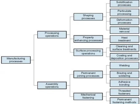
Figure 1: Classification of manufacturing process ... 11
Figure 2: Solidification casting process & Casting product ... 12
Figure 3: Typical sands casting mold method ... 13
Figure 4: Three steps of permanent mold casting ... 13
Figure 5: Molten metal injected die casting ... 13
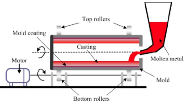
Figure 6: Cylindrical mold spinning of centrifugal casting ... 14
Figure 7: Shows a flowchart of a design process, in which 3D CAD and simulation are used ... 14
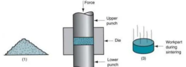
Figure 8: Staring materials (1), Pressed (2) and Sintered (3) ... 16
Figure 9: Cold rolling in material ... 17
Figure 10: Closed and open die forging ... 18
Figure 11: Extrusion process in metal ... 18
Figure 12: Turning tool for removing ... 19
Figure 13: Rotating tool (drill bit) ... 19
Figure 14: Straddle milling ... 20
Figure 15: Surface grinder with horizontal spindle and reciprocating ... 20
Figure 16: The lapping ... 20
Figure 17: Honing tool and its operation ... 21
Figure 18: Schematics of super finishing process ... 21
Figure 19: Electroplating flow reaction ...25
Figure 20: PVD in vacuum chamber ... 26
Figure 21: Overview of CVD process ... 26
Figure 22: Morphology of fusion weld ... 28
Figure 23: Single pass weld on plate ... 29
Figure 24: Multi pass weld in 304 stainless ... 29
Figure 25: Manual welding ... 29
Figure 26: Welding effects- Incomplete fusion ... 31
Figure 27: Inspection using mirror and scale ... 32
Figure 28: Improper welding cracks ... 32
8 | P a g e
Figure 30: Ultrasonic device is manhandled to detect the faults ... 34
Figure 31: Radiographic examination ... 36
Figure 32: Electronic components (PCBs) ... 39
Figure 33: Hand Soldering ... 39
Figure 34: An improperly soldered ... 39
Figure 35: Broken solder joints on a circuit board ... 39
Figure 36: Adhesive device ... 40
Figure 37: Fasteners... 41
Figure 38: Set screw ... 42
Figure 39: Common types of nuts ... 43
Figure 40: Prevailing torque nut ... 43
Figure 41: cylindrical shank solid rivets ... 43
Figure 42: Blind rivets access on both ... 43
Figure 43: Material and energy flow chart of a conventional sand-casting process ... 48
Figure 44: Metal flow in the industry ... 51
Figure 45: Typical energy usage ... 51
Figure 46: Typical energy cost in the industry ... 51
Figure 47: Energy flow using EAC ... 57
Figure 48: Machine driven electricity use as a percentage of delivered energy use by each industry ... 58
Figure 49: Example of process planning systems ... 60
Figure 50: DEMI components in manufacturing process ... 63
Figure 51: Requirements for welding production technology permitting its integration to automatization ... 68
Figure 52: Tensile shear strength of soldered and brazed joints in comparison ... 71
9 | P a g e
List of Tables
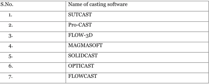
Table 1: List of Simulation Software ... 15
Table 2: Assessment of applicability of lean tools in the steel industry ...45
Table 3: comparison between different furnaces in melting process ... 49
Table 4: Analyzing the casting process using CRIMSON method ...52
Table 5: Comparison between traditional and emerging technology in mechanical fasteners ... 74
10 | P a g e
INTRODUCTION
Chapter 1
Energy Efficiency refers to the amount of output that can be produced with a given input of energy. It generally means the ratio of output in performance, goods & services or energy provided as the input source. Efficient use of energy can be understood in a way that obtain the maximum benefits also imply energy consumption when energy is abundant and cheap. Energy efficiency can be improved at all the points in the chain from energy production to energy consumption.
Manufacturing is defined as the transformation of raw materials into consumer products also leads to the source of environmental pollution. In manufacturing environments, energy efficiency importance has grown and now it is considered among decision-making factors such as productivity, cost and flexibility [1]. The use of energy for industrial operations in Europe is 32% that responsible for emitters of CO2 and climate change. Due to the increase in demand, it increases the usage of natural resources and energy. Energy efficiency is one of the key drivers for developing sustainability and usually sustainability implies the use of energy efficient production methods. In order to achieve this, the manufacturing world implement the concept of gaining maximum resources by applying the minimum capital strategy. Globally, manufacturing has 30% of the energy consumption and by adopting such approaches can save 25 EJ and 37 EJ of energy per year which means that saving energy from 18% to 26% of primary use in industry. Research and development always focused on technological improvements; it leads to have more energy consumption but considering these four attributes creates a key to sustainability. Sustainability must be considered when making manufacturing decisions, it states that manufacturing process are not optimized for energy consumption, resulting in reduction of unnecessary use of energy and resource. Among others, information and communication technologies (ICT) play an important role for measurement, control and improvement of energy efficiency in manufacturing. It includes Supervisory control and Data acquisition systems (SCADA), Manufacturing execution systems (MES), Energy management systems (EMS) and Enterprise resource planning (ERP) systems [22]. However, the problem is in the manufacturing companies is how to use ICT and seamlessly integrate it into the production system.
In most cases, the energy consumption for the various components of the manufacturing systems are considered using average energy consumption models to have discrete event simulation. Reduction of energy leads to save energy without reference to the output produced because the efficiency of the overall system is another problem. To overcome this problem, every process in the manufacturing must be organized. By focusing on both processing and assembly operations, it can implement emerging technologies in each method to improve the efficiency of each process. In overall, analyzing the existing efficient methods of best available technologies and proposing the emerging technical advancements in different possibilities. The advancements are not only in the way of technically advanced also in changing of chemical properties and alternating the components.
11 | P a g e
2. MANUFACTURING PROCESS
Chapter 2
Manufacturing is the process of converting raw materials into finished goods for the consumption or sale. It is a complex process which agitate with people expertise with a wide range of machinery, tools, equipment and automation levels such as robots, computers and other equipment. Technicians should know the importance of basic workshop routines in terms of man labor, materials, methods, revenue and infrastructures which is essential to produce the effective and environment friendly product [1].2.1. PROCESSING OPERATIONS
Processing is a series of mechanical or chemical operations to change the structure or preserve it. It also called as process manufacturing or process production; processing is repeatable in the mass production method of producing products in a continuous flow. In other words, this is a conveyer belt system that produces identical, standardized items at a high rate of speed [2]. Not all the processing is manufacturing produces finished goods for sale mostly in large scale. Under the processing operations, it has three main categories:
1. Shaping process
2. Property enhancing process 3. Surface processing operation
12 | P a g e
2.1.1. SHAPING PROCESS
2.1.1.1. SOLIDIFICATION PROCESS
Solidification is one of the oldest manufacturing processes as it is the primary component for casting process. In the beginning of 2000’s solidification method is the base for many new developments that overcome traditional metal casting. It involves the extraction of heat from the liquid matter transforms into solid matter. The microstructure resulting from this process maybe the final one, in which case it affects the mechanical properties of the product. In other cases, solidification microstructure can be modified by other processes like heat treatment or other processes which leads to have more impact on microstructure [4]
CASTING
Casting process in one of the oldest shaping techniques of manufacturing process and that pours a liquid or semisolid material into a refractory mold cavity until the material gets solid shape. The broad categories are:
Sand casting
The set of channels in which a molten metal flows to the cavity area is called gating system. It consists of a pouring cup and a sprue which allows the liquified metal, runner is a channel which passes the melt to the gates of molten cavity. It may include a feed head (riser)- a cavity connected to the gating system which feeds the casting when it is shrinks [4]. Mold cavity air and gases formed when the metal contacts the surface are eliminated through the vents. The interior cavities of a casting are formed by cores which is made up of sand and baked. This whole frame consists of two parts- cope (upper part) and drag (lower part). A mold cavity is formed by pattern molding once it does the work and the pattern is embedded in sand flask impression. Once the metal become solidified and cooled in desire temperature.
13 | P a g e
Permanent mold casting
Casting process involves pouring a molten metal by gravity into a steel mold. The mold is preheated, coated and the cores are inserted, and mold is closed until it solidifies. The difference between permanent and sand-casting process is sand molds which are broken after each casting, but a permanent casting can be used more than 1000 cycles. Permanent mold casting allows ferrous, non-ferrous metals and alloys [4].
Die casting
Die casting is a permanent mold casting process in which molten metal is injected into mold cavity at an increased pressure. The mold used in this process is called die and the molten metal injection is carried out by die casting machine. High pressure is maintained during the solidification, then mold is opened, and the finished part is removed. Using high pressure in die cavity is making the difference from permanent mold process [4].
Figure 3: Typical sands casting mold method
Figure 4: Three steps of permanent mold casting
14 | P a g e
Centrifugal casting
It is a method of casting process acts by axial symmetry. It involves pouring molten metal into cylindrical mold spinning about its axis of symmetry. The mold is rotating in predetermined speed till the metal has solidified. Steels, graphite and cast irons are used as a mold material [4].
Casting simulation software
Casting simulation is a new technology that allows you to design your casting process on the computer before making expensive molds or patterns and scarps. It helps to visualize on the software about mold filling and solidification casting. It can predict defects like porosity, shrinkage also optimize the quality. Comparing to simulation, conventional techniques is difficult to stimulate for flow and solidification of molten metals. Using simulation, it leads to reduce the usage of resources, higher success rate and by means of customer the lead time is efficient. For industrial application, it would be more useful for manufacturing environment [5][6]. The main inputs for the casting simulation process are:
1. The geometry of the mold cavity (3D model) 2. Thermo-physical properties (related to
temperature)
3. Boundary conditions (heat transfer coefficient) 4. Processing parameters (time, pouring rate)
Figure 6: Cylindrical mold spinning of centrifugal casting
Figure 7: Shows a flowchart of a design process, in which 3D CAD and
15 | P a g e
S.No. Name of casting software
1. SUTCAST 2. Pro-CAST 3. FLOW-3D 4. MAGMASOFT 5. SOLIDCAST 6. OPTICAST 7. FLOWCAST
Among the selected software ProCAST, Flow-3D Cast, MAGMA Soft and Solid Cast are high end simulation packages Which can stimulate most of the metal casting processes.
• ProCAST is provided with QuikCAST solvers which is fast and efficient solution to deal with the fundamentals of any casting process. ProCAST provides full flexibility and porosity predictions are more realistic due to coupled thermal microstructure and porosity calculations.
• Flow-3D cast is accurate in tracking the flow along with the estimation of temperature and locations of defects during the filling process.
• MAGMA Soft forecast casting quality by stimulating mold filling, solidification, cooling and microstructure formation [5][6].
Benefits of casting simulation
• Energy savings
• Improved product quality • Low Refinishing
• Reduces the lead time • Low scarps
• Predicting the metallurgy
16 | P a g e
2.1.1.2. PARTICULATE PROCESSING
Among the various manufacturing technologies, powder processing is the diverse process because of its ability to economically fabricate high-quality processing and complex components to take away tolerances from all materials. It starts with particles having specific attributes of size, shape, packing and converts them into a strong and high-performance component. Process includes the shaping and thermal bonding of the particles using sintering. These two steps can be combined into a single operation in vacuum hot processing and in production, these processes use automated operations with relatively low energy consumption, high material utilization and low capital costs [7]. Powder processing uses a different approach than traditional component. Powder is finely segregated which is combined with other materials such as polymers to forming or create composites. It is widely used for growing and powder-based components are often selected for their low costs but there are having several advantages in quality, homogeneity and performance properties. Basic steps in the particulate process:
1. Preparation of raw material 2. Conversion into particles 3. Drying of particles
4. Classification of particles
5. Blended with a resin and additives 6. Particle furnishing into a mattress 7. Pressing the particles together and
cure the resin
8. Cooling and finishing
2.1.1.3. DEFORMATION PROCESS
Metal working is the process which deals with metals to create individual parts and large sized assemblies or structures. The term includes wide range of work and skills involved to make engine parts, bridges etc. It is commonly classified as
• Hot working operation • Cold working operation
Primary processes such as bulk deformation process used to do the initial breakdown of cast ingots and it implies large amounts of material movement such as rolling, forging. Secondary processes are used to produce the shape of final product using sheet metalworking process which do not involve large amounts of deformation. Deformation leads to massive changes in shape and surface area and it changes the shape of a workpiece by plastic deformation through the application of compressive forces. Adding to shaping of the metal, bulk deformation is used to refine the inhomogeneous structure that results from solidification that are typically hot worked into product forms. This product may be suitable for its intended application, but in many cases, it provides the
17 | P a g e
starting material for secondary deformation processes. Because most processes involve sliding contact between the workpiece and die [8][9].
Hot working operation
Process takes place at approximately 70 to 80% of the melting temperature while working the distorted grain structure produced by deformation is rapidly eliminated by the formation of new strain free grains due to recrystallization. Dynamic recrystallization occurs during deformation then static recrystallization is acted but still the workpiece is hot. For processes such as rolling, forging and extrusion the time within the deformation zone is usually less and grain refinement is usually done by static after hot working. High level of hot deformation followed by holding the workpiece at high temperature tends to static recovery and recrystallization resulting in a fine grain size. It is possible during hot rolling where the time between roll passes and the workpiece slowly cools to the room temperature. It works essentially in constant flow stress, if flow decreases with increasing temperature, metals become ductile and less energy is needed to produce a given amount of deformation.
Cold working operation
Cold working produces better surface finishes, higher strengths, thinner products than hot working but it needs higher forces. It results in deformed structure with the grains extended in the direction of metal flow. A high strength coefficient indicates a high initial resistance of plastic flow and metals with high strength requires a large force of deformation [9].
Advantages:
1. Higher tolerance and good surface finishes
2. Final properties of the workpiece can be controlled 3. High ductility
4. Easier lubrication process
Rolling
Rolling is the compressive deformation process. It consists of two rotating cylindrical rolls for squeezing the thickness of a plate. Simple shapes are to be made in large quantity and it is the most economical process. After ingot casting, rolling is the important metalworking process and most of the wrought steel, aluminum, copper produced using at least one rolling process. During hot rolling, the
18 | P a g e
direction, this leads to have substantial effect on some of the mechanical properties particularly toughness and corrosion resistance. The process can be carried out on different temperature depending on the application and the materials used. After hot rolling many products go through by cold rolling. Usually performed at room temperature, allowed to control the thickness of strip also improving the surface quality. The main advantage of rolling lies in producing expected shapes from large piece of metals at very high speeds.
Forging
During forging, compressive forces are used to deform the metal into a new shape. Two main reasons for forging it improves the properties and homogeneity of microstructure therefore it is used to produce cast ingots for other bulk deformation process such as hot rolling it is the major method used for producing semi-finished shapes. Forging processes described as open-die forging and closed-die [8].
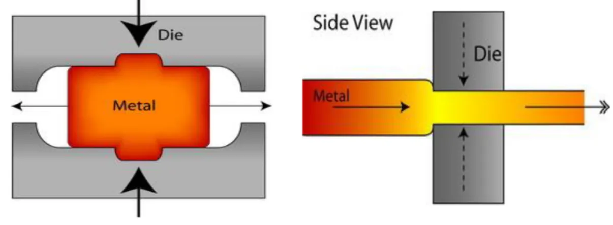
Extrusion
It is a bulk deformation process in which high pressure is given to the metal is reduced by forcing it through a die. During extrusion, the metal billet is forced by a hydraulic system through a die so that the metal is continuously deformed into a long length of metal with the desired cross section. Metals are hot extruded because their resistance to deformation is lower than cold operation and the process is used mainly for producing tubes, bar shapes and irregular shapes.
Figure 10: Closed and open-die forging
19 | P a g e
2.1.1.4. MATERIAL REMOVAL PROCESS
This process is a sharp cutting tool which is used mechanically to remove excess material from the starting piece. Most common application is to shape metal parts and versatile of all manufacturing processes for its capability to produce the geometric features with high precision and accuracy. Casting can also produce different shapes, but it lacks in precision and accuracy compared to machining. This is the most expensive process among other manufacturing process. The most common material removal process is machining, sometimes it referred as traditional and non-conventional machining processes [8][9].
MACHINING
It is a process of material removal in which a sharp cutting tool is used mechanically to cut away material. Machining is the most versatile and accurate of all manufacturing processes to produce a variety of geometries and geometric features. The common application is shaping the metal parts [10][11]. The several processes are:
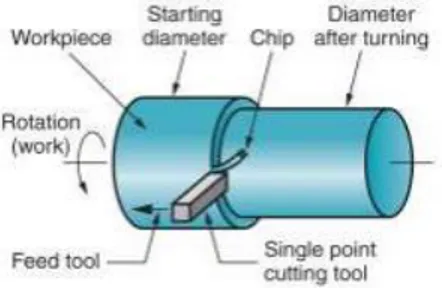
Turning
A cutting tool which removes material from a rotating workpiece to generate a cylindrical shape with the help of machine tool called lathe. It is performing varieties of turning on a lathe- Facing, contour turning, chamfering, cutoff, threading
Drilling
It involves in a process of creating hole in a workpiece by placing a drill bit on the tailstock. Hole making involves high cost components such as engines. The accurate holes are produced by centering, drilling, boring, reaming to improve internal surface and smoothening the tool exit surface of through holes
Figure 12: Turning tool for removing material
20 | P a g e
Milling
In this operation it works as a rotating tool with multiple edges and the axis of tool rotation is perpendicular to feed direction. Milling is an interrupted cutting operation in which has milling cutter, teeth and its so-called milling machine.
Grinding
It is a material removal process in which grinding wheel is disk shaped and balanced for high rotational speeds. It consists of abrasive particles used for cutting and bonding material holds to place the particles in order to establish shape and structure
Lapping
It is also one of the grinding materials used to produce smooth surfaces. It is used in the production of optical lenses, bearings, measuring gauges etc. this process uses an abrasive tool and a fluid suspension having smaller size abrasive particles which vibrates between the work piece and the lapping tool
Figure 15: Surface grinder with horizontal spindle and reciprocating worktable
Figure 16: The lapping process
21 | P a g e
Honing
It is a finishing process with a tool called hone, which carries out a combined rotary and reciprocating motion when the workpiece does not perform in working motion. It is done using on internal cylindrical surface such as automobile cylindrical walls and the honing stones are kept against the workpieces with light pressure [10].
Super finishing
It is an alternative process like honing. It also uses abrasive stick moved with a reciprocating motion and pressed against the surface. The motion between the abrasive stick and the workpiece is varied so that individual grains do not flow in same path. Cutting fluid used in the process for cooling of tool workpiece and the time needed for superfinishing is very less compared to other processes.
2.1.2. PROPERTY ENHANCING
Property enhancing operations are conducted to improve mechanical or physical properties of the work material. The shape is not altered at least unintentionally. Enhancing is executed by the heat treatment process which involves various heating and cooling procedures to do microstructural changes in a material. It can be performed on a metallic part at various times during its manufacturing sequence. Sometimes, this treatment is applied before shaping and used to remove the effects of strain hardening.
2.1.2.1. Heat Treatment
It is the controlled heating and cooling of metals to modify their physical and mechanical properties without changing the product shape [11]. Heat treatment is also associated with increasing the strength of material, manufacturing objectives such as machining, improving formability, restore ductility. This is enabling process that cannot only help manufacturing process, but it can improve the product performance. The principal heat treatments are annealing and hardening.
Figure 17: Honing tool and its operation
22 | P a g e
Annealing
Softening is done to reduce hardness, residual stresses, improve toughness, restore ductility, refine grain size and change the electromagnetic properties of the steel. Restoring ductility or removing residual stresses is a necessary operation when a large amount of cold working is to be performed, such as in a cold-rolling operation or wiredrawing. It consists of heating the metal to a suitable temperature and holding at that temperature for a certain time and slowly cooling [11]. The reasons for annealing are
• Reduce hardness and brittleness
• Alter microstructure to expect the mechanical properties • To soften metals for improved machinability
• To recrystallize cold-working metals • To relieve residual stress
Hardening
It is used to increase the strength and wear properties. One of the essential properties for hardening is carbon and alloy content. If the carbon is enough then the steel can be directly hardened. Otherwise the surface part is carbon enriched using some diffusion treatment hardening techniques
2.1.2.2. Heat treatment method and facilities
Most heat treatment operations are performed in furnaces. We divide this section into two categories of methods and facilities for heat treatment
• Furnaces for heat treatment
• Selective surface hardening methods
Furnaces for heat treatment
It varies depends on heating technology, size, construction and atmosphere control. It usually heats the parts by combination of radiation, convection and conduction. Heating technologies differ by fuel fired and electric heating. A conventional furnace is designed to prevent heat loss and keep the size of the work for further process
Selective surface hardening
It refers to thermochemical treatments applied to steels in which the composition of surface is altered by addition of carbon, nitrogen and other elements. The most used treatments are carburizing and nitriding. It is frequently applied to low carbon steel parts to achieve hard and tough inner core. Carburizing is the most common surface hardening treatment; it involves heating a part of low carbon steel in the presence of a carbon rich environment. Nitriding is a treatment in which nitrogen is diffused into the surfaces of alloy steels to produce a thin hard casing without quenching [11].
23 | P a g e
2.1.3. SURFACE PROCESSING OPERATIONS
To ensure the performance and extended service life of machinery, components need to manufactured not only with high dimensional and accuracy but also with good finishing level. This process used to determine the finishing surface level and it can able to produce the better surfaces than other processes [12]. The main recognized processes are:
2.1.3.1. Cleaning and Surface treatments
Parts must be cleaned to remove oil, dirt or contaminants during the manufacturing sequence. The main reasons for cleaning are to maintain the surface for further processing, remove contaminants that contact the surface, improve hygiene conditions for workers and customers and to increase the performance of the product. Chemical
and mechanical methods are used to accomplish this cleaning process: Chemical
cleaning process use chemicals to remove unwanted particles from the work surface. Mechanical cleaning use certain mechanical operations to remove contaminants from the surface.
Chemical cleaning process
• Alkaline cleaning • Emulsion cleaning • Solvent cleaning • Acid cleaning • Ultrasonic cleaning Alkaline cleaning
It is the most used industrial cleaning method where the products are immersed or sprayed by alkali solutions to remove the contaminants like oil, grease, wax and other particles [12].
Alkaline solutions - sodium hydroxide, potassium hydroxide, sodium carbonate and borax.
Emulsion cleaning
It uses organic solvents dispersed in an aqueous solution in which emulsifiers (soaps) results in two phase cleaning fluid (oil and water) and leads to dissolve the soils on the surface part. Process should be followed by alkaline cleaning to eliminate residues
Solvent cleaning
It uses hot vapors of chlorinated or fluorinated solvents to remove the organic soils such as oil and grease from a metallic surface.
24 | P a g e
Acid cleaning
Acids like hydrochloric, phosphoric, sulfuric acid solutions combined with water solvents, wetting and emulsifiers which is used to remove oils and oxides from metal surfaces. Common applications - soaking, spraying, wiping or manual brushing with elevated temperatures
Ultrasonic cleaning
It combines chemical and mechanical process of cleaning fluid which has high frequency vibrations between 20 and 45 kHz to create cavitation (low pressure vapor bubbles that scrub the surface)
Cleaning fluid contains an aqueous solution immersed in alkaline detergents which is highly effective for removing surface contaminants
Mechanical cleaning process
Physical removal of soils and other particles from the work surface through abrasives or mechanical operations. The processes are:
• Blast finishing • Shot peening
• Mass finishing process
Mass finishing process
Mixing a finishing parts by larger quantity in a container which leads to rub each other to achieve a desired finishing action. Usually parts are small and uneconomical to finish individually compared to mass finishing and this process includes tumbling and vibratory finishing.
Surface Treatment Process
Two processes that alter the surface chemistry of a substrate with foreign atoms • Diffusion
• Ion implantation
Diffusion
• Surface treatment is to get rid of corrosion and oxidation resistance in high temperature.
Siliconizing - Diffusion of silicon into steel surface.
Aluminizing- Diffusion of aluminum into carbon steel and alloy steel. • Surface treatment is to increase hardness and wear resistance.
25 | P a g e
Ion implantation
Embedding of atoms in one or more foreign elements into an eliminating surface using high energy beam of ionized particles which results in alteration of the chemistry and physical properties of layers. Comparing to diffusion, it produces a thinner layer and different concentration.
2.1.3.2. Coating and deposition processes
Coating of a metallic layer into the eliminating surface by an electrolytic process in which metal ions deposited into a cathode work material [12]. The processes are
• Electroplating • Electroless plating • Hot dipping • PVD and CVD
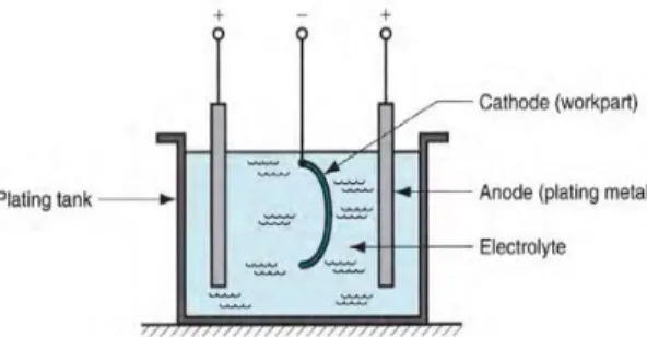
Electroplating
Anode is made and act as a plating metal and cathode is having the electrolyte solutions generated from electrolytic process of metal ions. When direct current passes between anode and cathode it reacts using the electrolytic solution
Electroless plating
The process is completely driven by chemical reactions and no electric current is supplied. Deposition occurs in aqueous solution containing ions of desired plating material and work part surface acts as a catalyst in the presence of reducing agent. Using this process, the metals that can be plated are nickel, copper and gold [12] .
Hot dipping
Subtractive metal part is immersed in a molten bath of a second metal while removing, the second metal goes through coating at first. Common substrate metals are steel, iron and coating metals are zinc, aluminum, tin and lead. Hot dipping processes are
• Galvanizing- It is the most important process in which zinc is coated with steel or iron
• Aluminizing- It is an excellent corrosion protection; in some cases, it is more effective than galvanizing.
26 | P a g e
Physical vapor deposition (PVD)
The process in which a material is converted into vapor using a vacuum chamber and condensed into substrate surface as a very thin film. It is a versatile technology and applicable to unlimited combination. All the physical vapor deposition has following steps:
1. Synthesis of coating vapor 2. Vapor transferred to substrate
3. Condensation of vapors into substrate surface
These steps generally carried out in a vacuum chamber, so evacuation goes through PVD process.
Chemical vapor deposition (CVD)
It involves chemical reactions between a mixture of gases and the pre-heated substrate, ends in depositing a solid film on the substrate. Then the product enlarges and grows on substrate surface to form the coating [12].
2.2. ASSEMBLY OPERATIONS
Domestically, the firm produces the components or ingredients for its product and exported to foreign markets to form a finished product. The firm is saving a transportation
Figure 20: PVD in vacuum chamber
27 | P a g e
costs and custom tariffs because of unassembled equipment than a finished product. Using of local employment which facilitates the integration of firm to foreign market also a benefit for the firm. A foreign production plan used to assemble the components imported from the market and few parts of the products produced in different countries in order to gain each country’s comparative advantage. Intensive parts may be produced in developed countries to use of advanced technologies and labor-intensive assemblies may be produced in developing countries where labor cost is low.
2.2.1. PERMANENT JOINING
Joining consists of many processes which is used to assemble individual parts into a product by using joints. The main function of joints is to transmit or distribute workforces generated from one part to the other parts of the assembly. The selection of an appropriate design to join parts is based on several considerations related to both the product and the joining process. Product related considerations include codes, standards, fitness for service, reliability and unit cost of fabrication. Joining process considerations include material, thickness, joint location and productivity. Designing and manufacturing practice focuses on specifications, variability, randomness is minimized and making non-value-added operations easy as possible. Many product designs are assembled by using design for assembly (DFA) techniques, which is easy developing assembly designs. The aim of DFA is to simply the product cost, improve in quality and reliability along with a reduction in production equipment and inventory parts [11][12].
General guidelines of DFA
• Minimise part count by incorporating multiple functions into single parts • Modifying multiple parts into single subassemblies
• Maximize part symmetry • Provide alignment features
• Provide flats for uniform fastening
• Ensure enough space between fasteners and other features of fastening tool • Standardize to reduce part variety
• Make parts that is easy to identify, and they should be oriented for insertion Generally, a concept design is developed, evaluated and design modifications are made to satisfy the guidelines. There is no guarantee that a given guideline is applicable to a design problem because many of these guidelines are like the rules of current engineering. Joining processes include welding, brazing, soldering, mechanical fastening and adhesive bonding. Mechanical fastening can be used to provide either temporary or permanent joints while permanent joining are mainly used to provide permanent joints.
28 | P a g e
2.2.1.1. WELDING
Welding processes are divided into two broad classes • Fusion welding
• Solid-state welding
Fusion Welding
Fusion welding process involves localised melting, solidification is used normally when joining similar material combinations or materials related to the same family. Weld can be made by melting the edges of the two workpieces and allowing them to join on cooling and it is referred to an autogenous weld. The other method is to add extra material during the welding process through the melting of an electrode. In both cases, the welded area will have a
microstructure property that are different from the
parent metal. The three predominant zones in a fusion welding are the fusion zone, a heat- affected zone (HAZ) and the base metal. The weld deposit itself will have a cast structure and between the weld deposit and the parent metal is an HAZ that did not melt during welding but reached very high temperatures. Joint designs and clearances that trap the beam energy within the joint cavity are preferred for increased process efficiency. In joining thick sections, the preferred joint designs allow the welding metal to freely shrink without causing cracking. In addition, multiple pass welding is used for thick sections to provide for full penetration and the distinctive microstructure of a multiple pass weld compared to a single pass weld [9][10]. To maintain tolerances, distortion due to localized heating and cooling must be controlled during welding by using jigs and fixtures.
Types of Fusion Welding Thermal welding
Heat is provided by an oxyfuel gas flame, usually for manual welding or using thermal reaction for joining heavy sections such as rails. Portability is the main advantage in this process.
29 | P a g e
Electric arc welding
It uses electricity to produce the intense heat for welding. Part of electric arc processes use a consumable electrode that melts, and part of the weld metal is deposited, whereas other parts use a non-consumable
electrode that does not melt, and the weld deposit is not possible. Consumable electrode welding uses a filler rod as an electrode and atmospheric protection of the molten weld metal is provided by a slag which is produced from filler rod or by an externally supplied inert gas. Flux-cored wire alloy is continuous and mechanized operation, that flux is given as powdered form in submerged arc welding for horizontal welding and a resistive slag pool protects the weld zone of thick plates. Inert gas provides the protection in welding processes such as gas metal arc welding (GMAW) and gas tungsten arc welding (GTAW).
Resistance welding
After the pressing process of two parts, electric current passes through the joint to heat and melt the interface. At the same time pressure is kept until solidification of the melt is complete. Spot welding is used in building automotive bodies using welding robots and Seam welding, a continuous stream of spot welds which is used for making beams and box sections [11].
High- energy beam welding
Highly concentrated beams of electrons influence the weld zone in electron beam welding. When the workpiece is surrounded with the gun in a vacuum chamber, a high vacuum protects the surfaces but increases cost and lowers production rates. Welding is possible in outside of chamber. Gas and solid-state lasers usage are increasing in applications for joining also used in making sheets of different thicknesses for tailored blanks used in automobile body construction.
Figure 23: Single pass weld on plate Figure 24: Multi pass weld in 304 stainless
steel
Figure 25: Manual welding method
30 | P a g e
Solid-State Welding
Solid state processes do not involve in melting and solidification process, they are mostly suitable for joining the dissimilar materials. This process also has special joint design or part cross section requirements. For example, continuous drive and inertia friction welding processes require that one of the parts should exhibit a circular section.
Diffusion bonding
It is a solid-state welding process that allows joining the variety of structural materials includes both metals and non-metals. It requires an extremely smooth surface to provide intimate surface contact, a high temperature, a high pressure. Firstly, it allows the contact of the parts with the bond interface followed by plastic deformation of the microscopic surface and then promote diffusion across bond surface. Pressure is applied to maintain the alignment on joint design and clean surfaces are brought into contact. Bond strength is high when the similar metals are mutually soluble but good bonds can be obtained with dissimilar metals. When surface finish is difficult to achieve, a low melting interlayer is inserted between the parts to produce a liquid phase on heating. This liquid phase processed through solidification with the help of diffusion across the solid/liquid interfaces and join the parts. This process is like brazing process
Cold welding
It is a solid-state welding process which needs pressure at room temperature for combining the metals with substantial deformation. It is accomplished by using high pressures on clean interfacing materials and the high pressure can be obtained with simple hand tools when the thin materials are being joined. Dent are usually made in the parts being cold welded and this process is adaptable for joining ductile metals like aluminium and copper [12].
Forge welding
It is a solid-state process which joins the metals by heating them in a forge and by applying pressure it causes permanent deformation at the interface. It is also called hammer welding, forge welds made by blacksmiths by heating the parts to a red heat below the molten temperature. Using of hammer to create pressure at the surfaces to cause coalescence
Friction welding
It is a welding process which produces merging of materials by the heat obtained from mechanically induced sliding motion between rubbing surfaces under certain pressure. It involves in rotating of one part against another to produce frictional heat at the junction. When it meets the required high temperature, rotational motion stops, and additional pressure is applied and then coalescence occurs. There are two variations of friction welding process:
1. In the original process one part is fixed and the other part is rotated by a motor which maintains a constant rotational speed and both parts are meeting in specific period
31 | P a g e
with a specific pressure. To increase the pressure, rotating power is taken out from the rotating piece and once the rotating piece stops working the weld is completed. This process can be controlled by regulating the speed, pressure and time
2. The other process is called inertia welding. Flywheel is revolved by a motor until it reaches a defined speed and it rotates one of the pieces to be welded. The motor is disengaged from the flywheel and the other part to be welded is brought in contact under pressure with the rotating piece.
Both methods utilise the frictional heat and produce welds with similar quality. The main advantages of friction welding are to produce high quality welds in a short cycle time and filler material, flux is not used.
Explosion welding
It is processed by high velocity movement of the parts together to be joined by a controlled detonation. Even though heat is not applied in making an explosion weld it appears that the metal at the interface is molten during welding. Heat comes from several sources like the shock wave associated with impact, from the energy expended in collision also released by plastic deformation associated with jetting and ripple formation. Explosion welding makes a strong weld compared to other metals and it has been used to weld dissimilar metals that cannot be welded by the arc processes.
Hot pressure welding
It is a solid-state process which produces coalescence of materials with heat and pressure to produce macro-deformation of the base metal. The deformation cracks the surface oxide film and increases the areas of clean metal. This type of operation is used in closed chambers where vacuum or a shielding medium is used. Pressure is applied by means of a hot inert gas in a pressure vessel
Welding effects 1.Metallurgic nature • Hot/cold cracks • Lamellar tearing • Inclusions 2.Geometric nature • Excess of welding
• Lack of fusion/incomplete penetration • Misalignment of pieces
• Distortion • Undercutting
32 | P a g e
Monitoring System Visual inspection
It is the most under rated and underestimated method of welding inspection because of its simplicity and absence of sophisticated equipment. It is less expensive and easiest to perform, if this inspection is carried out properly it can be an effective method of acceptable welding quality and preventing welding problems. we need to prevent the welding related problems rather than finding it. Non-destructive testing (NDT) is designed and typically used for the inspection of welding problems when the weld is completed.
Liquid penetrant inspection
It is a low-cost and widely used inspection method for surface-breaking defects and the penetrant is applied for all ferrous and non-ferrous materials. Liquid penetrant is used to detect casting, forging and welding surface defects such as hairline cracks, surface porosity, leaks and fatigue cracks
This inspection is based on capillary action where low surface tension fluid penetrates clean and dry surface. It may be applied to the test component by dipping, spraying or brushing, once the penetration time reaches the excess penetrant is removed, and a developer is applied [8]. The main steps of Liquid Penetrant Inspection:
Figure 27: Inspection using mirror and scale
33 | P a g e
1. Pre-cleaning
2. Application of penetrant 3. Excess penetrant removal 4. Application of developer 5. Inspection
6. Post cleaning
X-ray inspection
The welding work performed by an x-ray welder passes an x-ray inspection. The beam of radiation is examined and kept in normal to the surface material at that point except in special techniques. The length is also examined for each exposure such as thickness of the material, direction of the incident beam which does not exceed the actual thickness. The specimen to be inspected is placed between the source of radiation and the detecting device, the radiation is flows through the part of required length of time to be recorded. The result is a 2-D projection of the part, producing a latent image of varying densities depends upon the amount of radiation in each area. It is known as a radio graph, distinct from a photograph produced by light. Radio graph is examined as a negative and positive as in photography without printing because in printing some of the details is always lost and no useful purpose is served.
Before finalising a radiographic examination, it is always advisable to analyse the component with own eyes to eliminate any possible external defects [8][9]. After the visual analysis, the operator has a clear idea of the possibilities in weld faces which is important for setting up the equipment and for selecting the most appropriate technique.
Figure 29: Using X-ray welder device and featuring result
34 | P a g e
Ultrasonic inspection
It is the testing method which make use of mechanical vibrations as sound waves only in high frequency. A beam of ultrasonic energy is directed into the object to be tested and the beam has insignificant loss except when it is intercepted or reflected. The ultrasonic contact pulse reflection technique is used in this system and it uses a transducer which changes electrical energy into mechanical energy. Transducer connected with high-frequency voltage, which makes a crystal to vibrate mechanically. The vibrations are transmitted into the test piece through the coupling fluid, pulse strikes the test piece and reflected to the point of origin. One of the advantages of this testing is to determine the exact position of a discontinuity in a weld [11]. It requires a high level of operator training and depends on the application of suitable testing procedures.
Monitoring Software
Software application includes base metal selection software, filler metal selection, machine welding, weld automation, tracking, welding code preference, inspection, health & safety and other categories continuously being introduced. For quality assurance it must include the ability of weld mapping and complete traceability. Weld mapping is the process of assigning information for a joint and to enable easy identification of its design, production, quality, and traceability. Welding quality management software that offers a drawing annotation system compliance to ISO 9001 and EN 729 can be achieved with full traceability. Smart welding manager drives the welding aspect of project with standard, keeping everyone informed and organized [9]. Welding project management for
Planning- Welding drawings, symbols, standard Executing- With colourful, graphic weld mapping
Directing- Welders to joints they are qualified to weld and repair Tracking- Materials, welders and inspector progress
Monitoring- Project progress and any required repairs or tests Ordering- Instant access to accurate, timely reports on monitoring Controlling- Password controlled and tracked
Producing- Professional, comprehensive welding project turnover packages Figure 30: Ultrasonic device is manhandled to detect the faults
35 | P a g e
Project management solution
Smart welding manager is a welding and fabrication management application to collaborate and it’s a role based hierarchical system which means access to certain users can be controlled. Online software application is suitable for fabricators of pressure vessels, pressure piping tanks, structural steel and non-steel fabrications
Repositories
Storing and managing the WPS, PQR, WPQ and machine qualifications in one central place with version control and using them across different projects. SWM would allow selection of only the qualified welding procedures. Drawings, test reports and other documents can be stored. It is easy to add data through multiple entry spread sheet style interface and upload files. Manage inventory of materials, consumables, certificates and add them to weld mapping section of the project for traceability.
Weld mapping
Weld mapping is the process of assigning information to a weld joint for traceability. Apart from managing weld mapping through weld design, production, quality and traceability. With the drawing annotation tool, you can create pictorial weld maps to identify the location of weld area. If drawings are revised, annotations can be transferred to the final version.
2.2.1.2. BRAZING AND SOLDERING Brazing
It is a process for joining solid metals by using a liquid metal that melts above 450°C and brazed joint generally results when an appropriate filler alloy is selected. Parent metal surfaces remains clean during heating to the flow temperature of the brazing alloy and a suitable joint design is used which allows capillary action. Joints that are inaccessible and parts that may not be joinable, complicated assemblies of odd shapes can be joined by brazing because of metallurgical incompatibilities. The fact that brazing does not involve any substantial melting of the base metals over other welding processes. It produces less thermal induced distortion than fusion welding. Easy to automate because the heat application does not have to be localised like in fusion welding and application of filler metal is less critical [10]. It utilises a wide variety of heat sources and to achieve brazing temperature and some widely used methods are:
Localised heating techniques
Torch brazing- In this method, the heat is supplied by a fuel gas flame for melting and
flow of filler metal. Fuel gas can be hydrogen, acetylene or propane which is combined with oxygen or air to begin a flame. This is completely automated and requires low capital investment. Torch brazing requires the use of a flux, so a post-braze clean is often required.
36 | P a g e
Induction brazing- High frequency induction heating for brazing is clean, rapid, giving
close control of temperature and location of heat. Heat is created by alternating current which is given into workpiece by an adjacent coil.
Resistance brazing- Heat is generated from resistance to an electric current flowing in
a circuit which includes the workpiece. The process is applicable to simple joints in metals which have high electrical conductivity.
Inspecting brazing joints
Examining finished joints may be the final step in the brazing process but inspection procedures should be incorporated into the design stage [10]. Methodology will depend on the application, service and end user requirements. Acceptance criteria should be defined for any discontinuity with considerations like shape, orientation, location and relationship to other discontinuities.
• Visual examination- For evaluating voids, porosity, surface cracks, fillet size and discontinuous fillets based on metal erosion.
• Leak testing- For determining gas, liquid tightness of brazing and pressure testing involves the application of air at greater service. Vacuum testing is useful for refrigeration equipment and detection of minute leaks.
• Proof testing- Subjecting a brazed joint to a one-time load greater than service level applied by hydrostatic methods and tensile loading.
• Ultrasonic examination- For evaluating joint quality in immersion mode reflection of sound waves by surfaces, using a transducer to produce a pulse and receive echoes.
There are also several destructive and mechanical testing methods often used,
• Peel testing- Useful for evaluating lap joints and production quality control of voids and flux inclusions.
• Metallographic examination- Testing the general quality of joints which detects porosity, poor filler metal flow, base metal erosion and improper fit.
• Tension and shear testing- It determines the joint in tension during qualification or development rather than production.
• Fatigue testing- It tests the base metal of brazed joint as a time consuming and costly method.
37 | P a g e
• Impact testing- It determines the basic properties of brazed joints generally used in a lab setting.
• Torsion testing- It used in brazed joints in production quality control like studs, screws brazed to thick sections.
Soldering
It is a process in which two or more items are joined together by melting a filler metal which has low melting point than the adjoining metals [11]. Unlike welding, it does not involve in melting of work pieces. In brazing, the filler metal melts at a higher temperature, but the work piece metal does not melt.
Solder
Soldering filler materials are available in many different alloys for various applications. In electronics assembly, 63% tin and 37% lead are the choice, other alloys are used for plumbing, mechanical assembly and different applications. Some examples of soft-solder are tin-lead for general purposes, tin-zinc for joining aluminum, lead-silver for strength at higher than room temperature, cadmium-silver for strength at high temperatures, zinc-aluminum for corrosion resistance and tin-silver for electronics. A eutectic formulation has advantages when applied to soldering, the liquid and the solid temperatures are the same so there is no plastic phase and it has the lowest melting point. Having the lowest melting point minimizes heat stress on electronic components during soldering. Common solder formulations based on tin and lead are listed below [10]. The fraction represents percentage of tin first, then lead, totaling 100%
• 63/37: melts at 183 °C (361 °F) (eutectic: the only mixture that melts at a point, instead of over a range)
• 60/40: melts between 183–190 °C (361–374 °F) • 50/50: melts between 183–215 °C (361–419 °F)
For environmental reasons, lead-free solders are becoming more widely used and this is not eutectic formulations, melting at around 250°C making it difficult to create reliable joints with them.
Flux
It is to facilitate the soldering process and the main obstacle is an impurity at the site like dirt, oil or oxidation. It can be removed by mechanical or chemical cleaning, but the temperatures required to melt the filler metal encourage the work piece to re-oxidize. One of the earliest forms of flux was charcoal, which acts as a reducing agent and prevent from oxidation during soldering process and some fluxes provides chemical cleaning. Most common type of flux used in electronics was rosin-based, which is corrosive and non-conductive at normal temperatures. Fluxes for soft solder are currently available in three basic formulations:
38 | P a g e
1. Water soluble fluxes- Higher activity fluxes which should be removed with water after soldering
2. No-clean fluxes- It does not require removal due to the conductive and non-corrosive residues. These fluxes are called no-clean because the residue remains after the solder operation. No-clean flux is available on all 3 classes of PCB’s are defined by IPC-610 it does not inhibit visual inspection and test points
3. Traditional rosin fluxes- It is available in non-activated (R), mildly activated (RMA) and activated (RA) formulations. RA and RMA fluxes contains rosin, which is combined with an activating agent, typically an acid that increases the wettability of metals. The residue resulting from the use of RA flux is corrosive and cleaned.
Processes
There are three forms of soldering, each needs higher temperatures and producing an increasingly stronger joint:
1. Soft soldering which originally used a tin-lead alloy as the filler metal 2. Silver soldering which uses an alloy containing silver
3. Brazing which uses a brass alloy for the filler
Soft soldering
It is characterized by having a melting point of the filler metal of temperature 400°C where silver soldering and brazing use high temperatures and it requires a flame or carbon arc to reach the melting of the filter. Soft solder filler metals are mostly alloys that have liquid temperature below 350°C. In this process, heat is applied to the parts causing the solder to melt and joint the workpieces in a surface alloying process called wetting. In stranded wire, the solder is drawn up into the wire between the strands by capillary action called wicking. Each type of solder has both advantages and disadvantages, because of soft lead and its primary ingredient it is so called soft solder. It is unsuitable for high temperature because it loses strength, melting issues and for mechanical load bearing applications. It is used by jewelers, machinists, plumbing and brazing provides the strongest of the non-welded joints also requires the high temperature to melt the filler metal
39 | P a g e
Silver soldering
Hard or silver soldering is used to join costliest metals like gold, silver, brass and copper. Easy solder contains 56% silver and melting point of 618°C and extra-hard solder has 80% silver and melts at 740°C. It is surrounded by metal which results in a joint that is stronger than metal being joined with perfect flush. Another difference between brazing and soldering is their applying methods, in brazing generally uses rods that are touched to the joint while heating and silver soldering wire are placed on the metal for heating
Induction soldering
It uses induction heating by high-frequency alternating current surrounded by copper coil. It generates current in the part of soldering phase which induces heat because of the higher resistance and the joint can be shaped using copper coils. Solder is placed between the facing surfaces and melts at a low temperature, but considering fluxes are commonly used in induction soldering. This technique is particularly used for continuous soldering in which coils wrap around a cylinder or pipe that needs to be soldered.
Soldering effects
Non-eutectic alloys have a small variation in plastic, but the joint must not be moved until the solder has cooled down using liquidous and solidus temperatures. While inspecting visually, a good solder joint will appear to be smooth and shiny, with the outline of the soldered wire. A matte gray surface is a good indicator of a joint that was moved during soldering and the boundary between the solder and the workpiece in a good joint will have a low angle. Other solder defects can be detected visually as well, in cold solder joints are dull and sometimes cracked. With some fluxes, residues on the joint may need to be removed using water, alcohol or solvents with the parts involved.
Figure 34: An improperly soldered cold joint
Figure 35: Broken solder joints on a circuit board Figure 32: Electronic components (PCBs) Figure 33: Hand Soldering