U
NIVERSITÀ DELLA
C
ALABRIA
Dipartimento di Elettronica,
Informatica e Sistemistica
Dottorato di Ricerca in
Ingegneria dei Sistemi e Informatica
XX ciclo
Tesi di Dottorato
Scheduling Techniques
In High-Speed Packet Switches
UNIVERSITÀ DELLA
CALABRIA
Dipartimento d i Elettronica,
Informatica e Sistemistica
Dottorato d i Ricerca in
Ingegneria dei Sistemi e Informatica
XX
ciclo
Tesi
di
Dottorato
Scheduling Techniques
in High
-
speed Packet Switches
Alessandra Scicchitano
,
J'CT
c c L 4 Q u L 3Coordinatore
Prof. Domenico Talia
Supervisori
Prof. Andrea Bianco
. d$L
-Prof. Antonella Molinaro
Novembre 2007
Prefazione
Packet switches are at the heart of modern communication networks. Ini-tially deployed for local- and wide-area computer networking, they are now being used in different contexts, such as interconnection networks for High-Performance Computing (HPC), Storage Area Networks (SANs) and Systems-on-Chip (SoC) communication. Each application domain, however, has par-ticular requirements in terms of bandwidth, latency, scalability and delivery guarantee. These requirements must be carefully taken into account and have a major impact on the design of the switch.
We propose novel scheduling techniques that enable the construction of distributed (multi-chip) schedulers for large crossbars, develop a scheme for integrated scheduling of unicast and multicast traffic and study flow-control mechanisms that allow switches to achieve lossless behavior while providing fine-grained control of active flows. We also present a comparison between synchronous and asyncronous systems showing that asynchronous switching seems a competitive solution with respect to the more traditional synchronous approach.
Rende,
Indice
1 Introduction . . . 9
1.1 Background . . . 9
1.2 Contributions . . . 10
1.3 Outline of the Thesis . . . 10
2 Packet Switch . . . 13
2.1 General Architecture . . . 13
2.1.1 Switching Fabric . . . 14
2.2 Traffic conditions for a packet switch . . . 16
2.3 Buffering Strategies . . . 17
2.3.1 Output-queued (OQ) . . . 17
2.3.2 Input-queued (IQ) . . . 18
2.3.3 IQ switches with Virtual Output Queueing (VOQ) . . . . 19
2.3.4 Combined Input-Output-Queued (CIOQ) Switches . . . . 21
2.4 Scheduling Unicast Traffic in IQ Switches . . . 22
2.4.1 Optimal Scheduling Algorithm . . . 22
2.4.2 Parallel Iterative Matching Algorithms . . . 22
2.4.3 Sequential Matching Algorithms . . . 25
2.5 Scheduling Multicast Traffic in IQ Switches . . . 26
2.5.1 Queueing . . . 26
2.5.2 Scheduling . . . 27
Parte I A Switching Architecture for Synchronous IQ Switch 3 Distributed Implementation of Crossbar Schedulers . . . 31
3.1 Introduction . . . 31
3.2 Two- vs. three-phase algorithms . . . 31
3.3 Round Trip Time Latencies . . . 32
4 Distributed Scheduler under Unicast Traffic Conditions . . . . 35
4.1 Scheduling algorithms with RTT latencies . . . 35
4.2 Synchronous Round Robin . . . 36
4.3 Performance results . . . 38
5 Distributed Scheduler under Multicast Traffic Conditions . . 41
5.1 Multicast scheduling algorithms . . . 41
5.2 Improved Multicast Round Robin . . . 42
5.3 Performance results . . . 43
6 Distributed Integration of Unicast and Multicast Scheduling 49 6.1 Introduction . . . 49
6.2 Frame Integration . . . 50
6.3 Description of Scheduler . . . 50
6.4 Dynamic Frame . . . 50
6.5 Simulation Result . . . 51
Parte II A Switching Architecture for Asynchronous SANs 7 Introduction to Storage Area Networks . . . 63
7.1 Storage Area Networks . . . 63
7.2 Networking Technologies for SANs . . . 65
7.2.1 Fibre Channel . . . 65
7.2.2 Credit-based flow control . . . 66
8 The Switching Architecture . . . 69
8.1 System Overview . . . 69
8.2 Line-cards . . . 70
8.3 Switching fabric . . . 70
8.3.1 Improvement of multicast scheduling . . . 71
8.4 Control mechanisms for lossless delivery . . . 73
9 Performance Results . . . 75
9.1 Performance results under multicast traffic conditions . . . 75
Parte III Synchronous vs Asynchronous Switching 10 Synchronous versus Asynchronous under Multicast Traffic . 83 10.1 Introduction . . . 83
10.2 System Model . . . 84
Indice 7
Parte IV Conclusion
11 Conclusion . . . 93 Riferimenti bibliografici . . . 95
1
Introduction
1.1 Background
The history of packet-switched networks dates back to the ’60s, when deploy-ment of the ARPANET, ancestor of the Internet, was initiated. In the ’90s the Internet became a global and ubiquitous networking infrastructure, used for business, entertainment and scientific purposes. Since then, the bandwidth demand of the Internet community has been steadily increasing at exponen-tial rates. To satisfy it, researchers and engineers have studied extensively the design of high-performance switching fabrics, that are at the heart of Inter-net routers. Today’s commercial InterInter-net routers offer aggregate bandwidths on the order of terabits per second and employ sophisticated algorithms for packet buffering, processing and scheduling.
The success of this technology has led researchers to investigate its usage in other domains, where the communication subsystem has become a primary performance bottleneck. Packet switching is being used to build interconnec-tion networks for High-Performance Computing (HPC) systems, where a large number of computing nodes and memory banks must be interconnected. It is replacing the traditional bus-based interconnection between servers and storage devices, giving birth to Storage Area Networks (SANs).
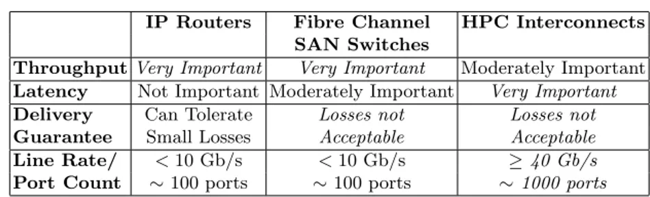
While the benefits of using packet switching in these domains have long been recognized, it is important to remember that each of them has its spe-cific set of requirements, significantly different from those typical of computer networks. Table 1.1 summarizes the requirements for packet switches used in computer networks as well as in the two other domains we are considering. The most significant differences are in terms of latency, aggregate bandwidth and delivery guarantee.
Moreover, current technology trends are playing a significant role in the design of packet switches. Issues such as power consumption, chip I/O band-width limitations and packaging constraints are becoming primary concerns for designers.
IP Routers Fibre Channel HPC Interconnects SAN Switches
Throughput Very Important Very Important Moderately Important Latency Not Important Moderately Important Very Important
Delivery Can Tolerate Losses not Losses not
Guarantee Small Losses Acceptable Acceptable
Line Rate/ < 10 Gb/s < 10 Gb/s ≥ 40 Gb/s
Port Count ∼ 100 ports ∼ 100 ports ∼ 1000 ports
Tabella 1.1. Requirements of domain-specific interconnection networks.
1.2 Contributions
In this thesis we present new scheduling algorithms, aimed at distributed switch implementation and Storage Area Networks respectively. We discuss how the specific requirements of the respective domains and current technol-ogy trends have influenced the design. More importantly, we present some of the architectural innovations that allow them to satisfy the demanding needs of their operating environments.
In Part I we study the distributed implementation of a crossbar sched-uler, considering the effect of big latencies on its performance. Referring to this, we present new scheduling algorithms, both for unicast and multi-cast, that achieve a level of performance that is close to that of a single-chip implementation.
In Part II we discuss the performance of a Storage Area Network under multicast traffic conditions. The architecture presents a number of important features, such as an asynchronous design and the presence of a central arbiter that allow the switch to achieve lossless behavior and isolate congesting flows. Finally in Part III, asynchronous and synchronous switch architectures are compared under multicast traffic.
1.3 Outline of the Thesis
The thesis is organized as follows:Chapter 2 introduces basic concepts and the terminology used in the rest of the thesis. It provides an overview of switching architectures and a brief survey of scheduling algorithms.
Chapter 3 introduces the problem of big latencies for interconnections in multichip implementation.
Chapter 4 is devoted to the specific problem in unicast scenario: how to build schedulers for large crossbars using multiple chips and overcoming the delay and I/O bandwidth limitations caused by distribution.
1.3 Outline of the Thesis 11 Chapter 5 described how to solve the same problem but in a multicast scenario.
Chapter 6 addresses the problem of scheduling unicast and multicast traffic concurrently over a single fabric, achieving high overall performance and providing fairness guarantees.
Chapter 7 opens Part II of the thesis, describing the evolution of the server-storage interface and illustrating how Storage Area Networks improve the organization of storage resources.
Chapter 8 introduces the switching architecture for SANs, focusing in particular on the mechanisms used to achieve loss-free operation and isolate congesting flows.
Chapter 9 contains a simulation-based study of system performance un-der multicast traffic, analyzing the effects of system parameters (buffer sizes, fabric and link speed-up) and traffic characteristics (uniformity, packet size distribution).
Chapter 10 studies differences between synchronous and asynchronous performance under multicast traffic.
2
Packet Switch
In this chapter we introduce the basic concepts and the terminology used in the rest of the thesis. We first present the general architecture of a packet switch and discuss the main distinguishing feature: buffer placement. After an overview of output-queued (OQ), queued (IQ) and combined input-output-queued (CIOQ) switches, we focus on the problem of scheduling uni-cast and multiuni-cast traffic in IQ switches. We provide a survey of the most popular scheduling algorithms and discuss their characteristics in terms of performance and complexity.
Packet switching is a broad field, which has been studied extensively for decades. A comprehensive treatment of the topic can be found in [1], [2] and [3].
2.1 General Architecture
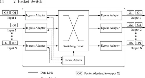
A packet switch is a network device that receives packets on input ports and forwards them on the appropriate output ports. Figure 2.1 shows the architec-ture of a packet switch with N input/output ports. Packets are received on an input port and enter an ingress adapter, where they are stored (if neces-sary) and processed. Processing may include look-up of the destination port, recalculation of header fields (TTL, CRC, etc.) and filtering. Packets are then transmitted through the switching fabric and reach the egress adapters, where they are stored (if necessary) and prepared for transmission on the output links. If the switching fabric operates only on fixed-size data units, variable-size packets have to be segmented on the ingress adapter and reassembled on the egress adapter. Usually an ingress adapter is coupled to an egress adapter and they physically reside on a single board called linecard that can host multiple bi-directional ports.
A switch is synchronous if the linecards and the fabric are coordinated by mean of global clock signal and all ingress adapters start cell transmission at the same time. If the switch is asynchronous, on the contrary, the linecards
Switching Fabric Ingress Adapter Ingress Adapter Ingress Adapter Egress Adapter Egress Adapter Egress Adapter Fabric Arbiter Input 2 O1 O3 O7 O1 O1 O2 O2 ON ON O7 O2 Output 1 Output 2 Output N Input 1 Input N Data Link Control Link
OX Packet (destined to output X)
Figura 2.1. General architecture of a packet switch.
and the fabric work on independent clock domains and transmission from different ingress adapters is not coordinated. In general synchronous switch-es internally operate on fixed-size cells, whereas asynchronous switchswitch-es may natively support variable-size packets. Synchronous architectures are more popular because synchronicity simplifies many aspects of the design and im-plementation of the device. However, asynchronous switches have advantages as well, so they are being actively researched [4, 5, 6]. In the rest of this chapter we will implicitly refer to synchronous, cell-based switches.
2.1.1 Switching Fabric
The switching fabric sets up connections between ingress and egress adapters. It is non-blocking if a connection between an idle input and an idle output can always be set-up, regardless of which other connections have already been established. This is a very desirable property, because it helps the switch in forwarding multiple packets concurrently, thus increasing throughput and reducing latency.
The fabric may run at a higher data rate than the linecards; in this case the ratio between the data rate of the fabric ports and that of the switch ports is called speed-up. For example, in a synchronous switch with speed-up two, at every time slot ingress/egress adapters can transmit/receive two cells to/from the fabric. When speed-up is used, the egress adapters can receive cells from the fabric at a higher rate than they can transmit on the output links, so they need buffers to temporarily store cells in excess. The term speed-up generally refers to the case in which both input and output fabric ports run faster than the switch ports; however, it is possible to have output speed-up only, i.e.
2.1 General Architecture 15 to have only fabric output ports run at a higher data rate. Speed-up on the fabric inputs only is possible but has no practical use.
Crossbar
Output 1 Output 2 Output 3
Crosspoint Output 0 Input 0 Input 1 Input 2 Input 3 Figura 2.2. A 4 × 4 crossbar.
The crossbar is a very simple fabric that directly connects n inputs to m outputs, without intermediate stages. From a conceptual point of view, it is composed by n + m lines, one for each input and one for each output, and n × m crosspoints, arranged as depicted in Figure 2.2. Input i is connected to output j if crosspoint (i, j) is closed.
Every output can be connected to only one input at a time, i.e. at most one crosspoint can be closed on a column. However, one input can be connected to multiple outputs at the same time by closing the corresponding crosspoints on the input row. In this case the signal at the input port is replicated to all the outputs for which the crosspoint is closed. The fabric has intrinsic support for multicast (one-to-many) communication. The crossbar is obviously non-blocking: an idle input (output) has all crosspoints its row (column) open, thus it is enough to close the crosspoint at the intersection to connect them. The simplicity of the crossbar and its non-blocking property make it a very popular choice for packet switches. The main drawback is its intrinsic quadratic complexity, due to the presence of n × m crosspoints. Crossbars implemented on a single chip may also be limited by the amount of I/O signals that must be mapped to chip pins. However, it is possible to build a large multi-chip crossbar by properly interconnecting smaller single-chip ones [7]. The complexity in terms of gates remains quadratic.
2.2 Traffic conditions for a packet switch
The arrival of packets at the switch inputs can be modeled with a discrete-time stochastic process. At every discrete-timeslot at most one fixed-size data unit, called cell can arrive on each input. Variable-size packets can be considered as “bursts” of cells received at the same input in subsequent timeslots and directed to the same output.
We denote with λij the average arrival rate on input i of cells directed to
output j, normalized to the input/output link speed. The offered load from input i is the (normalized) rate at which cells enter the switch on input i and is represented by the termPNj=1λij, where N is the number of input/output
ports. Conversely, the offered load to output j is the (normalized) rate at which cells destined to output j enter the switch and is equal to the sumPNi=1λij.
Traffic is admissible if no input/output links are overloaded, i.e. if the arrival rate at the inputs and the offered load to the outputs are less than or equal to the capacity of the input/output links. Formally, the admissibility conditions can be stated as:
N X j=1 λij ≤ 1 ∀i = 1, . . . , N N X i=1 λij ≤ 1 ∀j = 1, . . . , N
In these conditions it is theoretically possible for the switch to forward to the outputs all the cells it receives on the inputs in finite time.
Traffic is uniform if a cell entering the switch can be directed to any output with equal probability:
λij = 1/N ∀ i, j
It is independent and identically distributed (i.i.d.), also called Bernoulli, if the probability that a cell arrives at an input in a certain timeslot:
• is identical to and independent from the probability that a cell arrives at the same input in a different timeslot AND
• is independent from the probability that a cell arrives at another input. The performance of a packet switch is mainly measured in terms of throughput and latency. Throughput is the (normalized) rate at which the device forwards packets to the outputs, latency is the time taken by a packet to traverse the switch. A switch achieves 100% throughput if it is able to sustain an offered load to all outputs equal to 1, under the hypothesis that traffic is admissible. Multicast traffic
Under unicast traffic conditions, every packet received on input port has direct to just one output port. In multicast traffic, conditions are different.
2.3 Buffering Strategies 17 Traffic generated by a single source and directed to multiple destinations is called multicast. The set of outputs a multicast cell is destined to is called the fanout set and its cardinality the fanout 1. For clarity, we distinguish between
the input cell that is transmitted to the switching fabric and the output cells that are generated by the replication process.
A scheduling discipline is termed fanout splitting if it allows partial service of an input cell, i.e. if the associated set of output cells can be transferred to the outputs over multiple timeslots. No fanout splitting disciplines, on the contrary, require all the output cells associated to an input cell to be delivered at the outputs in the same timeslot. Fanout splitting offers a clear advantage because it allows the fabric to deliver in every timeslot as many cells as possible to the outputs, at the price of a small increase of implementation complexity. The residue is the set of all output cells that lose contention for output ports in a timeslot and have to be transmitted in subsequent timeslots.
2.3 Buffering Strategies
Due to traffic independence, the switch may receive in the same time slot multiple cells directed to the same output. In this case there is a conflict between inputs caused by output contention. It is not possible to forward one of the contending cells and discard all the other, because the drop rate would be unacceptable for any practical application. Therefore, the switch is endowed with internal buffers to store cells that cannot be transmitted immediately on the output link. The buffering strategy, mainly if the cells are buffered before being transferred through the switching fabric or after, is a major architectural trait and strongly influences performance, scalability and cost of a switch [8].
2.3.1 Output-queued (OQ)
In OQ switches all cells arriving at the fabric inputs are immediately trans-ferred through the switching fabric and stored at the outputs. At every times-lot up to N cells directed to the same output can arrive, so the fabric must op-erate with speed-up S = N and the memory bandwidth at each egress adapter must be equal to N times the line rate of the switch ports2 (Figure 2.3).
If multiple cells are buffered at an egress adapter, it is necessary to decide in which order they will be transmitted on the output link. This choice allows the switch to prioritize different flows but does not have an impact on throughput. The OQ switch offers ideal performance, i.e. it achieves 100% throughput under any traffic pattern.
1 The term “fanout” is often used to refer also to the set itself. 2 For simplicity we only consider memory write bandwidth.
N N N 1 1 1 1 1 1 Switching Fabric Input 1 Input N Output 1 Output N Input 2 Output 2
Figura 2.3. An Output-queued switch.
The problem with OQ switches is scalability: fabric speed-up and, above all, egress adapters memory bandwidth, grow linearly with N . As the band-width offered by commercial memories is on the same order of link rates, the OQ architecture is a suitable choice only for systems with a small number of ports or low link rates.
2.3.2 Input-queued (IQ)
In IQ switches the fabric transfers to the egress adapters only cells that can be transmitted immediately on the output links. Those that are blocked because of output contention are buffered on the ingress adapters (Figure 2.4).
1 1 1 1 1 Switching Fabric 1 Output 1 Output N Output 2 1 1 1 Input 1 Input N Input 2 Fabric Arbiter
Figura 2.4. Input-queued switch.
2.3 Buffering Strategies 19 • buffers are not needed on the egress adapters, because at every timeslot the cell received from the switching fabric can be transmitted immediately on the output link3;
• the switching fabric does not need speed-up, because it must be able to deliver at most one cell per timeslot to each egress adapter;
• the memory bandwidth of the buffers on the ingress adapters is equal to the switch ports line rate, irrespective of N , because at most one cell per timeslot arrives at each input;
• a scheduler is required to decide which among multiple cells contending for the same output will be transferred; the fabric must be configured accordingly.
In the simplest case, arriving cells are stored in FIFO queues and each ingress adapter can only transmit the cell that is at the head of its queue. This constraint leads to a phenomenon called “Head-of-the-line (HOL) Blocking”: a cell that is at the head of its input queue and cannot be transferred because of output contention blocks all the other cells in the same queue. Blocked cells may be destined to outputs for which no other input is contending, so the opportunity to transfer a cell is lost. HOL-blocking can severely degrade performance: for large values of N it limits switch throughput to about 58% under uniform i.i.d. traffic [8].
This level of performance is not acceptable, so in the past there have been many attempts to overcome the problem, in general by relaxing the FIFO constraint and allowing the scheduler to consider multiple cells from the same queue. In recent years increased CMOS densities have made feasible a new queueing architecture, called Virtual Output Queueing, that completely eliminates HOL blocking and allows IQ switches to achieve high performance. 2.3.3 IQ switches with Virtual Output Queueing (VOQ)
Virtual Output Queues (VOQs) are sets of independent FIFO queues, each of which is associated to a specific output [9]. In an IQ switch it is possible to avoid HOL-blocking by deploying a set of N VOQs on each ingress adapter (Figure 2.5). With VOQs, cells destined to different outputs can be served in any order and do not interfere with each other; cells destined to the same output, on the contrary, are served with a FIFO policy to preserve the ordering of packets belonging to the same flow.
At every timeslot the scheduler must decide which cells to transfer through the switching fabric, subject to the constraints that at most one cell can depart from an ingress adapter and at most one cell can be delivered to an egress adapter. The problem is equivalent to calculating a matching on a bipartite graph, as illustrated in Figure 2.6. Nodes on the left and right side represent 3 We neglect flow-control issues and assume that a cell can always be transmitted
1 1 1 1 Switching Fabric 1 1 Input N Output N Output 1 Input 1 Q1 Q2 QN Q1 QN Q2 VOQ Set 1 VOQ Set N ... ... Fabric Arbiter
Figura 2.5. Input-queued switch with Virtual Output Queues.
fabric inputs and outputs respectively; dashed lines (edges) represent non-empty VOQs, i.e. cells that can be chosen for transfer. A matching is a set of edges such that each input is connected to at most one output and each output to at most one input.
Matching Problem
VOQ Status A Maximal Matching
Figura 2.6. A Bipartite Graph Matching (BGM) problem.
A matching is maximum size if it contains the highest number of edges among all valid matchings; it is maximal if it is not possible to add new edges without removing previously inserted ones. For instance, the matching shown in Figure 2.6 is maximal but not maximum: no edges can be added, but it is easy to verify that there exists valid matchings with four edges. Edges can be assigned weights, such as the number of cells enqueued in the corresponding VOQ, or the time the cell at the head-of-the-line has been waiting for service.
2.3 Buffering Strategies 21 If weights are defined, the Maximum Weight Matching (MWM) is the one that maximizes the sum of the weights associated to the edges it contains.
IQ switches with VOQs can achieve 100% throughput under any i.i.d. traffic pattern, but only if very sophisticated scheduling algorithms are em-ployed [10]. These algorithms are in general difficult to implement in fast hardware and too complex to be executed in a single timeslot. However, as we will discuss in Section 2.4, a number of heuristic matching algorithms that achieve satisfactory performance with reasonable complexity have been devised. Therefore input-queueing with VOQs is today the preferred architec-ture for the construction of large, high-performance packet switches. From this point on, when discussing IQ switches we will implicitly assume that VOQs are present.
2.3.4 Combined Input-Output-Queued (CIOQ) Switches
OQ and IQ switches represent two diametrically opposing points in the trade-off between speed-up and scheduling complexity. The former employ maxi-mum speed-up but require no scheduling, the latter run without speed-up but need complex schedulers. CIOQ switches (with VOQs) represent an interme-diate point: they buffer packets both at the inputs and at the outputs, employ moderate speed-up S (1 ≤ S ≤ N ) and use simpler schedulers.
Early simulation studies of CIOQ switches showed that, under a variety of switch sizes and traffic patterns, a small speed-up (between two and five) leads to performance levels close to those offered by OQ switches. These hints led a number of researchers to analytically investigate the maximum performance achievable by CIOQ switches. Among the many results that were published, these are particularly significant:
• With a speed-up S = 2 and proper scheduling algorithms, a CIOQ switch can exactly emulate an OQ switch, for any switch size and under any traffic pattern [11, 12]. “Emulating” means producing exactly the same cell departure process at the outputs given the same cell arrival process at the inputs.
• A CIOQ switch employing any maximal matching algorithm with a speed-up of two achieves 100% throughput under any traffic pattern, under the restriction that no input or output is oversubscribed and that the arrival process satisfies the strong law of large numbers [13].
These results prove that with moderate speed-up the performance of an IQ switch can be dramatically improved and that it can even reach the per-formance of an OQ switch if proper scheduling is used. A small fractional speed-up (S < 2) is also typically used to compensate for various forms of overhead, such as additional headers that must be internally prepended to cells and padding imposed by segmentation [14].
2.4 Scheduling Unicast Traffic in IQ Switches
2.4.1 Optimal Scheduling AlgorithmThe optimal scheduling algorithms for an IQ switch, i.e. the one that maxi-mizes throughput, is the Maximum Weight Matching (MWM), when queue lengths are used as weights [15]. McKeown et al. noted that, with this choice of the weights, specific traffic patterns can lead to permanent starvation of some queues [10]. However, they also proved that 100% throughput is still achieved for any i.i.d. traffic pattern if the ages of HOL cells are used as weights; in this case starvation cannot happen. The most efficient known algo-rithm for calculating the MWM of a bipartite graph converges in O(N3log N )
time [16]. Despite polynomial complexity, this algorithm is not practical for high-performance packet switches, because it is difficult to implement in fast hardware and cannot be executed in the short duration of a timeslot. For this reason, a number of heuristic algorithms have been developed.
2.4.2 Parallel Iterative Matching Algorithms
Parallel iterative matching algorithms are the most popular class of heuristic matching algorithms. All inputs in parallel try to match themselves to one output by using a request-grant protocol. VOQ selection at the inputs and contention resolution at the outputs are performed by arbiters (also called se-lectors) using round-robin or random criteria. The process is iterated multiple times, until a maximal matching is obtained or the maximum number of iter-ations is reached. On average these algorithms converge in log2N iterations, but in the worst case they can take N .
PIM
PIM [17] (Parallel Iterative Matching) is one of the first parallel iterative matching algorithms that have been proposed. In every timeslot the following three phases are executed and possibly repeated multiple times:
1. Request: every unmatched input sends a request to every unmatched output for which it has a queued cell.
2. Grant: every output that has been requested by at least one input randomly selects one to grant.
3. Accept: if an input receives more than one grant, it selects randomly one to accept.
The main disadvantage of PIM is that it does not perform well, as it achieves only 63% throughput with a single iteration under uniform i.i.d. traffic. Moreover, it employs random selection, which is difficult and expen-sive to perform at high speed and can cause unfairness under specific traffic patterns [18].
2.4 Scheduling Unicast Traffic in IQ Switches 23 RRM
RRM (Round-Robin Matching) [18] addresses some of the drawbacks of PIM by replacing random selection with round-robin. The selection logic at each input and output is composed by a round-robin selector and a pointer. Pointers at the outputs are named grant pointers, whereas those at the inputs accept pointers.
Every iteration of RRM entails the following three phases:
1. Request: every unmatched input sends a request to every output for which it has a queued cell.
2. Grant: every output that has been requested by at least one input selects one to grant in round-robin order, starting from the position indicated by the grant pointer. The pointer is advanced (modulo N ) to one input beyond the one just granted.
3. Accept: if an input receives more than one grant it selects one to accept in round-robin order, starting from the position indicated by the accept pointer. The pointer is advanced (modulo N ) to one output beyond the one just accepted.
The performance of RRM is very close to that of PIM, so still quite poor. i-SLIP
i-SLIP [19] is a improvement of RRM that, with an apparently minor modifi-cation, achieves much higher performance. The three phases are modified as follows:
1. Request: same as RRM.
2. Grant: every output that has been requested by at least one input selects one to grant in round-robin order, starting from the position indicated by the pointer. The pointer is advanced (modulo N ) to one input beyond the one just granted if and only if the released grant is accepted in the accept phase.
3. Accept: same as RRM.
Moreover, the grant and accept pointers are updated only in the first iteration; a detail that is crucial to prevent starvation of any VOQ under any traffic pattern.
i-SLIP performs extremely well: under uniform i.i.d. traffic it achieves 100% throughput with a single iteration, because it guarantees desynchro-nization of the grant pointers. When the switch is loaded at 100% and traffic is uniform i.i.d, all VOQs are backlogged. Assume that the grant pointers at multiple outputs point to the same input, i.e. they are synchronized. The input receives multiple grants, accepts one and moves the accept pointer. Thanks to the modification of the grant phase, only one of the grant pointers (the one corresponding to the grant that has been accepted) is moved and leaves the
group. For the same reason, at most one new grant pointer can join the group. It is possible to prove that, after a transient period, all grant pointers point to different inputs, regardless of their initial position. A maximum matching is produced at every timeslot and 100% throughput is achieved. Desynchroniza-tion is preserved as long as all VOQs are non-empty, because all the released grants are accepted and so all the grant pointers move “in lockstep”.
Another important feature of i-SLIP is that it is fair and starvation free, i.e. it does not favor some flows over others and guarantees that a cell at the head of a VOQ will be served within finite time.
DRRM
DRRM [20] (Dual Round-Robin Matching) is a further variant of i-SLIP that achieves similar performance with one less phase and less information exchange between the input and the outputs.
The two phases performed in each iteration are:
1. Request: every unmatched input selects one unmatched output to request in round-robin order, starting from the position indicated by a request pointer. In the first iteration, the pointer is updated to one position beyond the input just requested (modulo N ) if and only if a grant is received in the grant phase.
2. Grant: each output that has been requested by at least one input selects one to grant in round-robin order, starting from the position indicated by a grant pointer. In the first iteration the pointer is updated to one position past the input just granted (modulo N ).
A grant phase is not required because each input requests only one output, so it can receive at most one grant, which is automatically accepted.
DRRM achieves 100% throughput under uniform i.i.d. traffic because in this situation request pointers (moved only if a grant is received) desynchro-nize.
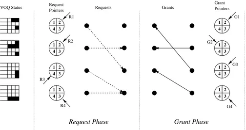
Figure 2.7 shows the operation of the DRRM algorithm for a 4 × 4 switch. At the end of the first iteration all pointers (except R4 and G1) are moved forward by one position. As the matching is maximal, it is not necessary to perform additional iterations.
FIRM
FIRM [21] is an improvement of i-SLIP that achieves lower average latency by favoring FCFS order of arriving cells. It does so by introducing a minor modification in the pointer update rule of the grant phase of i-SLIP: in the first iteration, if a grant is not accepted, the grant pointer is moved to the granted input. The authors also show that this modification reduces the maximum waiting time for any request from (N − 1)2+ N2 to N2.
2.4 Scheduling Unicast Traffic in IQ Switches 25 1 3 4 2 1 3 4 2 1 3 4 2 1 3 4 2 1 3 4 2 1 3 4 2 1 3 4 2 1 3 4 2 Requests Request
VOQ Status Grants Pointers
Grant
Request Phase Grant Phase
Pointers R1 R2 R4 G1 G2 G3 G4 R3
Figura 2.7. The behavior of the DRRM algorithm in a sample scenario.
Weighted Algorithms
As an attempt to approximate the behavior of MWM and improve perfor-mance under non-uniform traffic, heuristic iterative weighted algorithms have been developed. Among these are i-OCF (Oldest Cell First), i-LQF (Longest Queue First) and i-LPF (Longest Port First), proposed by Mekkittikul and McKeown [23].
2.4.3 Sequential Matching Algorithms
Sequential scheduling algorithms produce a maximal matching by letting each input add an edge at a time to an initially empty matching.
RPA [24] (Reservation with Pre-emption and Acknowledgement) and RRGS [25] (Round Robin Greedy Scheduler) are examples of sequential matching algorithms. An input receives a partial matching, adds an edge by selecting a free output and passes it on to the next input. Inputs con-sidered first are favored, because they find most outputs still available. To avoid unfairness, the order in which inputs are considered is rotated at ev-ery timeslot. These algorithms always produce a maximal matching, are fair and can be pipelined to improve the matching rate. However, they require strong interaction among the inputs and introduce latency at low load when pipelined.
The Wavefront Arbiter [26] (WFA) is another popular sequential arbiter. The status of all the N2VOQs of the system is represented in a N ×N request
matrix R: Ri,j= 1 if input i has a cell destined to output j, 0 otherwise. Sets of
they correspond to cells enqueued at different inputs and destined to different outputs. Hence it is possible to produce a matching by sequentially “sweeping” all the diagonals of the request matrix, excluding input and outputs that have already been matched. WFA is fast, simple and offers good performance; however, it suffers from some minor fairness and implementation issues [7].
2.5 Scheduling Multicast Traffic in IQ Switches
In an IQ switch replication can be achieved simply by transmitting cells through the switching fabric multiple times, one for every egress adapter that must be reached. However, the crossbar has intrinsic multicasting capabilities and can replicate a cell to multiple outputs in a single timeslot. A scheduler that takes advantage of this feature can reduce the latency experienced by cells and the load on the fabric input ports, which are occupied for only one timeslot.
In this section we briefly introduce the problem of scheduling multicast traffic and present some of the most popular scheduling algorithms.
2.5.1 Queueing
A multicast cell can be destined to any subset of the N outputs, so the number of possible fanout sets is 2N − 1. Even for moderate values of N it is not
practically feasible to provide a dedicated queue to cells with the same fanout set, therefore HOL-blocking cannot be completely eliminated. Indeed, most architectures store cell arriving on an ingress adapter in a single queue and serve them in FIFO order.
To alleviate HOL-blocking, in [27] the authors propose a windowing scheme that allows the scheduler to access any cell in the first L positions of the queue. This scheme offers throughput improvements, but requires random-access queues, which are complex to implement. Moreover, it is clearly not effective under bursty traffic.
In [28] and [29] the benefits that can be gained by using a small number of FIFO queues at each ingress adapter are investigated. When multiple queues are present, it is necessary to define a queueing policy. Static queueing policies always enqueue cells with a given fanout in the same queue, whereas dynamic policies may enqueue them in different ones, depending on status parameters such as queue occupancy. Static policies lose effectiveness when few flows are active, because most of the available queues may remain empty, whereas dynamic policies lead to out-of-order delivery.
In [32] maximum switch performance is analyzed, under the hypothesis that a queue is provided for every possible fanout set. The results of this work have great theoretical interest, because they show that an IQ switch is not able to achieve 100% throughput under arbitrary traffic patterns, even if it employs this ideal queueing architecture and the optimal scheduling discipline.
2.5 Scheduling Multicast Traffic in IQ Switches 27 2.5.2 Scheduling
The problem of scheduling multicast traffic in an input-queued switch has been addressed by a number of theoretical studies. In [33] and [34] the per-formance of various scheduling disciplines (such as random or oldest-cell-first) is analyzed under different assumptions. Work in [35] studies the optimal scheduling policy, obtaining it for switches of limited size (up to three inputs) and deriving some of its properties in the general case.
In [36] the authors take a more practical approach: they specifically target the design of efficient and implementable scheduling algorithms when FIFO queueing is used and fanout splitting allowed. They provide important in-sight on the problem and propose various solutions with different degrees of performance and complexity. An important observation is that at any times-lot, given a set of requests, all non-idling policies (those that serve as many outputs as possible) transmits cells to the same outputs and leave the same residue. What differentiates one policy from the other is residue distribution, i.e. the criteria with which the set of output cells that have lost contention is partitioned among the inputs. A concentrating policy assigns the residue to as few inputs as possible. Policies exhibiting this property serve in each timeslot as many HOL cells as possible, helping new cells to advance to the head of the queue. As new cells may be destined to idle outputs, throughput is increased. Actually a proof is given that for a 2 × N switch a concentrating policy is optimal, but it cannot be extended to switches of arbitrary size.
The first proposed algorithm, called “Concentrate” implements a purely concentrating policy. However, the authors note that the algorithm suffers from fairness issues, as it can permanently starve queues, so they proceed with the design of TATRA, a concentrating algorithm with fairness guarantees. As TATRA is difficult to implement in hardware, they further propose the Weight Based Algorithm (WBA). WBA is a heuristic algorithm that approximates concentrating behavior by favoring cells with small fanout and guarantees fairness by giving priority to older cells. The algorithm works as follows:
1. At the beginning of every cell time each input calculates the weight of the cell at the head of its queue, based on the age of the cell (the older, the heavier) and the fanout (the larger, the lighter).
2. Each input submits a weighted request to all the outputs that it wishes to access.
3. Each output independently grants the input with the highest weight; ties are broken randomly.
In the specific implementation shown in the paper, the weight is calculated ad W = αA − φF , where A is the age (expressed in number of timeslots), F is the fanout and α and φ are multiplication factors that allow tuning of the scheduler for performance or fairness. Large α implies that older cells are strongly favored, improving fairness, while large φ penalizes cells with large fanout, exalting the concentrating property and thus improving performance.
Calculations show that a cell has to wait at the head of the queue for no longer than (N (φ/α + 1) − 1) timeslots. WBA can be easily implemented in hardware, as reported in the paper.
Parte I
A Switching Architecture for Synchronous IQ
Switch
3
Distributed Implementation of Crossbar
Schedulers
3.1 Introduction
IQ switches are suited for several application domains, such as traditional routers/switches, SANs (Storage Area Networks), and HPC (High-Performance Computing) interconnects; in most of these application domains, a large num-ber of ports and high line rates are dominant and exceed single-chip imple-mentation limits. Multichip impleimple-mentation is limited by power density, gate count, pin count, I/O bandwidth and wiring, due to the high degree of con-nectivity between the input and output selectors [14]. In this thesis we present new scheduling algorithms enabling the construction of schedulers for large switches, while achieving a level of performance that is close to that of a single-chip implementation.
3.2 Two- vs. three-phase algorithms
A very popular solution to determine a heuristic matching is to devise parallel, iterative matching algorithms based on a three-phase (request-grant-accept) [19, 21] or two-phase (request-grant) [44, 36, 20] scheme. Iterative matching algorithms can be classified into two- and three-phase algorithms according to the number of steps per iteration. In three-phase algorithms, there are request, grant, and accept steps in every iteration. In the request phase, every input sends a request to every output it has at least one cell for. In the grant phase, every output independently selects one request to grant. As these decisions are independent, multiple outputs may grant the same input. Therefore, in the third phase, every input selects one grant to accept. Two-phase algorithms, on the other hand, comprise only a request and a grant phase. In the request phase, every input sends a request to one output for which it has at least one cell. In the grant phase, every output independently selects a request to grant. Because every input can receive one grant at maximum, there is no need for an accept phase, i.e., every grant is automatically accepted.
Input and output selection is based on a prioritized round-robin mecha-nism, i.e., the input (output) selector chooses the first eligible output (input) starting from the position indicated by a pointer. The pointer update policy is a crucial characteristic of each algorithm and must be chosen carefully to guarantee performance and fairness. The update policies employed by these algorithms share a common trait: once a connection (corresponding to a VOQ) becomes highest priority, it will be given precedence over the other competing ones until it is established. In i-SLIP this is achieved by having an output grant the same input (in the first iteration) until the grant is accepted. In DRRM, on the contrary, an input will keep requesting the same output (in the first iteration) until it receives a grant. This feature guarantees fairness and leads to pointer desynchronization [18], i.e., it assures that under heavy traffic (when all the VOQs are nonempty) each output grants a different in-put (i-SLIP) or each inin-put requests a different outin-put (DRRM). When this happens, there are no conflicts and a maximum-size matching is produced in every timeslot, leading to 100% throughput.
3.3 Round Trip Time Latencies
Recently, several researchers have addressed the problem of scheduling algo-rithms in input queued switches when considering round trip time latencies in the scheduling process. In [38] round trip latencies are introduced by the need of addressing multi-rack implementation in very large switches. Multi-rack implementation implies that the physical distance between line-cards and the switching fabric is non negligible with respect to the time slot. As such, performance of a centralized scheduler based on the classical iterative three-phase (request-grant-accept) scheme are shown to degrade for large physi-cal distances; a solution to cope with this problem is proposed, being based on a differential signalling scheme and on a slight increase of the scheduler complexity, which is assumed to keep track of VOQs state.
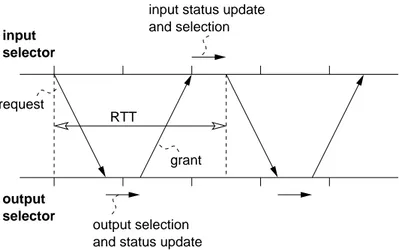
The centralized single-chip implementation of scheduling algorithms is largely dominant; however, scalability problems may arise for very large high-speed switches [39]. When looking at multi-chip implementations, device sep-aration implies that decision taken by input/output selectors belonging to dif-ferent devices are known only after an inter-chip latency, named RTT (Round Trip Time). As such, as shown in Fig. 3.1, information critical i) to determine the matching, ii) to update the pointers and iii) to issue new requests, is de-layed by the inter-chip latency, causing performance degradation. RTTs may be significant with respect to the time slot. Indeed, at high speed the time slot is rather short (13ns at 40Gbit/s for a 64bytes packet) if compared with inter-chip communication latencies which include propagation delays, data se-rialization and pin sharing which may be required to overcome the I/O pin count limit.
3.4 Multi-chip implementation 33
input status update and selection
output selection and status update input selector output selector RTT request grant
Figura 3.1. Round trip time between input and output selectors.
3.4 Multi-chip implementation
Let us focus on iterative schedulers, based on three-phase or two-phase in-formation exchange among inputs and outputs. These schedulers adopt OSs (Output Selectors) to choose among multiple requests received by inputs and ISs (Input Selectors) to select a proper request to issue in a given time slot and to choose among multiple grants received by OSs. Scheduler distribu-tion over several chips entails partidistribu-tioning the selectors used to determine a heuristic matching over physically separated devices. In a single-chip im-plementation, all selectors are tightly coupled and decisions taken at inputs (outputs) are immediately available to outputs (inputs). When dealing with multi-chip implementations, the communication latency between devices im-plies that algorithms devised to run under the hypothesis of having all the scheduling state information available may not be optimal. Indeed, informa-tion needed to update the pointer status or to issue new requests may be known with a delay of some tens of cell time. Performance degradation and loss of fairness were already shown to be a possible problem in this multi-chip scenario.
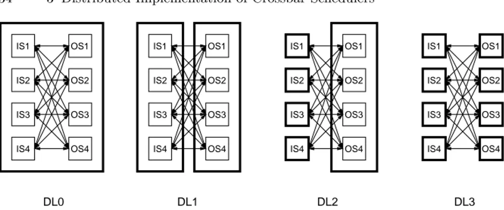
Different levels of selectors distribution could be envisioned, which yield to a different number of physically separated devices, as shown in Fig. 3.2. The first obvious solution to reduce the scheduler complexity, labeled distribution level DL1, is to implement the scheduler in two separate devices, each con-taining respectively N input and N output selectors. This allows to roughly divide by two the scheduler hardware complexity. Another extreme, labeled distribution level DL3, is to distribute the selectors over 2N separate devices, each device implementing one selector. This is referred to as fully distributed solution, which permits a hardware complexity reduction by a factor of N .
IS1 IS4 IS3 IS2 OS1 OS2 OS3 OS4 IS1 IS4 IS3 IS2 OS1 OS2 OS3 OS4 OS1 OS2 OS3 OS4 IS1 IS1 IS4 IS3 IS2 OS4 OS3 OS2 OS1 IS4 IS3 IS2 DL0 DL1 DL2 DL3
Figura 3.2. Distribution levels of a centralized multi-chip scheduler: DL0 is a monolithic, single-chip implementation, DL3 is a fully distributed multi-chip implementation.
As an intermediate step, in [39] a further possible solution is proposed: the N input selectors are physically separated in N devices, whereas all N output selectors are implemented in a single device. This solution has a major draw-back: it reduces the hardware complexity by a factor of two only. However, having the output selectors in a single device permits coordination among output selectors with no delay. This permits to implement schedulers with more iterations in a single cell time, thus preserving good performance for increasing RTTs; however, this limits scheduler scalability. As such, we focus on schedulers suited to a fully distributed multi-chip scenario (distribution level DL3).
4
Distributed Scheduler under Unicast Traffic
Conditions
4.1 Scheduling algorithms with RTT latencies
Dealing with RTTs among devices has a profound impact on scheduler de-sign. In [39], the proposed two-phase scheduler is a direct extension of the DRRM (Dual Round Robin Matching) scheduler[20], originally conceived for a monolithic implementation, to a distributed environment.
Let us briefly summarize DRRM behavior, focusing on an enhanced ver-sion of DRRM which achieves lower delays, thanks to a modified pointer update rule similar to that used in FIRM (Fcfs in Round robin Matching) [21]. In every iteration, first a request is sent by any unmatched input to the first unmatched backlogged output in the round-robin order starting from the current request pointer position. If an output receives more than one request, it grants the one that appears first in the round-robin order starting from the current position of the grant pointer. Request pointers are updated, in the first iteration to point to the output selected in the request phase, and further to one position (modulo N ) beyond the output selected if and only if the request is granted in the first iteration. Grant pointers are updated to one position (modulo N ) beyond the input granted in the first iteration.
In a monolithic implementation, all decisions are taken, and known, in a single time slot, and pointers are updated accordingly. In a distributed imple-mentation, first, request information is delayed by RTT/2 (assuming symmet-ric RTTs) and the request pointer update cannot be performed immediately, since grants will be available RTT/2 slots later. A straightforward extension of DRRM to a distributed scenario would imply that requests to be issued in the next time slot are based on pointer positions not updated, thus breaking the round-robin de-synchronization mechanism and leading to throughput degra-dation. Moreover, request selectors would not be able to accurately know the number of underway grants, thus negatively affecting request decisions.
The distributed extension of DRRM proposed in [39] is based on the fol-lowing ideas. Let us focus on a single iteration case. The key idea to keep the pointer de-synchronization is to ensure that every pointer is updated at most
once every RTT slots. As such, each input and output selector keeps a distinct (request and grant) pointer for every RTT slots. Traditional pointer update rules are used: Request pointers are only updated when the corresponding grant arrives, one RTT after issuing the corresponding request, whereas grant pointers are updated immediately after issuing a grant, since issued grants are accepted by definition. In other words, with respect to a monolithic im-plementation, RTT staggered schedulers are running in pipeline dealing with requests and grants.
This implies that the scheduler complexity (in terms of required pointers) increases linearly with RTT, since RTT pointer registers are required per se-lector. An additional counter (modulo RTT) is needed to indicate the current pointer to be used, whereas the combinatorial selection logic does not need to be duplicated, since a multiplexer to select the proper register among the RTT registers is enough to permit a correct behavior.
Another issue is related to pending requests. Indeed, only after RTT slots it is possible to know whether an issued request was granted. In the mean-time, input selectors should issue further requests. If the number of submitted requests exceeds the number of enqueued cells, it may happen that a slot is reserved for a VOQ that will become empty by the time the grant is received at the input selector, thus wasting system resources. To solve this problem, a PRC (Pending Request Counter) per VOQ plus a request history per input selector are introduced [39]. Basically, new requests are issued only if the num-ber of pending requests is smaller than the numnum-ber of cells currently stored in the corresponding VOQ. This choice, which further complicates the selec-tor design, is fundamental to obtain good performance at low loads or under heavily unbalanced traffic.
Further problems are related to the issue of dealing with more iterations in a single time slot (see [39] for details). We disregard issues related to iterations, which can be reasonably used only if all output selectors share the same physical device. Indeed, iterations are based on the knowledge of the results of previous iterations in the same time slot; in a fully distributed scheduler with RTTs, knowledge of results of previous iterations requires RTT time slots, thus basically preventing the possibility of iterating in this scenario.
4.2 Synchronous Round Robin
Let us now describe the SRR scheduler, initially disregarding issues related to RTT for simplicity. The SRR scheme is based on a cyclic, TDMA-like, preferential scheduling of VOQs. This preferential scheduling is obtained by logically numbering the slots with an incremental counter s, ranging from 0 to N − 1, i.e., a modulo N counter. Slots are logically organized in frames, named SRR frames; each frame comprises N slots.
4.2 Synchronous Round Robin 37 1. the input scheduler associated to input i preferentially selects for a trans-mission the VOQ with destination output |i + s|N. In other words, a
preferential request is issued for output |i + s|N.
2. if the preferential VOQ is empty, a request for the longest VOQ is attempted; ties among VOQs are broken according to a round-robin scheme.
Output schedulers grant the preferential request, if issued; otherwise, a ran-domly chosen request is granted among non-preferential conflicting requests. Other possible solutions exist to break ties among VOQs at input selectors, such as random or round-robin choice among non-preferential VOQs; howev-er, the longest VOQ choice provides the best compromise between complexity and performance, as discussed later. Note that the random choice among con-flicting non-preferential requests at output selectors may be not the most natural choice. Indeed, given that input selectors choose non preferential re-quests exploiting a longest queue first algorithm, output selectors could select the request corresponding to the longest VOQ among conflicting requests. However, this would require an increase in signalling complexity, since VOQ lengths should be sent to output selectors, and also a complexity increase at output selectors, since conflicting request should be compared according to their length. Selecting longest queues at inputs is easier, since queues could be kept simply ordered by length; indeed, in a given time slot, at each input at most one departure and one arrival can occur. Moreover, performance results show that the benefit of the longest queue selection at outputs is marginal for both balanced and unbalanced traffic.
Regardless of the fact that the request is granted or not, a new selection is made in the next time slot, according to the above described algorithm. In summary, for low switch loads SRR behaves similarly to a single-queue FIFO strategy. At high loads, when all queues are always non-empty, the SRR pref-erential scheduling deterministically orthogonalizes input request attempts, so that a single preferential request is received by any output in a given time slot. More precisely, for network loads larger than or equal to the channel capacity, input selectors behave exactly like in a Time Division Multiple Access (TD-MA) scheme: during a SRR frame, whose length is equal to N slots, all inputs have exactly one access opportunity for transmissions toward each output, and they exploit this access opportunity deterministically, thereby avoiding potential conflicts at outputs. In this sense, SRR is throughput optimal under overloaded uniform traffic conditions.
A nice property of SRR is that it can be used without any modification i.e., with no complexity increase, to deal with RTTs. The only difference is that grants will be received one RTT later with respect to request issue, thus negatively affecting delays. However, we will show that even without exploiting any pending request counter, performance at low loads are comparable with those of iterative algorithms exploiting pending request counters.
4.3 Performance results
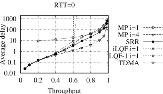
We show performance results based on simulation runs exploiting a propri-etary simulation environment developed in C language. Statistical significance of the results are assessed by running experiments with an accuracy of 1% under a confidence interval of 95%. We compare SRR with the distributed extension of DRRM presented in [39]. The switch has N = 16 inputs and outputs running at the same speed, and is loaded with either Bernoulli or Bursty traffic with geometrically distributed burst sizes with an average burst size of 10 cells; cells in the burst are all directed to the same output. Perfor-mance indices are either average delays vs normalized switch throughput or maximum achievable normalized throughput in overload. SRR performance are reported as solid lines with black dots, the modified version of DRRM, which accounts for multiple pointers to deal with RTTs, is labeled MP (Multi Pointer) and plotted using dashed lines; different symbols refer to a variable number of iterations. 0.01 0.1 1 10 100 1000 0 0.2 0.4 0.6 0.8 1 Average delay Throughput RTT=0 MP i=1 MP i=4 SRR iLQF i=1 LQF-1 i=1 TDMA
Figura 4.1. Performance comparison between SRR, MP, iLQF and TDMA under uniform Bernoulli traffic in a monolithic scheduler implementation (RTT=0).
Let us first examine, in Fig.4.1, a scenario in which RTT=0, which cor-responds to the traditional single-chip implementation of schedulers, under uniform Bernoulli traffic. Besides DRRM and SRR, we plot also a TDMA scheme, iLQF (Longest Queue First) [10] with one iteration, and LQF-1, a simplified version of iLQF with one iteration where inputs send a single request only (for the longest queue) per time-slot to outputs. Note that the TDMA scheme corresponds to SRR using the preferential scheduling only whereas LQF-1 corresponds to SRR using the non-preferential scheduling only. Clear-ly, the preferential scheduling scheme of SRR is fundamental to obtain good performance results at high loads: indeed, iLQF with i = 1 iteration saturates at 0.65, whereas LQF-1 saturates at 0.61. At low loads the non-preferential
4.3 Performance results 39 1 10 100 1000 0 0.2 0.4 0.6 0.8 1 Average delay Throughput RTT=2 MP i=1 MP i=4 MP i=8 SRR 1 10 100 1000 0 0.2 0.4 0.6 0.8 1 Average delay Throughput RTT=4 1 10 100 1000 0 0.2 0.4 0.6 0.8 1 Average delay Throughput RTT=10 1 10 100 1000 0 0.2 0.4 0.6 0.8 1 Average delay Throughput RTT=20
Figura 4.2. Performance comparison between SRR and MP under uniform Bernoulli traffic for variable RTTs.
scheme of SRR becomes dominant, so that performance are close to those of modified DRRM and much better than those of a pure TDMA.
In Fig.5.1 we report delays as a function of the switch throughput for variable RTTs under uniform Bernoulli traffic. No throughput limitations are observed for both SRR and modified DRRM; SRR shows remarkably low de-lays, improving performance as RTT increases. Only a slight delay impairment can be noticed for low-medium loads and small RTTs; this is due to the miss-ing pendmiss-ing request counters, which are instead used in the modified DRMM. Recall that pending request counters are fundamental to avoid issuing too many request for the same VOQ; indeed, if the number of requests issued ex-ceeds the number of enqueued cells, which may happen at low-medium loads and for large RTTs, it may happen that the VOQ becomes empty by the time the grant is received, thus wasting system resources. Indeed, modified DRRM without pending request counters performs much worse, as shown in Fig.4.3, where SRR clearly outperforms the modified DRRM. Moreover, recall that SRR, besides not exploiting any additional counter, does not require any it-eration, thus allowing a fully distributed implementation; nevertheless, delay performance are comparable with those of modified DRRM with logN = 4 iterations, and improve with increasing RTTs. Minor differences exist in this scenario if the non-preferential VOQ choice at inputs in SRR is done on a
1 10 100 1000 0 0.2 0.4 0.6 0.8 1 Avg delay Throughput RTT=4 MP i=1 MP i=4 MP i=8 SRR
Figura 4.3. Performance comparison between SRR and MP under uniform Bernoulli traffic when MP is not using the PRC counters.
1 10 100 1000 0 0.2 0.4 0.6 0.8 1 Avg delay Throughput RTT=4 MP i=1 MP i=4 MP i=8 SRR SRR-RND 10 100 1000 0 0.2 0.4 0.6 0.8 1 Avg delay Throughput RTT=20
Figura 4.4. Performance comparison between SRR and MP under uniform Bursty traffic for variable RTTs.
round-robin basis instead of using a longest queue choice.
Similar performance are shown by SRR for Bursty traffic, as reported in Fig.4.4. Delay properties are remarkable, since SRR shows much better performance than modified DRRM with i = 1 iteration also under correlated traffic. Note that SRR with the random choice of non-preferential VOQs at input selectors, labelled SRR-RND in the plot, show much worse performance than SRR for medium loads, thus justifying the choice of the longest VOQ when the preferential queue is empty.
5
Distributed Scheduler under Multicast Traffic
Conditions
5.1 Multicast scheduling algorithms
We define the fanout set of a multicast cell as the set of outputs to which the cell should be transferred. The cell fanout is the number of outputs in the fanout set. A multicast scheduler may not be able to transfer a multicast cell in a given time slot to all outputs in the cell fanout set, since some outputs may be matched to other inputs by the scheduler. In this case, to enhance performance, most multicast schedulers try to send a copy of the multicast cell to the largest available set of outputs; this is often named fanout splitting discipline. Fanout splitting disciplines may leave a residue, i.e., a copy of the multicast cell that must reach the subset of output ports that were not matched to the given input port in previous time slots.
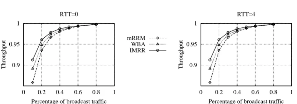
We focus on two previously proposed multicast scheduling algorithms, selected due to their ease of implementation and good performance: WBA (Weight-Based Algorithm) [36] and mRRM [44]. Both rely on a single FIFO queue at each input for multicast. We briefly remind the WBA and mRRM scheduler behavior referring to a scenario where RTT=0 for simplicity. Both schedulers are based on a two-phase request-grant algorithm.
WBA assigns weights to input cells based on their age and fanout at the beginning of every cell time. Once weights are assigned, each OS chooses the heaviest input among those subscribing to it. More precisely, at the begin-ning of every cell time, each IS computes the weight of the new multicast cell/residue at its HOL based on the age of the cell (the older, the heavier), and the fanout of the cell (the larger, the lighter). Then, each IS sends this weight to all outputs that the cell/residue at its HOL wishes to reach. Each OS grants to the input with the highest weight, independently of other out-puts, breaking ties with a random choice. Note that a positive weight should be given to age to avoid input starvation. However, to maximize throughput, fan-out are weighted negatively. Several weight assignments algorithm can be adopted (see [36] for details). We use the weight definition chosen in the sim-ulator available on the Web site at http://klamath.stanford.edu/tools/SIM/:
The cell weight is equal to the number of inputs minus the cell fanout plus the cell age.
Multicast Round Robin (mRRM) was designed to be simple to imple-ment in hardware. A single pointer to inputs is collectively maintained by all outputs. Each output selects the next input that requests it at, or after, the pointer, following a round robin order. At the end of the cell time, the single pointer is moved to one position beyond the first input that is served. However, the single pointer update rule at OSs of mRRM does not permit a fully distributed multi-chip implementation, since output selectors need to be aware of other output selector choice to update the pointer value and this would imply a delay equal to the RTT for pointer update rule that would break the mechanism.
5.2 Improved Multicast Round Robin
Direct extensions of WBA and mRRM can be envisioned to deal with RTTs among input/output selectors induced by multi-chip implementation. Since grants are received at IS with a delay of RTT slots, a multicast cell is at the head-of-the-line for at least RTT slots. To avoid issuing multiple requests for the same cell, thus wasting resources, a number of queues equal to RTT+1 is needed. ISs choose the queue from which the request is issued according to a round-robin fixed scheme among input queues. As such, at most one request per input queue is issued in each RTT. OSs keep working as in the basic WBA and mRRM scheme.
Further extensions can be envisioned and are studied later when presenting simulation results. Indeed, the single FIFO scheme when RTT=0 and its direct extension to RTT+1 FIFO queues when RTT > 0 does not solve the issue of HoL blocking for multicast flows. As such, in some experiments, we introduce a limited number of k = 2 FIFO queues at each input and k = 2 × (RTT + 1) for RTT> 0. In this case, whereas output selectors operate as in the basic scheme, input selectors choose one among the k queues according to queue weights for WBA and to a round-robin scheme for mRRM.
The introduction of more queues at inputs, either to deal with RTTs or to reduce the HoL blocking, introduces the issue of multicast flow assignment to queues. Although several possible assignment strategies were studied in the past [29, 30], in this paper we simply adopt a packet-by-packet load balancing scheme among available queues. We are aware that this may introduce out-of-sequence delivery, but we prefer to avoid studying assignment scheme in this initial work and concentrate on the issue related to dealing with RTTs.
Let us now describe the IMRR (Improved Multicast Round Robin) sched-uler, initially disregarding issues related to RTT for simplicity when a single FIFO queue is available. The same concept of preferential input is kept as in the mRRM algorithm: at each time slot, all output selectors keep a single pointer to a preferential input. However, the pointer update rule is stateless;