Confronto e valutazione della risposta di
sistemi attivi e passivi in reattori
innovativi a fronte di sequenze incidentali
significative ai fini della sicurezza
L. Burgazzi, G. Bianchini, A. Cervone, M. Polidori, F. Giannetti,
D. Vitale Di Maio, T. Murgia, L. Ferroni, A. Naviglio
Report RdS/2013/068 l’energia e lo sviluppo economico sostenibile
CONFRONTO E VALUTAZIONI DELLA RISPOSTA DI SISTEMI ATTIVI E PASSIVI IN REATTORI INNOVATIVI A FRONTE DI SEQUENZE INCIDENTALI SIGNIFICATIVE AI FINI DELLA SICUREZZA
L. Burgazzi, G. Bianchini, A. Cervone, M. Polidori (ENEA), F. Giannetti, D. Vitale Di Maio, T. Murgia, L. Ferroni, A. Naviglio (Università di Roma "La Sapienza")
Settembre 2013
Report Ricerca di Sistema Elettrico
Accordo di Programma Ministero dello Sviluppo Economico -‐ ENEA Piano Annuale di Realizzazione 2012
Area: Produzione di energia elettrica e protezione dell'ambiente
Progetto: Sviluppo competenze scientifiche nel campo della sicurezza nucleare e collaborazione ai programmi internazionali per il nucleare di IV Generazione
Obiettivo: Sviluppo competenze scientifiche nel campo della sicurezza nucleare Responsabile del Progetto: Felice De Rosa, ENEA
Il presente documento descrive le attività di ricerca svolte all’interno dell’Accordo di collaborazione “Sviluppo competenze scientifiche nel campo della sicurezza nucleare e collaborazione ai programmi internazionali per il nucleare di IV generazione” Responsabile scientifico ENEA: Felice De Rosa.
Confronto e valutazione della risposta di sistemi attivi e passivi in reattori innovativi a fronte di sequenze incidentali significative ai fini della sicurezza
Descrittori
Tipologia del documento: Rapporto Tecnico
Collocazione contrattuale: Accordo di programma ENEA-MSE: Piano Annuale di
Realizzazione 2012, Linea Progettuale 1, Obiettivo B: Metodologie avanzate per la valutazione delle conseguenze incidentali, Task B.3 Argomenti trattati: Sicurezza nucleare
Analisi incidentale
Analisi di sicurezza probabilistica
Sommario
Il presente documento riporta le attività svolte nell’ambito della Linea Progettuale 1 (LP1), obiettivo B (Metodologie avanzate per la valutazione delle conseguenze incidentali), task B.3, del PAR 2012, ADP ENEA-MSE.
Lo studio illustra il confronto della risposta dei sistemi di sicurezza attivi e passivi a fronte di sequenze incidentali, relativamente a reattori avanzati di prossima generazione.
In particolare sistemi di sicurezza attivi e passivi che svolgono la stessa funzione di sicurezza, come lo smaltimento del calore residuo e lo spegnimento del reattore, vengono analizzati e comparati a livello di sistema in termini di prestazioni ed affidabilità; il medesimo confronto viene effettuato a livello di sequenze incidentali, in termini di adeguatezza relativamente alle azioni in risposta a determinati eventi iniziatori.
Note:
Questodocumento è stato preparato col contributo congiunto del seguente personale di ricerca ENEA e CIRTEN:
• L. Burgazzi, G. Bianchini, A. Cervone, M. Polidori (ENEA)
• F. Giannetti, D. Vitale Di Maio, T. Murgia, , L. Ferroni, A. Naviglio (Università di Roma “La Sapienza”)
Sigla doc. rif.: CIRTEN-Università di Roma “La Sapienza”: CERSE-UNIRM RL 1185/2013
2 NOME
FIRMA
1 NOME
FIRMA
0 EMISSIONE NOME L. Burgazzi F. De Rosa F. De Rosa
FIRMA
Sommario
L’aumento del grado di sicurezza dei reattori innovativi, come i reattori di quarta generazione, avviene attraverso l'implementazione di caratteristiche di sicurezza intrinseca e passiva nei rispettivi progetti. Una motivazione per l'uso di sistemi passivi per realizzare funzioni di sicurezza, come lo spegnimento del reattore e la rimozione del calore di decadimento, consiste in una maggiore affidabilità per i vantaggi dichiarati di semplicità, riduzione della necessità dell’intervento umano nonché della alimentazione elettrica esterna. Tuttavia recenti studi sollevano preoccupazioni e cautela circa la rivendicata superiorità dei sistemi passivi in termini di prestazioni e relativa disponibilità e affidabilità.. Quindi, come risposta a questo problema, è stata effettuata una valutazione comparativa dei sistemi attivi e passivi in termini, principalmente, dei dati di performance e di affidabilità. A tale scopo la analisi a livello di sistema viene integrata con l'analisi a livello di sequenza incidentale, a seguito della forte interazione tra le prestazioni del sistema e lo scenario incidentale. Per il miglioramento della sicurezza e affidabilità diversi concetti sono presi in esame come il raffreddamento del nucleo con circolazione naturale in caso di station blackout e l'uso di sistemi passivi per lo spegnimento del reattore.
L'analisi evidenzia la rilevanza del valore dell'affidabilità come il più importante fattore nel processo di scelta tra le due alternative: la relativa valutazione è riconosciuta essere ancora un problema aperto, nonostante negli ultimi anni un importante sforzo sia stato fatto dalla comunità internazionale, sia per lo sviluppo che per la valutazione dei sistemi di sicurezza passiva. L'inclusione di potenziali guasti e le stime di affidabilità dei sistemi passivi è pertanto raccomandato in studi probabilistici di valutazione di sicurezza.
In particolare, per quanto riguarda i sistemi a circolazione naturale, i risultati mostrano che la probabilità di guasto della funzione di sicurezza passiva non è da trascurare. Tuttavia con i modelli qui presentati, le ipotesi semplificative e gli scenari limitati considerati, non è ragionevole stabilire che l'affidabilità funzionale per questi sistemi sia tale da impedire l'espletamento della funzione di sicurezza. Ma si può dedurre che attenzione deve essere posta agli aspetti funzionali del sistema passivo, (quelli non appartenenti alla "hardware" del sistema), che può mettere in discussione la loro superiore "accreditata" affidabilità rispetto a quelli attivi.
Sono stati inoltre analizzati i sistemi passivi di spegnimento del reattore con il loro potenziale di migliorare le prestazioni del sistema di protezione del reattore con l'aggiunta di una ulteriore funzione di sicurezza, aumentando l'affidabilità dello “scram” e contribuendo in modo significativo alla affidabilità dell'impianto complessivo. Tuttavia anche in questo caso la mancanza di prove sperimentali e il loro stadio di sviluppo precoce non consente di verificare e validare il prefissato obiettivo di affidabilità, che li rende interessanti per la loro inclusione nel progetto dei reattori innovativi.
A tal proposito è stata effettuata una analisi delle prestazioni dei sistemi di asportazione del calore, sia attivi che passivi, considerando le relative probabilità di fallimento degli stessi, in relazione alle sequenze funzionali che li caratterizzano. Suddette valutazioni sono state effettuate utilizzando la metodologia basata sugli alberi dei guasti in cui si analizzano le possibili modalità di fallimento dei sistemi e/o componenti, che sono stati tenuti in considerazione sia per il funzionamento in modalità attiva, sia per il funzionamento in modalità passiva che in modalità mista. I risultati ottenuti attraverso questa analisi sono stati riportati all’interno del documento al fine di poter confrontare preliminarmente le prestazioni del sistema nelle diverse condizioni.
Alla fine si può concludere che l’affidabilità del sistema passivo non è meglio o peggio di quelli attivi: l’ affidabilità dipenderà dal progetto complessivo e dal funzionamento del sistema, indipendentemente dal fatto che il sistema sia attivo o passivo. Un progetto di buon livello dell'impianto può comprendere sistemi attivi, sistemi passivi, o una combinazione di entrambi i tipi di sistemi per soddisfare gli obiettivi di sicurezza e di prestazioni. Anche se questi sistemi vengono accreditati di una maggiore affidabilità rispetto a quelli "tradizionali" - a causa della minore indisponibilità dovuta ad un guasto hardware - o perfino sono ritenuti “esenti” da guasti, essi pongono tuttavia alcuni problemi per quanto riguarda la la valutazione delle relative prestazioni, in quanto esiste sempre un rischio non nullo del verificarsi di fenomeni fisici che portano a modi di guasto pertinenti.
Table of contents
Executive Summary
1. Introduction and motivation
2. Background on the topic
3. System-based comparison active vs passive
3.1 Decay Heat Removal safety systems 3.2 Reactivity control safety systems
4. Sequence-based comparison active vs passive
4.1 DHR strategy for SFRs
4.2 Demonstrator DHR system requirements and design 4.3 Probabilistic safety analysis
5. Conclusions and recommendations
Executive summary
Safety of innovative reactors, like Gen IV reactors, is expected to be enhanced through the implementation of passive safety features within their designs. A motivation for the use of passive systems to accomplish safety functions, as reactor scram and decay heat removal, is their potential for enhanced safety through increased safety system reliability, because of the claimed advantages of simplicity, reduction of the need for human interaction, reduction or avoidance of external electrical power. However recent studies raise concerns and caution about the claimed superior performance of passive systems and relative higher availability and reliability. Hence, as a response to this concern, a comparative assessment of active and passive systems has been performed in terms, principally, of the expected performance and reliability figures of merit. To this aim the system-based analysis is complemented with the sequence-based analysis, since the strong interaction between the system performance and the accident scenario. For safety and reliability improvement several ideas are included such as the core cooling by natural circulation in case of Station Blackout and the use of passive reactor shutdown systems.
The analysis points out the relevance of the reliability figure of merit as the most important factor in the process of opting out of one system in favor of the other alternative: in fact the relative assessment is recognized as being still an open issue, despite in the recent years an important effort has been made by suppliers, industries, utilities and research organizations on passive safety systems both for their development and assessment. Inclusion of potential failure modes and reliability estimates of passive components for all systems is recommended in Probabilistic Safety Assessment (PSA) studies.
In particular, as regards natural circulation systems, results show that the probability of failure of the passive safety function is not to be neglected. However with the models presented here, the simplifying assumptions and the limited scenarios considered, it is not reasonable to confidentially establish that the functional reliability for these systems is such that it constitutes a challenge for the accomplishment of the safety function. But one can deduce that attention has to be paid to the functional aspects of the passive system, (i.e. the ones not pertaining to the “hardware” of the system), that can challenge their “credited” higher reliability with respect to active ones. SASS (Self Actuated Shutdown Systems) with the potential to improve reactor protection system performance by adding an important safety feature to the defence-in-depth case, while increasing scram reliability and contributing significantly to the reliability of the overall plant, system have been analyzed. However also in this case the lack of experimental evidence and their premature stage of development doesn’t allow to verify and validate the required reliability target, that makes them attractive for their inclusion in the design of innovative reactors.
Concerning this, an analysis has been performed in order to evaluate the heat removal system performance, under all active, passive and hybrid operating modes, considering the corresponding failure rate probabilities, in relation to their functional sequences. These analyses have been carried out through the FTA methodology, in which possible failure modes of components and/or systems, under active, passive or mixed modes have been taken into account. The results obtained through this analysis are reported in the present document to preliminarily compare the performance of the system operating under different conditions.
Lastly one can conclude that passive system reliability is not better or worse than the active ones: reliability will depend on the overall design and operation of the system, regardless of whether the system is active or passive. A good overall plant design may include active systems, passive systems or combination of both types of systems to meet performance and safety objectives. Although these systems are credited a higher reliability with respect to the “conventional” ones - because of the smaller unavailability due to hardware failure - or even they are claimed to be immune from faults, they pose however some challenges as regards the availability/ reliability issues and more in general their performance assessment, because there is always a nonzero likelihood of the occurrence of physical phenomena leading to pertinent failure modes.
1. Introduction and motivation
This study is to be considered as the follow-up of the previous work done throughout the previous year (2012) which emphasized the comparison between active and passive safety systems, to be implemented in advanced nuclear plants, as an important topic to be investigated (ref.1), after the identification of the key issues related to the reliability of passive systems.
This issue has been raised as well by a recent work on the state-of-the-art relative to the passive systems (ref.2), with an attempt to identify the experience lessons, merits, demerits and challenges of the two possible alternatives.
Hence in the present study innovative reactors safety assessment is considered under the focus of a comprehensive comparative assessment between active and passive systems, to accomplish fundamental safety functions, as DHR (Decay Heat Removal) and reactivity control. To this aim some illustrative examples both at the system level and in the frame of PSA (Probabilistic Safety Assessment) context, i.e. sequence-based, are provided and Gen IV reactor are considered mostly, since the implementation in their designs with passive features to cope with safety concerns. In addition to safety systems devoted to DHR, safety systems for reactivity control are being investigated.
2. Background on the topic
Ref.1 lays the foundations for the passive vs active designs assessment, by detailing the relative features and issues with respect to safety requirements, performance and reliability. Henceforth these concepts are briefly recalled, with main focus on passive systems, and some cornerstones for the comparative assessment are briefly delineated.
The design and development of innovative reactors address the use of passive safety systems, i.e. those characterized by no or very limited reliance on external input (forces, power or signal, or human action) and whose operation takes advantage of natural forces, such as free convection and gravity, to fulfil the required safety function and to provide confidence in the plant’s ability to handle transients and accidents. Therefore, they are required to accomplish their mission with a sufficient reliability margin that makes them attractive as an important means of achieving both simplification and cost reduction for future plants while assuring safety requirements with lesser dependence of the safety function on active components like pumps and diesel generators.
On the other hand the concern arising from the factors impairing their performance leads to the consideration that, despite the fact that passive systems “should be” or, at least, are considered, more reliable than active ones - because of the smaller unavailability due to hardware failure and human error - there is always a nonzero likelihood of the occurrence of physical phenomena leading to pertinent failure modes, once the system enters into operation. These characteristics of a high level of uncertainty and low driving forces for heat removal purposes justify the comparative evaluation between passive and active options, with respect to the accomplishment of a defined safety function (e.g. decay heat removal) and the generally accepted viewpoint that passive system design is more reliable and more economical than active system design has to be discussed.
Here are some of the benefits and disadvantages of the passive systems that should be evaluated vs. the correspondent active system.
– Advantages
• No external power supply: no loss of power accident has to be considered.
• The passive nature of the safety systems reduces the reliance on operator action, which could imply no inclusion of the operator error in the analysis. In fact the minimization of the intrinsic complexity of the system results in improved human reliability. The natural circulation core heat removal without, e.g., the incorporation of mechanical pumps results in reduction of operating and maintenance staff requirements, generation of low-level waste, dose rates, and improvement of operational reliability and plant safety and security.
• Passive systems must be designed with consideration for ease of ISI (In Service Inspections), testing and maintenance so that the dose to the worker is much less. • The freedom from external sources of power, instrumentation and control reduces
the risk of dependent failures such as the common cause failures
• Better impact on public acceptance, due to the presence of “natural forces”. • Less complex system than active and therefore economic competitiveness. – Drawbacks
• Reliance on “low driving forces”, as a source of uncertainty, and therefore need for T-H uncertainties modelling.
• Licensing requirement (open issue), since the reliability has to be incorporated within the licensing process of the reactor. For instance the PRA’s should be reviewed to determine the level of uncertainty included in the models and their potential impact. In fact some accident sequences, with frequencies high enough to impact risk but not predicted to lead to core damage by a best estimate t-h analysis, may actually lead to a core damage when t-h uncertainities are considred in the PRA model.
• Need for operational tests, so that dependence upon human factor can not be completely neglected.
• Time response: the promptness of the system intervention is relevant to the safety function accomplishment. It appears that the inception of the passive system operation, as the natural circulation, is conditional upon the actuation of some active components (as the return valve opening) and the onset of the conditions/mechanisms for natural circulation start-up
• Notwithstanding the fact that passive safety systems are claimed to have higher reliability compared with active safety systems, reliability and performance assessment in any case and their incorporation in the reactor concepts needs to be tested adequately, due to several technical issues as formerly pointed out. Quantification of their functional reliability from normal power operation to
transients including accidental conditions needs to be evaluated. Functional failure can happen if the boundary conditions deviate from the specified value on which the performance of the system depends.
• Ageing of passive systems must be considered for longer plant life; for example corrosion and deposits on heat exchanger surfaces could impair their function.
• Economics of advanced reactors with passive systems, although claimed to be cheaper, must be estimated especially for construction and decommissioning.
The question whether it is favourable to adopt passive systems in the design of a new reactor to accomplish safety functions is still to be debated and a common consensus has not yet been reached, about the quantification of safety and cost benefits which make nuclear power more competitive, from potential annual maintenance cost reductions to safety system response. Ref.1 considers both active and passive systems designed to accomplish the required safety functions, as the decay heat removal, for their investigation mainly in terms of the expected safety performance and reliability. An illustrative example of comparative analysis between two different (passive and active) thermal-hydraulic safety systems fulfilling the same heat removal safety function is given and the results of the Station Black Out events’ probabilistic safety assessment for EPR and AP1000 reactors are shown: the analysis revealed various important insights while some significant conclusions have been drawn. removal
With reference to passive systems, it is recognized that their reliability assessment is still an open issue, mainly due to the amount of concerned uncertainties, to be resolved among the community of researchers in the nuclear safety. Moreover a comparative analysis shows that their safety achievement is comparable to or even less than the active systems’ one, since the claimed higher reliability and availability are challenged by some important functional aspects, impairing their performance.
On the other hand the same safety level achieved for active safety system reactors through a higher level of redundancy causes a higher level of complexity of the plant, that is a risk factor itself, and makes the plant vulnerable to common cause of failures.
3. System-based comparison active vs passive
As primary and foremost distinction between the two concepts, passive systems are less susceptible to component failures. Instead they are subject to “inherent failures”, caused by unexpected change in either the internal physical state, such as due to stratification, or in the system environment, such as plugging of heat exchanger tubes.
Conversely active systems are not subject to inherent failures because they can essentially “power” through these phenomena.
It is important to recognize that the reliability of passive safety systems may vary among different accident scenarios. While this can be true of active systems as well, their reliability more often depends on the operation of the equipment, rather than the physical characteristics and thermal-hydraulic details of each accident scenario.
For example an active safety injection system with a centrifugal pump may have uncertainties regarding the ability to model the system and the specific scenario characteristics. However the system’s pumping capabilities are well above the required capabilities. This results in a relatively large functional margin and a negligible contribution by these uncertainties to the likelihood of failure of the system.
On the contrary a passive safety system with relatively smaller capabilities will significantly reduce the available functional margin: as a consequence, the uncertainties in these elements may dominate the reliability of such a passive system.
Consequently the system-based approach should be complemented with the sequence-based approach, since ultimately the accident scenarios are the focus of the analysis rather than the individual passive systems, for safety and licensing purposes.
This research focuses on a different set of reactor technologies examining thermal-hydraulic uncertainties in passive cooling systems, as well as passive shutdown systems behaviour for Generation IV reactors, with regard to the safety level achievement estimation as opposed to active systems. In particular cooled fast reactors have received much of the attention of Generation IV plants.
For Generation IV plant designs, the regulatory concerns are slightly different in the following.
First, a new regulatory regime is under development that may introduce a more risk-informed or even risk-based, licensing and regulatory process. Due to the novelty of the design, especially as regards the utilization of gas or liquid metals as main coolants, as compared to water-cooled reactors, passive system reliability methods may require a more detailed approach than for the current generation of advanced light water reactor designs.
Some of these more advanced plant designs may include even more reliance on passive safety systems or features then the near-term advanced light water reactor designs.
The analysis will be performed consistently with the fact that the Generation IV concepts are at different stages of development and their designs are still evolving.
3.1 Decay heat removal safety systems
This case study refers to a specific Gas-Cooled Fast Reactor Demonstrator (GFRD) system implementing the natural circulation to accomplish the DHR safety function and specifically the ALLEGRO design, under development within the European research program GoFastR (European Gas Cooled Fast Reactor, 2010 to 2013), whose description is offered in references 3 and 4.
The GFRD design promotes the adoption of natural circulation as much as possible to cope with the DHR (Decay Heat Removal) specific challenge, since the reliance on conduction cool-down and radiation, as for HTR for instance, will not work, owing to the high power density, low thermal inertia, poor conduction path and small surface area. Thus the overall DHR strategy is based on the following principles (ref. 5, 6):
• A natural convection flow is preferred following shutdown o This is possible when the circuit is pressurized.
• A forced flow is required immediately after shutdown when depressurized
o This is because the gas density is too low to achieve enough natural circulation and heavy gas injection is helpful; in addition power requirements for the blower are very large at low pressure.
• The primary circuit must be reconfigured to allow DHR
o This implies DHR system activation after a reactor trip by a valve sequence, entailing the isolation of the main loops and the connection across the core of the DHR dedicated loops.
This explains some design criteria and options:
• an upward core cooling flow and a location of the exchangers (DHR and IHX) above the core level;
• a core design criterion based on a low pressure drop (which eases the He circulation); • the use of a guard containment in order to limit the loss of pressure (sufficient backup
pressure) after a primary circuit depressurization;
• the use of dedicated DHR loops, allowing to increase the difference of elevation between the DHR heat exchanger and the core, possibly supported by nitrogen injection in order to enhance the core cooling in natural convection.
• If needed, the primary DHR circuit can operate with a blower, generating a forced circulation in addition to the natural circulation;
• the use of three specific loops (3x100% redundancy) directly connected to the primary vessel, assuming that one could be lost due to the accident initiating event (break for example) and another is assumed unavailable (single failure criterion). The 3 x 100% DHR loop systems are designed to remove 3% of the nominal power.
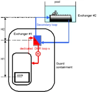
Figure 1 shows a schematic of one out of three systems. The decay heat removal strategy is as follows:
• DHR with natural circulation is proposed for the pressurized case (case of loss of flow combined with a station blackout, where the DHR blowers – which would be launched at first intent - would not be available).
• For the depressurized case, the most attractive option is a combination of active/passive approach to the decay heat removal. In fact the purely passive decay heat analysis suggests that passive heat removal is possible if the system back pressure is high enough to sustain sufficient natural circulation flow through the core and the emergency heat exchanger. If some other mechanism(s) can maintain core cooling in the early phase of a shutdown transient then the requirement can be relaxed for natural circulation cooling (passive cooling) in the later phase of the transient.
Thus, for the first 24-hours after shutdown when natural circulation alone may not be sufficient to cool the core, the system will operate in the active mode with the blower running. With this regard, being the pumping power almost inversely proportional to the square of the gas pressure, the pumping power decreases very significantly when the pressure increases. Therefore an alternative option – while keeping the same forced convection strategy - could be to pre-pressurize the guard containment in order to limit the pumping power requirements, especially as regards scenarios where emergency power supply (such as batteries) is involved. Since the natural circulation mass flow rate through the primary circuit and the corresponding heat removal rate both increase with system pressure, a guard containment structure surrounding the primary system is designed to support an elevated back pressure condition in a depressurization accident.
Like for the main circuit, the DHR secondary loop is a pressurized water loop. The heat is removed from the secondary loop through a horizontal heat exchanger located in a water pool. The water pool is able to act as final heat sink during 24 to 48 hours, if necessary, but would be cooled by an external source after that time.
The intermediate heat exchanger of the decay heat removal loop are calculated according to the two following conservative situations:
• Loss of flow (LOF), with all forced convection unavailable and nominal pressure use (70 bars)
• Loss of coolant gas accident (LOCA), with different back-up pressure levels. In conclusion the DHR strategy relies on:
− natural convection to ensure a diversified functional redundancy for heat removal in case of high pressure scenarios;
− DHR circulation for scenarios at low pressure, with emergency power supply to be able to start and/or to maintain the forced convection. For the long term, due to the close containment, pressure is set to the adequate pressure to ensure natural convection.
Probabilistic analysis
The expected reliability of each system providing the DHR function should be such that the frequency target for the total loss of DHR function should be less than 10-7 per year, consistent with international recommendations for fast reactors (ref.7). The basic DHR function could be jeopardized by several types of fault depending on the operating conditions at the time, including loss of primary coolant inventory, reduction or loss of primary coolant circulation, a loss of coolable core geometry and reduction or loss of heat removal from the primary circuit.
Core coolability and a lack of thermal inertia is a main issue for a helium-cooled fast reactor and this must be taken into account both in the design process and in the safety analysis. In the case of depressurization of the primary circuit it is essential that either forced circulation is maintained within the primary circuit or a minimum pressure adequate for sufficient natural circulation is maintained.
Within a facility, failure of a number of safety devices/components to perform their functions may occur as a result of a single specific cause. Consideration and prevention of such CCF, by provision of DHR systems with adequate diversity and independence, is essential to ensure
adequate reliability levels are achieved. Where redundant systems/components are at potential risk from common cause failures, one means of reducing the susceptibility of the design to such effects is to employ diverse provisions in separate redundant trains or systems. To achieve the required levels of reliability for the DHR function (frequency of total loss of DHR function < 10-7 per year), there should be an adequate diversity strategy, which should ensure that the GFR design will be able to maintain the DHR safety function when required, for all operational and accidental states. The general goal should be to achieve an appropriate level of diversity to enable the exclusion of common cause failures from design basis considerations. In particular, the issue of system/component unavailability during maintenance and repair should be considered.
The analysis refers to the plant configuration following an initiator event requiring the reactor shutdown, as for instance following a loss of off-site power supply accident or a depressurization event due to LOCA in the primary circuit.
Therefore the value of the shutdown frequency (1/ry), should be combined with the probability of the DHR system failure, in order to achieve a final reliability figure. It’s worth noticing that the analysis is performed according to the level of definition of the design (due to the early stage of the design many systems are not yet established); in addition the general lack of statistically reliable data makes somehow difficult the assignment of qualified numerical probabilities to events. The reliability analysis concerns the DHR system performance with regard to both the passive and active operations envisaged for DHR function with reference to the configuration previously set out:
• natural circulation for both pressurized situations with intact helium pressure boundary and in the long term depressurized situations,
• forced circulation in the depressurized situations in the short (24 hours) term decay heat removal in a loss of coolant accident.
In order to limit the loss of pressure in case of primary depressurization and provide the back pressure to sustain natural circulation through the reactor core and the DHR system, a guard containment has been designed to enclose the whole primary system and maintain a pressure
at 10 bar.
The findings are expressed in terms of probability of failure of the systems, to be combined with the corresponding number of system intervention demands per year.
Structural failure of the components (e.g., pipes) leading to loss of coolant and loss of heat exchange process, such as loss of coolable geometries (e.g. alteration of the surface area of heat exchange) are the most relevant causes of system failures. More specifically, the modes of failures of the system operating in natural circulation mode are:
• Piping rupture
• DHX1 failure to operate (“lump” failure mode) to include o DHX1 Shell rupture
o DHX1 multiple tube rupture o DHX1 multiple tube plugging
• DHX2 failure to operate (“lump” failure mode) to include o DHX2 fouling
o DHX2 broken tubes
• Main loop isolation valve failure to close (required to isolate the main primary loop) • DHR loop check valve failure to open (required to activate the circuit operation) • Water tank unavailability (unease to use and reduced effectiveness, due for instance to
ice
formation, high temperature, water make-up failure) • Loss of leak tightness guard vessel (leak tight guard vessel)
Table below shows the failure rates corresponding to the various modes of failure, as regards the system operation in the natural circulation mode, which includes
• a “U” tubes helium/water heat exchanger (DHX1) • a water/water heat exchanger (DHX2)
• isolation valves • check valves • water tank
• leak tight guard vessel
The DHR loop is exclusively relying on natural convection heat transfer, being the isolation valves the only active components, required to isolate the main circuits while a check valve is
supposed to open and activate the loop itself.
The values are taken from relevant databases including data for fission plants, previous works, where applicable (ref. 8, 9) and, if not available, inferred by some kind of “expert” or “engineering judgment” procedure. In any case conservative assumption are adopted. The values in this table are valid for the evaluation of the failure probability of the system, being every failure probability is calculated as λT (T mission time), which is valid for λT<0,1.
Table I. Failure probabilities for passive DHR loop (1 out of 3) Component Failure Mode Failure
rate/h-probability/d
Failure probability
Comment Source reference a
Piping Rupture 3,0E-9/hm 6,5E-6 (3,0E-9/hm)*30m*72h E.A. DHX1 Failure to operate 3,0E-5/h 2,16E-3 (3,0E-5/h)*72h I
DHX2 Failure to operate 8,30E-7/h 5,9E-5 (8,30E-7/h) *72h I Isolation
valve
Failure to close 1,3E-3/d 2,60E-3 (1,30E-3/d)*1demand*2(one inlet and one outlet valve)
I
Isolation valve
Failure to close
CCF 1,3E-3*0,1 1,30E-4 (1,30E-3/d)*1demand *0,1(beta factor to take into account CCF) E.A.
Check valve
Failure to open 1,0E-4/d 1,0E-4 (1,0E-4/d) *1 demand I
Water tank Unavailability 9,3E-7/d 9,3E-7 (9,3E-7/d)*1 demand I Guard
vessel
Failure 1,0E-7/h 7,2E-6 (1,0E-7/h)*72h E.A.
Total system failure probability 6,96E-3
a Reliability data sources: (I) GFR reliability analysis methodology (ref. 6); E.A. Engineering Assessment,
The failure probability for one single loop is accomplished by summing up all the failure probabilities pertaining to the single modes of failure.Mission time of 72 hours is supposed, according to the grace period for the passive systems. The total failure probability for all the three redundant “passive” systems, including the CCFs among the loops, is 1,3E-4.
Conversely, as regards the system operation in the “active” mode, the relative analysis will include also the failure modes associated with the blower required to assure the forced circulation, as shown in Table II. The total failure probability for all the three redundant “active” systems, including the CCFs among the loops, is 1,33E-4: as can be seen the two reliability figures in connection with the two conditions are quite comparable, meaning that the influence of the additional components (that is the blower) to assure the operation in the active mode is unimportant.
Finally, as pointed out in section 2, it would be appropriate to consider additionally the “hybrid” active/passive operation mode, since the system performance in the depressurized condition is driven by the combination of both active (battery-powered blower) and passive means (natural circulation, sustained by backup pressure) respectively in the short (24 hours) and long terms: in this case the failure probability of the system is obtained by the
combination of both active and passive circumstances, by summing up the corresponding probability figures. Table III summarizes the distribution of the failure probabilities by operation mode and corresponding event.
Table II. Failure probabilities for active DHR loop (1 out of 3) Component Failure Mode Failure
rate/h-probability/d
Failure probability
Comment Source reference a
Piping Rupture 3,0E-9/hm 6,5E-6 (3,0E-9/hm)*30m*72h E.A. DHX1 Failure to
operate 3.0E-5/h 2,16E-3 (3,0E-5/h)*72h I
DHX2 Failure to
operate
8,30E-7/h 5,9E-5 (8,30E-7/h) *72h I
Isolation valve
Failure to close 1,3E-3/d 2,60E-3 (1,30E-3/d)*1demand*2(one
inlet and one outlet valve) I
Isolation valve
Failure to close
CCF 1,3E-4/d 1,30E-4 (1,30E-3/d)*1demand *0,1(beta factor to take into account CCF) E.A.
Check valve Failure to open 1,0E-4/d 1,0E-4 (1,0E-4/d) *1 demand I Water tank Unavailability 9,3E-7/d 9,3E-7 (9,3E-7/d)*1 demand I Blower Failure to
operate 1,0E-3/d 1,0E-3 (1,0E-3/d)*1 demand I
Blower Failure to run 1,0E-4/h 7,2E-3 (1,0E-4/h)*72h I Guard
vessel
Failure 1,0E-7/h 7,2E-6 (1,0E-7/h)*72h E.A.
Total system failure probability 1,52E-2
a Reliability data sources: (I) GFR reliability analysis methodology (ref. 6); E.A. Engineering Assessment,
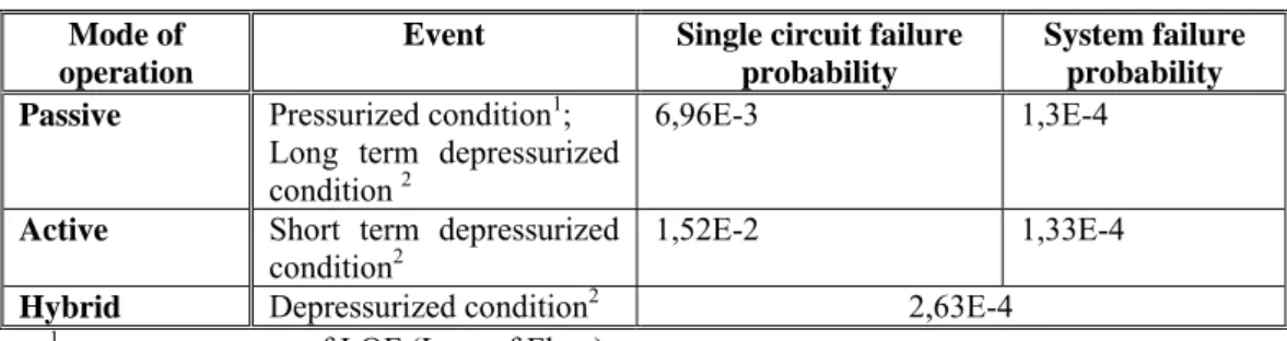
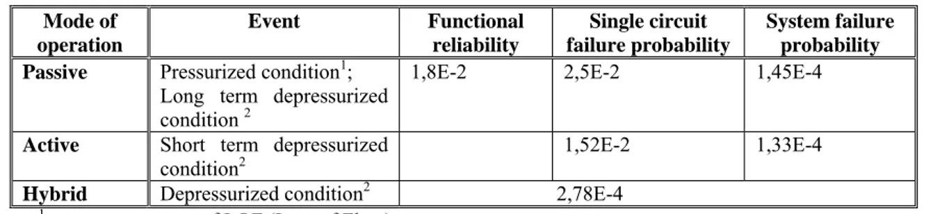
Table III. Summary of reliability results Mode of
operation
Event Single circuit failure probability
System failure probability Passive Pressurized condition1;
Long term depressurized condition 2
6,96E-3 1,3E-4
Active Short term depressurized
condition2 1,52E-2 1,33E-4
Hybrid Depressurized condition2 2,63E-4
1 as a consequence of LOF (Loss of Flow)
2 as a consequence of LOCA (Loss of Coolant Accident)
At the end the total failure frequency for the loss of the DHR function is achieved by combining the unreliability of the envisaged DHR system (either via passive or active units arrangement or hybrid) with the number of demands per year of the system, which can be assumed corresponding to the frequency of any initiating event resulting in system intervention, assumed conservatively equal to 1,0E-1/ry: this results in a failure frequency value which doesn’t meet the sought reliability target of 1,0E-7/ry. This result clearly exhibits the need of implementing additional provisions to achieve the reliability goal to cope with events in order to keep the CDF below 10-6/year at full operating power. This implies that, because of a high reliability target, an appropriate degree of redundancy and diversity has to be introduced into the DHR systems to exclude common mode failures: in fact the analysis stresses the relevance of the CCFs among the different loops of each DHR system on the total reliability.
Additionally the combination of three loops working either in the passive or active mode leads to an operational diversity of the systems for all the operational and accidental states.
Passive system reliability
Up to now the passive system has not been seen from the point of view of the physical process failure. As it is recognized the unreliability of passive systems has mainly two types of contribution. One is from the failure of hardware like coolant boundary failure, referred to as hardware failure. The second contribution, which is usually neglected for active systems, is from uncertainty in achieving the intended design function, referred as functional reliability (ref. 10). This arises from the onset of physical phenomena occurring during the system operation, and by variation of critical parameters which may affect the performance of the system and ultimately lead to its failure. Thus probability of failure of the system due to parameter variations without failure of a component, i.e. functional failure, is a distinguishing characteristic of passive systems, to be addressed within safety and availability analysis. Most methodologies for passive system reliability assessment prompted so far suggest propagation of important system uncertainties through Monte-Carlo simulation of a detailed best estimate mechanistic system (ref.11). Monte-Carlo Simulation (MCS) is well known to be robust to the type and dimension of the problem. Its main drawback, however, is that it is not suitable for finding small probabilities (e.g., PF ≤ 10-3), because the number of samples required to achieve a given accuracy, is proportional to 1/PF. Passive safety systems of innovative nuclear designs are usually designed to meet very high reliability values. As a result, Monte–Carlo simulations incorporated in the functional reliability analysis methodologies should require a large number of system analyses using best estimate system code. Typically mechanistic thermal hydraulic codes of complex nuclear safety systems are computationally expensive and MCS using such models require considerable and often prohibitive computational effort to achieve acceptable accuracy. One common and straightforward approach to reduce computational effort is adopting approximate solutions which require less computational effort for evaluating system response. The simplest and most direct way to tackle this issue is modeling the passive system by relating to the modeling of the unreliability of the hardware components of the system: this is achieved by identifying the hardware failures that degrade the natural mechanisms upon which the passive system relies and associating the unreliability of the components designed to assure the preeminent conditions for passive function performance (ref. 12), e.g. heat exchanger plugging is assumed to impact the degradation of heat transfer coefficient. Thus, the probabilities of degraded physical mechanisms are reduced to unreliability figures of the components whose failures challenge the successful passive system operation. If, on the one hand, this approach may in theory represent a viable way to address the matter, on the other hand, some critical issues arise with respect to the effectiveness and completeness of the performance assessment over the entire range of possible failure modes that the system may potentially undergo and their association to corresponding hardware failures. In this simplified methodology, degradation of the natural circulation process is always related to failures of active and passive components, not acknowledging, for instance, any possibility of failure just because of unfavorable initial or boundary conditions. The adoption of this approach in the present case entails the resorting to the previous analysis, with regard to the system operation in the passive configuration.
Recently, a promising method based on the concept of functional reliability, within the reliability physics framework of load-capacity exceedance (ref.10) has been proposed. The functional reliability concept is defined as the probability of the passive system failing to achieve its safety function as specified in terms of a given safety variable crossing a fixed safety threshold, leading the load imposed on the system to overcome its capacity. In this framework, probability distributions are assigned to both safety functional requirement on a
safety physical parameter (for example, a minimum threshold value of coolant mass flow required to be circulating through the system for its successful performance) and system state (i.e., the actual value of coolant mass flow circulating), to reflect the uncertainties in both the safety thresholds for failure and the actual conditions of the system state. Thus the mission of the passive system defines which parameter values are considered a failure by comparing the corresponding pdfs according to defined safety criteria. Within this method, devised by ENEA, the selection and definition of the probability distributions, that describe the characteristic parameters, are based mainly on subjective/engineering judgment.
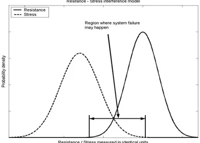
According to the functional reliability approach, illustrated in the previous section, the system is represented with a resistance/stress (R-S) model or load/capacity model, borrowed from reliability physics, with probabilistic density distributions chosen accordingly (see Figure 2), to define the probability of failing to successively carry out a given safety function (e.g. decay heat removal).
Figure 2. Resistance-Stress interference model
In the framework of T-H passive systems reliability assessment, R and S express respectively the safety functional Requirement (R) on a safety physical parameter (for example, a minimum threshold value of He mass flow required to be circulating through the system for its successful performance) and system State (S) (i.e., the actual value of He mass flow circulating). Probability distributions are assigned to both R and S to reflect the uncertainties in both the safety thresholds for failure and the actual conditions of the system state. The function of the passive system defines the safety parameter values that characterize system failure, whose probability is obtained by comparing the state probability density function with that of the defined safety functional requirement. Thus the probability that the achieved He flow rate is less than the required He flow rate to assure the natural circulation is the convolution product of the probability distributions. In our analysis mass flow rate is assumed as characteristic parameter of the system performance and failure criterion is chosen according to relation1:
Zs / Zn ≤ 0,8 (1)
Zs is the actual value
Assuming S and R respectively as the actual mass flow rate and its critical value below which free convection is stopped the probability of failure of the system is given by:
Pf = P(Ws-Wr<0)= ∫∫ f(Ws)f(Wr)dWsdWr (2)
Ws-Wr≤0
Where: Ws actual flow rate value
Wr minimal flow rate value required for natural circulation
(i.e. Wr = Zn *0,8 from eq.1)
f(Ws)f(Wr) is equivalent to the joint probability distribution of the
parameters Wr,Ws (independent individual distributions)
As already stressed the difficulties lie in the definition of the probability distributions
f(Ws)and f(Wr) of S and R respectively, from which the failure probability is derived. In lack
of reliable data, engineering judgment must again be used to obtain such distributions. In order to duly characterize the representative parameter on the probabilistic standpoint (i.e. ranges and distributions), as a general rule, a central pivot has to be identified, and then the range are to be extended to higher and lower values. The pivot value represents the nominal condition for the parameter, and the limits are chosen in order to exclude unrealistic values or those representing a limit zone for the operation demand of the passive system. Probability values are peaked to the nominal value and decrease gradually towards the minimum and maximum allowed values: thus the lower the probability values, the wider the “distance” from the nominal value. On one hand a uniform probability would be suitable to describe the parameter if one considers the design range of the parameter (that is the pdf would be uniform); on the other hand the values of the flow rate could correspond to the end status of a system transient or accident. No finalized study has been carried out to propose the relevant probability distributions. For instance, very simply, such a situation could derive from the occurrence of a failure mode impairing the natural circulation performance, like e.g. thermal stratification: therefore normal distributions are considered, the mean value being the nominal one and confidence limits the ones corresponding to two standard deviations of the mean. It’s worth noticing that the ranges defined by two standard deviations roughly cover the 95% confidence interval, considering that the two-sided 95% confidence interval lies at + 1,96
standard deviations from the mean value.
In this treatment one evaluates the failure probability/unreliability of the free convection by accounting for relationship 1 and 2, considering directly the distribution of the parameter W: this, besides simplifying the problem, allows to go straightforward to the problem.
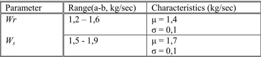
Table below shows the parameters of interest of the normal distributions, with reference to the flow-rate W, across the system. The value of the expected natural circulation flow rate corresponds to the 3% of the flow rate of the reactor operation at full power.
Table IV. Normal pdf characteristics
Parameter Range(a-b, kg/sec) Characteristics (kg/sec)
Wr 1,2 – 1,6 μ = 1,4
σ = 0,1
Ws 1,5 - 1,9 μ = 1,7
As ultimate step the probability value is assessed by solving equation 2: the estimated failure probability of the natural circulation is equal to 1,8E-02. This value is quite dependent on the assumptions taken in the probabilistic model: for instance normal distributions and associated characteristics are postulated to characterize the uncertainties related to the performance parameters. Nevertheless the analysis highlights the natural circulation defiance as a risk factor for the system availability and safety. This value should be integrated with the previous outcome of the reliability analysis concerning passive system reliability, leading in any case to a small deterioration of the whole system reliability, as shown in Table V. The reason for the single loop failure probability significant increase due to functional failure vs the slight growth in system total failure probability, as compared to Table III, lies in the CCF as dominant contributor in the final reliability figure.
Table V. Summary of reliability results (functional reliability included) Mode of operation Event Functional reliability Single circuit failure probability System failure probability Passive Pressurized condition1;
Long term depressurized condition 2
1,8E-2 2,5E-2 1,45E-4
Active Short term depressurized
condition2 1,52E-2 1,33E-4
Hybrid Depressurized condition2 2,78E-4
1 as a consequence of LOF (Loss of Flow)
2 as a consequence of LOCA (Loss of Coolant Accident)
Main findings
Failure probabilities are calculated on various system configurations by integrating the probabilities of occurrence of corresponding hardware components and natural circulation reliability. These results show as well that passive system configuration is more vulnerable to failure than active system configuration, because of their proneness to functional failure, which therefore constitutes a risk factor for the system performance.
3.2 Reactivity control safety systems
This section looks at different special shutdown systems specifically engineered for prevention of severe accidents, to be implemented on Fast Reactors, with main focus on the investigation of the characteristics and performance of passively actuated shutdown systems in Sodium Fast Reactors.
Some innovative approaches suited to improve the overall plant safety have been analyzed, in particular as regards the design options and solutions for passively activated safety devices and/or reactivity feedbacks that would allow the fuel and core design to meet the safety objectives.
The unprotected transients, also denoted as “Anticipated Transients Without Scram” (ATWS) are a group of beyond design basis events that can significantly challenge sodium fast reactors (SFR) safety and are used to categorize the higher probability core disruptive accident (CDA) initiators. This category results from the observation that a small group of high probability events combined with a reactor protection system (RPS) failure (no reactor scram) would lead to coolant boiling and a core melting scenario. The general probability of occurrence for the
initiator events is typically in the range of 0.1 to 0.01 per reactor year and when combined with the probability of RPS failure, 10-6 per reactor year, the probability for an ATWS event is in the range 10-7 to 10-8 per reactor year (ref.13).
These events include: 1) the unprotected transient overpower (UTOP); 2) unprotected loss of primary coolant flow (ULOF); 3) unprotected loss of heat sink (ULOHS); 4) unprotected loss of flow and heat sink; and 5) unprotected safe shutdown earthquake (ref. 14).
Consequently the undesirability of the consequences arising from an unprotected transient, as an energetic core disruptive accident (CDA), vessel failure, and a large early release, has led some SFR designers to consider appropriate measures to avoid the occurrence of this kind of event. One way to protect the plant from such an accident is to include a highly reliable reactor protection system (RPS) by incorporating self-actuated shutdown systems (SASS). For this purpose the conceptual design of candidate passively activated or "self-actuated" reactor shutdown systems, which have been devised during SFR development programs are reviewed. The SASS’ s, pursued during this programs, are, with the exception of their associated hardware, entirely self-contained within the reactor core structure. They incorporate devices which respond inherently to abnormal local process conditions (neutron flux, coolant flow) by passive reactivity feedback devices, thus shutting down the core independently of the RPS.
Current SFR plant protection systems employ two reactor shutdown systems having redundancy of control rod worth and diversity of design. Some of the diversity occurs naturally due to the differing operational requirements of the two systems: the primary system controls reactivity during normal operation, whereas the secondary system is used only to shut down the reactor. Reactor scrams are initiated in response to certain combinations of off-normal signals from sensors which detect neutron flux, sodium temperature, pump speed, etc.. This involves a chain of sub-systems from the sensors, through the logic circuits, amplifiers, electro-magnetic actuators and control rod release mechanisms, culminating in the insertion of the control rods. However, despite proven component reliability, good inspection access and preventive maintenance, there may be a very low probability that an unacceptable change in the fuel element power level or cooling conditions does not result in reactor shutdown. It is argued that the failure of commonly affected links in both of the above-mentioned chains which could possibly occur, for example, during a severe earthquake, requires consideration of events involving inability to scram the reactor. With this possibility, combinations of occurrences could be postulated which might result in a CDA (Core Disruptive Accident). As previously pointed out, particular faulted condition occurrences, of interest could be for instance:
a. Pump loss with failure to scram, referred to as loss of flow (LOF) events,
b. Uncontrolled rod withdrawal with failure to scram, producing a transient overpower (TOP) event.
Under all these circumstances, intensive efforts have led to the introduction of some innovative control systems, to be investigated, with main focus on their performance analysis in order to assess their suitability to meet the safety requirements.
At first the concept of inherent safety vs the concept of passive safety are illustrated and the fundamental functional requirements of the safety systems devoted to the safety shutdown are recalled.
Inherent safety vs passive safety
It is important to underline the difference between inherent safety and passive safety. In fact IAEA, as in ref.15, cautions about the misuse of safety related terms such as passive and inherent safety particularly with respect to advanced nuclear plants, generally without definition and sometimes with definitions inconsistent with each other.
Inherent or Intrinsic Safety refers to the achievement of safety through the elimination or exclusion of specific hazards through the fundamental conceptual design choices made for the nuclear plant. Elimination of all these hazards is required to make a nuclear power plant inherently safe. Since this appears to be impossible, it is recommended to avoid the unqualified use of "inherently safe" for an entire nuclear power plant or its reactor.
On the other hand, a reactor design in which one of the inherent hazards is eliminated is inherently safe with respect to the eliminated hazard. An inherent safety characteristic is a fundamental property of a design concept that results from the basic choices in the materials used or in other aspects of the design which assures that a particular potential hazard can not become a safety concern in any way. In this case no changes of any kind, such as internally or externally caused changes of physical configuration can possibly lead to an unsafe condition. When an inherent hazard has not been eliminated, engineered safety systems, structures or components are provided in a design to make its use acceptable without undue risk. Such provisions generally aim to prevent, mitigate, or contain potential accidents.
On the other hand the concepts of active and passive safety describe the manner in which engineered safety systems, structures, or components function and are distinguished from each other by determining whether there exists any reliance on external mechanical and/or electrical power, signals or forces. The absence of such reliance in passive safety means that the reliance is instead placed on natural laws, properties of materials and internally stored energy.
Thus inherent safety characteristic refers to the safety achieved by the elimination of a specified hazard by means of the choice of material and design concept, while passive safety feature refers to the safety achieved by the operation of a passive system, i.e. which does not need any external input to operate.
The adoption of these self actuated safety systems obeys more to the inherent safety principle, which is the pursuit of designing hazards out of a process, as opposed to using engineering or procedural controls to mitigate risk. Therefore the plant design safety is improved inherently because of its essential characteristics, those which belong to the process by its very nature, making possible to avoid and remove hazards rather than to control them by relying on “add-on” safety features, in particular by eliminating or reducing their likelihood of occurrence. Unfortunately the lack of information complicates the evaluation of the inherent safety and the judgment of a reliability figure. As initial step, it is important to analyse the factors that may affect the inherent safety of the plant, by systematically evaluating the inherent safety characteristics. This could be achieved by identifying the basic principles of inherent safety to be described at first as parameters and finally as inherent safety indexes. For instance, from the various system description temperature and pressure are parameters suitable to illustrate the inherent safety as direct measures of the specific intrinsic property.
In general passive and inherent safety devices may, between other measures, contribute to reduce the probability of a CDA and, to a large extent, increase the overall safety level of nuclear reactors. For this reason such systems are considered while designing the fourth generation of advanced nuclear reactors.
In the present case of the SASS safety of a reactor refers to the inherent safety of a reactor that can be achieved through additional systems (to the main safety system), referred to as inherent safety systems. Safety achievement in the emergency situations, in case of unavailability of the devoted safety systems, implies that the reactor can be shut down and the decay heat can be removed off the reactor automatically by means of the natural processes process (the gravity, the coolant flow, the thermal principles, etc.). In this way the reactor is brought into a safe permanently sub-critical state and temperatures are kept well below the boiling point of the coolant.
The main designing principle of inherent safe shut-down system is: under an accident condition, even if reactor protection system RPS does not work, reactor can be shut down only by inherent passive reactivity feedback mechanism. Therefore it is a functional requirement for the system to be able to handle all the unprotected transient events, as previously listed.
As a result, the principal objective is to provide an independent safety functional shutdown system which will: inherently respond to the off-normal conditions accompanying these events; be entirely self-contained within the reactor core control assemblies; and, be completely unobstructed by action of the RPS or any other external effect. It would thus be immune to power failures, structural dislocations between the head and the core, or wrong inferences of fuel conditions from combinations of indirect sensor measurements.
In addition the system shall be designed in such a way as to maximize the fail-safe characteristic. These systems are required as well to withstand the impact of internal and external hazards, such as severe earthquake, in such a way that no risk will be posed to their operation.
Incorporation of such a shutdown system, having the same response time and negative reactivity insertion as the secondary RPS, will substantially reduce the probability of failure to scram in a timely manner and, consequently, will help avoid excessive licensing conservatism with respect to CDAs. These factors may represent a substantial benefit to the reactor operator in the form of reduced uncertainty of licensing requirements, which will in turn result in reduced plant costs.
Currently there are not relevant availability/reliability studies or significant databases which would fit for reliability estimates or performance evaluation, being available only some experiments on test devices limited to some of them. In this context probabilistic studies will be required to assess the fulfilment of the safety criteria, once specific reliability/availability targets, in terms of probability per demand, will be set.
Finally it’s noteworthy that the introduction of these kind of systems implement the criteria for redundancy, diversity and independence improving the safety and the reliability of the whole shutdown system.
Passive shut-down systems in sodium fast reactors development
SASS are simple, inexpensive design modifications that induce scram when core temperatures and/or coolant flow rates reach certain design limits. These devices have the potential to diversify the RPS, add to defense-in depth, and increase scram reliability.
Over a dozen designs for these systems have been proposed, and the twelve such designs considered are listed below (ref.16):
1. Lithium Expansion Module 2. Lithium Injection Module
3. Curie Point Latches 4. Thermostatic Switches 5. Fusible Link Latches
6. Thermal Volumetric Expansion Drives 7. Flow Levitated Absorbers
8. Cartesian Diver 9. Sodium Injection
10. Enhanced Thermal Elongation of Control Rod Drive Line 11. Gas Expansion Module
12. Periphery Channels for Na Voiding
In the following only some of them will be considered, for which there are enough information to provide a sufficiently detailed description, since unfortunately for other concepts the information is quite poor or they are at a very beginning development phase and thus they are not included in the present analysis (ref. 17).
Lithium expansion module
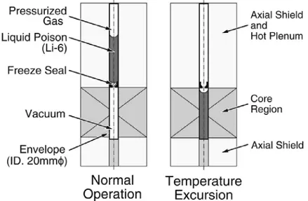
The concept of the Lithium Expansion Module (LEM) for inherent reactivity feedback is illustrated in Figure.3. The LEM consists of an envelope of refractory metal in which liquid poison of 95 per cent enriched 6Li is enclosed. 6Li placed in the positive void region of the core would result in negative reactivity insertion because neutron absorption by 6Li dominates over scattering.
Figure 3. LEM concept
Lithium-6 is suspended in the upper part of the envelope by surface tension exerted on the gas–liquid interface. The LEM is actuated by the volume expansion of 6Li itself. If the core
outlet temperature increases, the gas–liquid interface goes down and negative reactivity insertion can be achieved.
Accordingly, it is effective to mitigate the anticipated transient without scram. The gas–liquid interface in the nominal operation is placed at the active core top. If the core outlet temperature decreases, the gas–liquid interface increases and no positive reactivity insertion is expected. Drawbacks related to this system concern the untested reliability and safety concerns as the boundary failures and the lithium hazards, including the chemical reactions. Boundary failures could result in gas release within the core with insertion of positive reactivity, depending on the position of LEM. Another issue pertains to the stability of the gas-liquid interface: in fact if the buoyancy force exceeds the surface tension, the gas–liquid interface will be broken. The critical diameter of the LEM envelope is determined by the balance between the surface tension, which is dependent on the temperature, and buoyancy force.
Lithium reacts not only with oxygen, like sodium, but also with nitrogen, so that to avoid lithium fires it is necessary to utilize other gases, as helium. In addition there is the risk of beryllium formation due to lithium absorptions of neutrons.
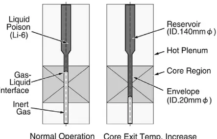
Lithium injection module
In the recent years LIM innovative system has been proposed for the RAPID fast reactor concept in Japan. The concept of the Lithium Injection Module (LIM) for inherent ultimate shutdown is illustrated in Figure 4. The LIM also comprises an envelope in which 95 per cent enriched 6Li is enclosed. If the core outlet temperature exceeds the melting point of the freeze seal, 6Li is injected by a pneumatic mechanism from the upper into the lower region to achieve negative reactivity insertion. In this way the reactor is automatically brought into a permanently subcritical state and temperatures are kept well below the boiling point of lithium (1330 °C).
The time required for reactivity insertion of the LIM is 0.24 s, which is shorter than the time required for free drop of conventional scram rods (i.e. as much as 2 s).
Similarly to LEMs, LIMs assure sufficient negative reactivity feedback in unprotected transients, like UTOP and ULOF. The role of the LIM is to provide variety and redundancy of inherent safety in unprotected transients. Either LEMs or LIMs can meet such transients independently.
The injection temperature, which depends on the requirements of the core design, can be selected from several candidate materials of the freeze seal support. Thus freeze seal design is the key issue to ensuring accurate injection temperature over the design lifetime. The freeze seal segment consisting of CuNi alloy (trade name L-30) is to assure an injection temperature of 1240 °C. When adopting Al for the freeze seal, LIM injection would be performed at 660 °C. This innovative concept has undergone some experimental verifications of its performance, as injection tests on the LIM specimen at quasi-steady-state heat up, to demonstrate the freeze seal function. LIM freeze seal function has been confirmed by experiments including long life behaviour, as reported.
Main issues concern firstly the integrity of the LIM envelope that must be assured during reactor operation; in addition the irradiation behaviour of the freeze seal must be assessed, especially as regards the time span of fuel design life or core design life. Also the freeze seal performance is to be assessed in terms of prompt response to abnormal events leading to excessive core outlet temperatures. The use of lithium poses the same challenges with respect to the LEM concept.
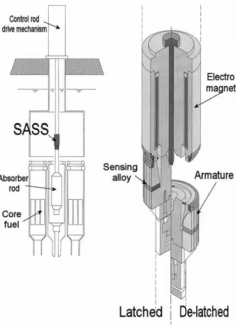
Curie point latches
The Curie point electromagnet SASS consists of an electromagnet and an armature that are parts of its magnetic circuit containing a temperature-sensing alloy as shown in Figure 5. The magnetic force is abruptly lost when the alloy is heated up to its Curie point by the heated coolant from the core. Then the armature de-latches at the detach surface and drop together with the control rod into the reactor core. The Curie point SASS is a simple structure and has flexibility of the detaching position.
The representative of this system is SASS designed for the commercial fast reactor Demonstration Fast Breeder Reactor (DFBR) design study in Japan.
As in the previous case the system performance is to be assessed in terms of system prompt response to abnormal events leading to excessive core outlet temperatures,