Setecec, p. 1, 2012.
© Springer-Verlag Berlin Heidelberg 2011
A Practical Setup for Projection-based Augmented Maps
Filippo Bergamasco, Andrea Albarelli and Andrea TorselloDipartimento di Scienze Ambientali, Informatica e Statistica Università Ca’ Foscari di Venezia
Abstract. Projected Augmented Reality is a human-computer interaction
scena-rio where synthetic data, rather than being rendered on a display, are directly projected on the real world. Differently from screen-based approaches, that only require to know the pose of the camera with respect to the world, this setup poses the additional hurdle of knowing the relative pose between capturing and projecting devices. In this paper we propose a thorough solution that addresses both camera and projector calibration using a simple fiducial marker design. Specifically, we introduce a novel Augmented Maps setup where the user can explore geographically located information by moving a physical inspection tool over a printed map. Since such tool presents both a projection surface and a 3D-localizable marker, it can be used to display suitable information about the area that it covers. The proposed setup has been evaluated in terms of accuracy of the calibration and of ease of use declared by the users.
Keywords: Augmented Reality; Camera-Projector Systems; Calibration;
Aug-mented Maps
1
Introduction
The landscape of Augmented Reality systems proposed in literature is very varied and includes a wide range of different techniques. However, most setups are built upon three fundamental blocks: a positioning system, a display device and an interaction model [1].
The positioning system is often composed of a camera and a set of artificial or natural markers. Within this kind of setup the camera is used to acquire images of the mark-ers and computer vision algorithms are applied to them in order to find the pose of the imaging system with respect to the world [2] [3] [4]. All these pose recovery tech-niques require the determination of a number of correspondence between features on the scene and their images on the projective plane. In principle such correspondences can be recovered from naturally occurring features in the image such as interesting point on a planar surface [5], ellipses [6], straight lines [7] or even the user’s hand [8]. In practice, for many real-world applications, this approach is not always feasible, since robust features cannot be guaranteed to exist in the scene, and even when found, their accuracy strongly depends on scene-dependant factor such as illumination, con-trast or texture. To overcome these limitations, a number of artificial markers have been proposed over the last two decades. The goal of a fiducial marker design is to
introduce elements in the scene that are easy to detect and that can be located with good accuracy. Some approaches rely on the invariance of conics such as concentric discs [9] or regularly arranged circles [10] [11]. In fact, under a generic projective transformation, circles always appear as ellipses, that are shapes easy to find and whose centers can be inferred with high precision. Other approaches exploit the inva-riance of straight lines, usually arranged to build high-contrast square boxes, that can be recognized by means of image-based recognition [12] or decoding of the marker content [13].
The display device can be a screen, a head-mounted display, a portable device or even the real world, as some approaches adopt projection techniques to overlay information to real objects. Head-mounted displays can be used in conjunction with front cameras and trackers to offer an immersive experience to the user. By contrast, augmented environments can be displayed and navigated through desktop interfaces. Both ap-proaches have been shown to have advantages and disadvantages [14]. A popular intermediate solution between dedicated helmets and desktop navigation is represented by adopting portable devices such as mobile phones or tablet [12]. This latter approach is very practical since these devices are becoming ubiquitous and come equipped with high resolution cameras and screens.
Finally, interaction models include both traditional computer-based controls and body mounted sensors or even more complex physical haptics. Recent approaches include wearable gestural interfaces [15], tangible interfaces [16] and virtual mirrors [17]. In this paper we develop a setup for projection-based augmented maps that is based on a projective-invariant marker design which is used for four different purposes: the detection of the physical controller moved by the user, the localization in the 3D space of the display surface and, finally, the calibration of both the camera and the projector. In the following sections the system will be described in depth and the cali-bration procedure will be defined. The concept of augmented maps is not new per se, in fact this concept has already been explored using both head-mounted [18] and pro-jected displays [19]. Nevertheless, in the following sections we will introduce two novel contributions: an interaction model that involves the use of the exploration de-vice in the entire 3D space, and a camera-projector calibration pipeline that does not require initial guesses about intrinsic or extrinsic parameters, is semi-automated and very simple to implement.
2
Description of the System and User Interaction
A schematic representation of the setup can be seen in Fig. 1. From a technical stand-point the system is made up of a digital projector, a camera, a board where the map of interest is physically printed and a navigation device. The projector and the camera are rigidly mounted on a stand and are both oriented toward the table so that their frustum covers the entire area of interest. A calibration procedure (described in Sec. 4) is performed to obtain an accurate estimate of the intrinsic parameters for both devices (i.e. their focal length, principal point and radial distortion) and of their rela-tive orientation. The navigation device is basically a rectangular rigid board that
exhibits a white matte projection area and a frame that contains the fiducial marker to track (described in Sec. 3). This marker is continuously captured by the camera and its location in 3D space is estimated at each frame. Since the rigid transform that binds the camera to the projector is known and the projector frustum itself corres-ponds to the map area, all the parameters are available to reconstruct the position of the navigation device with respect to the map and to the projector and thus to display on the matte area some contextual data related to the location observed by the user. The geometrical relation between the projector and the navigation device is used to rectify the displayed image so that it appears exactly as if it was formed on the screen of an active device. By printing different markers, more than one navigation device can be used simultaneously, thus allowing many users to operate on the table. Finally, since the marker position is determined in 3D, additional functions such as zooming can be controlled through the vertical position of the device.
In Fig. 2 an actual implementation of the setup (described in Sec. 5) and the zooming effect attainable are shown.
Fig. 2. Actual setup and examples of usage by moving the controller in space. Fig. 1. Representation of the proposed setup
3
Fiducial Markers Design
For our setup we decided to use a novel type of fiducial markers described in [20] that exploit projective invariants to allow simple, fast and accurate pose estimation.
These tags are composed by a series of 12 dots arranged in a rectangle (Fig. 3), with 2 dots per side and corner dots shared between each side. The relative distance of each dot is crafted to exploit the cross-ratio invariance among projective transforma-tions. Given a constant α, a whole class of tags can be generated by ensuring that
kh jh ik
ij cr cr cr
cr . The well known instability of cross-ratio with respect to noise is partially compensated by the internal redundancy of their design and allow us to use up to about ten tags simultaneously in a practical scenario without sacrifice detection reliability. On the other hand, unlike other marker types available in litera-ture, the ellipse-based design ensure great accuracy in pose estimation and the usage of projective invariants remove any rectification step usually involved in the recogni-tion stage.
Pi-Tags exhibits several features particularly attractive for our purposes:
1. The marker interior is empty and so is the ideal choice to be used as a virtual screen to project multimedia content to the user.
2. The aspect ratio of the tag can be freely modified as it doesn’t influence the cross-ratio constraint. This is particularly useful if the marker is used as a frame around a picture or other type of artistic content that cannot be modified.
3. The good pose estimation accuracy allows a steady projection without flickering or similar artifacts that may heavily hinder the user experience.
4. The tradeoff between the size of the dots and their relative distance from the cam-era can be adjusted to fit the individual application needing. If the hardware setup requires a camera far away and/or with low resolution the dot size can be increased without any modification even on tag descriptors.
5. Marker design is simple and not invasive against the content presented to the user. 6. They can be effectively used also for calibration purposes, as explained in Sec. 4.
4
Calibration Procedure
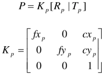
To project multimedia content onto the physical marker plane we need to estimate the projector projection matrix P:
]
|
[
p p pR
T
K
P
Where:
1
0
0
0
0
p p p p pfy
cy
cx
fx
K
are projector intrinsic parameters, and [Rp|Tp] is the relative pose of the projector with
respect to the marker, or the extrinsic parameters. Once the matrix P has been esti-mated, a 3d point pw lying on the marker plane can be projected by transforming its 3d
coordinates to [ xw yw 0 ]T projector image-space pixel coordinates [ up vp ]T with the
following equation: w w w p p
Pp
y
x
P
v
u
1
0
1
Unfortunately, the projector cannot estimate the relative pose [Rp|Tp] by itself because
it is a pure output device. To provide that data, a camera is placed nearby ensuring that the viewing frustum of the projector is contained in the viewing frustum of the camera. As long as the relative position between the camera and projector remains unchanged, [Rp|Tp] can be estimated in terms of the camera pose [Rc|Tc] obtained via
fiducial markers in the following way:
1 0 1 0 1 0 c c cp cp p p T R T R T R
Where [Rcp|Tcp] is the rigid motion that maps from camera coordinate system to
projector coordinate system. The first step of the calibration procedure is the estima-tion of the camera intrinsic parameters and radial distorestima-tion. This step is achieved by creating a map between a large set of known 3d points, viewed from different posi-tions, and their respective projection onto camera image plane. To build this mapping we created a planar calibration target with 6 pi-tags disposed at known position (Fig. 3, right). This is done in order to capture a larger number of points for each shot, but, in principle, even a single marker could be used. The detection code of Pi-Tags allows to identify each dot on the calibration target and establish the correspondence between the 3d position of the dot (defined in the calibration target model) and its 2d projec-tion on camera image (computed by the detector).
After the creation of this mapping, a non-linear optimization algorithm is used via OpenCV calibrateCamera function [21] to obtain the camera intrinsics:
1 0 0 0 0 c c c c c fy cy cx fx K
The estimation of Kp and [Rcp|Tcp] is also performed from a set of known 3d-2d
cor-respondences but, because the projector cannot “see” the markers and retrieve 3d positions of dots in the calibration target, an alternative method is used to provide this mapping.
A big square Pi-Tag marker is printed on a planar surface and placed under the camera/projector frustum (Fig. 4). Once the tag is placed, a snapshot is taken by the camera and used for background subtraction. This allow us to project a dot (of simi-lar size of marker’s ones) with the projector by randomizing its 2d position in projec-tor plane, and detect its center with no ambiguity using the camera. If the camera detects that the projected dot lies inside the marker, the 3d position of the dot can be recovered because the marker plane position is known with respect to the camera via Pi-Tag pose estimator.
The whole process can be summarized as follows:
1. A planar surface with a Pi-Tag marker is placed randomly under camera/projector frustum, and a snapshot is taken;
2. A dot pp = [ up vp ]T is projected randomly by the projector. Via background
sub-traction the camera can identify the dot projected and determine its 2d position pc =
[ uc vc ]T in the camera image plane;
3. If the 2d position of the dot lies inside the marker, its 3d position pw = [ xw yw zw ]T
(in camera world) can be recovered as the intersection of the line from the camera center of projection 0 and the point T
c c c c c c fy cy v fx cx u
1 and the marker plane, computed using Pi-Tag pose estimator;
4. Steps 2 and 3 are repeated to collect hundreds of 3d-2d correspondences (pw,pp)
from this point of view;
5. Steps 1 to 4 are repeated to collect correspondences between different point of views. For our purposes, about half a dozen of different point of views is usually enough;
6. OpenCV calibrateCamera function is used to estimate Kp and the rigid motion
[Rcpi|Tcpi] between the randomly-projected 3d points in camera world from each
point of view and the projector. As final [Rcp|Tcp] we simply choose the rigid
mo-tion with respect to the first point of view [Rcp0|Tcp0] but different strategies may be
used.
Only the first step requires human intervention instead of points 2 and 3 that needs to be iterated thoroughly to collect a large set of correspondences.
Even if the process is automatic, steps 2 and 3 may require a very long time depend-ing by the probability that the random dot pp will lie inside the marker at each
itera-tion. To speed up the calibration procedure, for each point of view, after at least 4 projections lying inside the marker, an homography H can be computed that maps points from camera image plane to projector image plane. With the homography H, each point pp can be randomized directly lying inside the marker thus eliminating the
waste of time required to guess the correct set of positions.
In our setup we are able to collect more than 10 correspondences per second, for an average calibration time of less than 15 minutes.
5
Experimental Evaluation
The described setup has been implemented in our laboratory for experimental purpos-es. To this end we chose to use as the base map the well-known lithography made by Jacopo De’ Barberi in 1500 that represents an aerial view of the island of Venice [22] (see Fig. 2). The data projected over this aerial view was a current satellite map of Venice obtained by downloading single tiles from Google Maps and by composing them in a complete view subject to a slight geometrical deformation. This transforma-tion was needed to correctly overlay the data to the partially incorrect projective view provided by De’ Barberi. The user interaction happens by moving an inspection tool printed on a PVC sheet. The user can move the tool over the original lithography and see through the inspection device the current photorealistic appearance of the same area together with optional toponomastic. By moving the target vertically the view is zoomed in a similar fashion to what would happen using a magnifying glass.
5.1 Calibration accuracy
To create a quantitative evaluation of calibration accuracy obtainable with our setup we crafted a target with an embedded square figure surrounded by a 1-mm-spaced line grid (Fig. 5, right). Specifically, a projector was placed 1500 mm above the table with a one-megapixel camera positioned 50mm on the right. A 240x240 mm calibra-tion target was used. We tested the calibracalibra-tion procedure varying the number of dots
(3d-2d correspondences) and point of views (positions of planar target with respect to the camera).
After each calibration procedure, a virtual square is projected onto the real square printed on the target to measure the displacement of each side with respect to the model and evaluate the maximum error in millimeters. The measure is repeated for different positions inside the projector frustum to compute the average error and its standard deviation. As shown in Fig. 5 (left), the error decreases as the number of dot rises, being significantly lower when 6 points of view are presented. For any practical purposes, a calibration performed with a hundred of dots divided into 6 points of view is sufficient to obtain an average error less than 1 millimeter, getting an almost perfect projection on the inspection tool.
5.2 User experience
Our augmented map of Venice was presented in the Ca’Foscari exhibition hall to about 50 individuals to analyze the overall user satisfaction. About all users were able to successfully interact with the system without assistance nor previously-given in-structions. The overall satisfaction level was pretty high, after a period of testing vast majority of candidates were fascinated by the ease of use and novelty of the interac-tion model.
Two main drawbacks were reported by the users. The first was the slight latency de-tected especially while the inspection tool is moved quickly on the map. This is due to the fact that the internal buffer of the projector introduces an unavoidable latency from the time since a frame is sent to the projector and the time in which the frame is actually projected. The second drawback is that the augmented map cannot be pro-jected successfully if the dots on the inspection tool are covered. In our setup this problem is partially reduced with a software-based tracker that interpolates the pre-dicted tool position in between the frames where it is unseen. To address this issue more in depth, as a future work, we will experiment new types of fiducial markers resilient to severe occlusions.
F ig. 5. Accuracy of the calibration with respect to the number of dots projected and the
6
Conclusions
We described a practical setup for projection-based augmented maps, based on a nov-el type of fiducial markers that allows to project multimedia content in their interior without sacrificing detection reliability nor pose estimation accuracy. The system is used to project virtual contents on a physical inspection tool depending on its position above a printed map, making it an effective augmented reality device for museum exhibitions, interactive learning etc. Since tracking can be easily performed in the whole 3D space, zooming or other inspection function can be implemented by taking advantage of vertical movements.
We also outlined a semi-automatic calibration procedure that uses the same fidu-cial marker components to precisely estimate the geometric relations between the camera and projector to allow an accurate display of contents regardless of the actual pose of the inspection tool, as presented in the experimental section.
References
1. Feng, Z., Been-Lirn Duh, H., Billinghurst, M.: Trends in augmented reality tracking, interaction and display: A review of ten years of ISMAR. In : Proceedings of the 7th IEEE/ACM International Symposium on Mixed and Augmented Reality, Washington, DC, USA, pp.193--202 (2008)
2. Lowe, D.: Fitting Parameterized Three-Dimensional Models to Images. IEEE Trans. Pattern Anal. Mach. Intell. 13(5), 441--450 (1991)
3. Davis, L., DeMenthon, D.: Model-Based Object Pose in 25 Lines of Code. International Journal of Computer Vision 15, 123--141 (1995)
4. Lan, L., Zhong-Dan: Linear N-Point Camera Pose Determination. IEEE Trans. Pattern Anal. Mach. Intell. 21(8), 774-780 (1999)
5. Simon, G., Fitzgibbon, A., Zisserman, A.: Markerless Tracking using Planar Structures in the Scene. In : Proc. International Symposium on Augmented Reality, pp.120--128 (2000)
6. Qian, C., Haiyuan, W., Toshikazu, W.: Camera Calibration with Two Arbitrary Coplanar Circles. In : European Conference on Computer Vision (ECCV 2004), pp.521--532 (2004)
7. Elqursh, A., Egammal, A.: Line-based relative pose estimation. In : IEEE Conference on Computer Vision and Pattern Recognition (CVPR 2011), Providence, RI, pp.3049--3056 (2011)
8. Lee, T., Höllerer, T.: Multithreaded Hybrid Feature Tracking for Markerless Augmented Reality. IEEE Transactions on Visualization and Computer Graphics 15(3), 355--368
9. Gartell, L., Hoff, E., Sklair, C.: Robust image features: Concentric contrasting circles and their image extraction. In : Proc. of Cooperative Intelligent Robotics in Space, Washington, USA (1991)
10. Cho, Y., Lee, J., Neumann, U.: A multi-ring color fiducial system and a rule-based detection method for scalable fiducial-tracking augmented reality. In : International Workshop on Augmented Reality (1998)
11. Claus, D., Fitzgibbon, A.: Reliable automatic calibration of a marker-based position tracking system. In : IEEE workshop on Applications of Computer Vision (2005)
12. Wagner, D., Reitmayr, G., Mulloni, A., Drummond, T., Schmalstieg, D.: Real time detection and tracking for augmented reality on mobile phones. IEEE Transactions on Visualization and Computer Graphics 99 (2010)
13. Fiala, M.: Designing highly reliable fiducial markers. IEEE Trans. Pattern Anal. Mach. Intell. 22, 1066-1077 (2010)
14. Sousa Santos, B., Dias, P., Pimentel, A., Baggerman, J.-W., Ferreira, C., Silva, S., Madeira, J.: Head-mounted display versus desktop for 3D navigation in virtual reality: a user study. Multimedia Tools and Applications 41(1), 161-181 (2009) 15. Mistry, P., Maes, P., Chang, L.: WUW - wear Ur world: a wearable gestural
interface. In : Proceedings of the 27th international conference on Human factors in computing systems, Boston, MA, USA, pp.4111--4116 (2009)
16. Pittarello, F., Stecca, R.: Mapping Physical Objects to Digital Functions: A Tangible Interface for Querying and Navigating a Multimedia Database. In : 22nd International Workshop on Database and Expert Systems Applications, Washington, DC, USA, pp.134-138 (2011)
17. Bichlmeier, C., Heining, S. M., Feuerstein, M., Navab, N.: IEEE Transactions on Medical Imaging 28(9), 1498-1510 (The Virtual Mirror: A New Interaction Paradigm for Augmented Reality Environments)
18. Bobrich, J., Otto, S.: Augmented Maps. Geospatial Theory, Processing and Applications 34(4) (2002)
19. Reitmayr, G., Eade, E., Drummond, T.: Localisation and Interaction for Augmented Maps. In : IEEE International Symposium on Mixed and Augmented Reality, Vienna, Austria, pp.120-129 (2005)
20. Bergamasco, F., Albarelli, A., Torsello, A.: Image-Space Marker Detection and Recognition Using Projective Invariants. In : 3D Imaging, Modeling, Processing, Visualization and Transmission, International Conference on, Hangzhou, pp.381-388 (2011)
21. Bradski, A., Kaehler, A.: Learning OpenCV: Computer Vision with the OpenCV Library. O'Reilly Media Inc. (2008)