4
th
IEEE International
Workshop on Advances in
Sensors and Interfaces
28-29 June 2011
Borgo Egnazia
Savelletri di Fasano, (Brindisi), Italy
II
Proceedings of the
4
th
IEEE International
Workshop on Advances in
Sensors and Interfaces
June 28-29, 2011
Borgo Egnazia
III
IV
Proceedings
4
th
IEEE International Workshop on Advances
in Sensors and Interfaces
June 28-29, 2011
Borgo Egnazia
V
Copyright ©2011 by the Institute of Electrical and Electronics Engineeers, Inc.
All rights reserved
Copyright and Reprint Permission: Abstracting is permitted with credit to the source. Libraries are
permitted to photocopy beyond the limit of U.S. copyright law for private use of patrons those articles in
this volume that carry a code at the bottom of the first page, provided that the per-copy fee indicated in
the code is paid through Copyright Clearance Center, 222 Rosewood Drive, Danvers, MA 01923.
For other copying, reprint, or republication permission, write to IEEE Copyrights Manager, IEEE Service
Center, 445 Hoes Lane, Piscataway, NJ 08854. All rights reserved.
IEEE Catalog Number: CFP11IWI-USB
ISBN: 978-1-4577-0622-6
Additional copies of this publication are available from: Curran Associates, Inc. 57 Morehouse Lane, Red
Hock, NY 12571 USA. Phone: (845) 758-0400, Fax: (845) 758-2633; E-mail: [email protected].
©2011 IEEE. Personal use of this material is permitted. However, permission to reprint/republish this
material for advertising or promotional purposes or for creating new collective works for resale or
redistribution to servers or lists, or to reuse any copyrighted component of this work in other works must
be obtained from the IEEE.
VI
Contents
Foreword
XI
Organizing Committee
XII
Session I: Advances in Sensors and Interfaces
1
1,000 Electronic Devices per Living Person: Dream or Nightmare?
A. Sangiovanni Vincentelli
2
Wearable sensor systems for healthcare and lifestyle
J. Penders
3
Session II: MEMS
4
Droplet Transport on Microstructured Superhydrophobic Surfaces
K. F. Böhringer
5
An Embedded System for Real Time Vibration Analysis
G. Merendino, A. Pieracci, M. Lanzoni, B. Riccò
6
A Poly-Si Based 2-Axis Differential Capacitive-Sensing Accelerometer
C.-K. Chan, Y.-C. Huang, M. Wu, W. Fang
12
Study of Built-in Stress Distribution in AlGaN/GaN/AlN Heterostructure Based
Cantilevers for Mechanical Sensing in Harsh Environments Sessione III
S. Vittoz, L. Rufer, G. Rehder,
R. Srnanek, J. Kovac
17
Session III: Novel Technology for Sensor
21
Combination of 2D and 3D vision systems into robotic cells for improved flexibility
and performance
G. Sansoni, P. Bellandi, F. Docchio
22
Electrons: Do We Really Need Them?
E. Charbon
31
Session IV: Advances in high energy electronics
32
3D vertical integration technologies for advanced semiconductor radiation sensors
and readout electronics
V. Re
33
Diamond particle detectors for high energy physics
G. Chiodini
VII
A Cluster Timing Algorithm for Drift Chambers Readout Electronics
L. Cappelli, P. Creti, F. Grancagnolo
43
Design and simulation of a 64 channel, high voltage analog interface for
stimulation and acquisition of neural signals
L. Abbati, C.L. Frewin, P. Placidi, S.E. Saddow, A. Scorzoni
45
Bend sensor arrays for hand movement tracking in biomedical systems
G. Saggio
51
Session V: Integrated Systems of Sensors
55
Nanosystems: sensors and electronics for rational health monitoring
G. De Micheli
56
High speed sensing using ion sensitive field effect transistors
D. R. S. Cumming, P. N. Shields, M. S. Piechocinski, B. Nemeth
57
Session VI: Electronics for Smart Sensors
60
Input Characteristics of a Chopped Multi-Path Current Feedback Instrumentation
Amplifier
Q. Fan, J. Huijsing, K. Makinwa
61
Ramp Calibration of Temperature Sensors
K. Souri, K. Makinwa
67
Low Power Smart Sensor for Accurate Temperature Measurements
D. De Venuto, E. Stikvoort
71
High Dynamic Range Current-to-Digital Electronics for Lab-on-chip Applications
A. Nascetti, M. Truglio, P. Valerio, D. Caputo, G. de Cesare
77
NBTI Resistant SRAM Design
F.Ahmed, L. Milor
82
Session VII: Bio-chemical sensor
88
Membrane protein biosensor arrays on CMOS
A. J. Mason
89
Comparing the enhanced sensing interfaces of differently oriented carbon
nanotubes onto silicon for bio-chip applications
I. Taurino, S.Carrara, M. Giorcelli, A.Tagliaferro, G. De Micheli
VIII
Surface chemical functionalization of single walled carbon nanotubes by mutated
Bacteriorhodopsin towards sensing applications
C. Ingrosso, G. Bianco, P. Lopalco, M. L. Curri, A. Agostiano, A. Corcelli, G. Bruno,
M. Striccoli, P. Siciliano
94
Purification of substances contaminated with mycotoxins using functionalysed
microparticles
A.V. Nabok, M.K. Mustafa, V. Erokhin, S. Erokhina, A. Szekacs
99
Session VIII: Ambient Living Sensing System
103
A context-aware smart seat
M. Benocci, E. Farella, L. Benini
104
Topological and Volumetric Posture Recognition with Active Vision Sensor in AAL
Contexts
A. Leone, G. Diraco, P. Siciliano
110
Design, Characterization and Management of a Wireless Sensor Network for Smart
Gas Monitoring
V. Jelicic, M. Magno, G. Paci, D. Brunelli, L. Benini
115
Gas microsensor array for Breath Analysis: an explorative study of smoking status
risk
S. Capone, L. Mazzotta, L. Francioso, M. Epifani, P. Siciliano
121
Core-Shell Gold Nanoparticles and Gold-Decorated Metal Oxides for Gas Sensing
Applications
A. Afzal, A. Monopoli, C. Di Franco, N. Ditaranto, B. Mariano, N. Cioffi, A. Nacci,
G. Scamarcio, L. Torsi
125
Generation Of Energetic Compounds For Calibration Of Explosives Vapors
Detectors
C. Frenois, T. Caron, M. Bouhadid, F. Veignal, N. Eloy, P. Montmeat, C. Barthet,
L. Hairault, E. Pasquinet
129
A portable biosensor system for bacterial concentration measurements in cow’s
raw milk
M. Grossi, M. Lanzoni, A.Pompei, R. Lazzarini, D. Matteuzzi, B. Riccò
132
Posters
138
Architecture and Front-End for in-vivo Blood Glucose Sensor based on Impedance
Spectroscopy
G. Gelao, R. Marani, F. De Leonardis, V. M.N. Passaro, A. G. Perri
IX
Design of Optimized SOI Slot Waveguides for Homogeneous Optical Sensing in
Near Infrared
F. De Leonardis, G. Giannoccaro, B. Troìa, V. M. N. Passaro, A. G. Perri
142
Manganese doped Znic Oxide thin film Hydrogen gas sensor at reduced operating
temperature.
A. Chatterjee, P. Bhattacharjee, P. Kumbakar, N. Kumar Roy
148
An in-line contact configuration for the Hall sensor device
P. Wipatawit, S. Wangtong, O. Trithaveesak, C. Hruanun, A. Poyai
153
A Sensor Interface Based on Sparse NMF for Piano Musical Transcription
G. Costantini, M. Todisco, G. Saggio
157
Surface Studies Of A Biomaterial For The Development Of A Biosensor For The
Detection Of Trace Metals
J. O. Okonkwo, C. Zvinowanda, M. Sekhula, N. Mahlala
162
Analysing manufacturing imperfections in a spherical vibratory gyroscope
S. V. Joubert, M. Y. Shatalov, C. E. Coetzee
165
Beam test results of new pixel sensors bump-bonded to the ALICE pixel front-end
chip
R. Santoro
171
Robust Data Collection and Transfer Framework for a Distributed SRAM Based
Neutron Sensor
L. Dilillo, A. Bosio, P. Rech, P. Girard, F. Wrobel, F. Saigné
176
A Novel Technique to Examine the Optical Properties and Stress of Thin Films
C.-Y. Han, F.-C. Huang, J.-H. Ye, H.-F. Chen
181
WEGES: A Wireless Environmental Gases Electronic Sensor
V. Di Lecce, R. Dario, A. Amato, J. Uva, A. Galeone
186
A Data Glove Based Sensor Interface to Expressively Control Musical Processes
G. Saggio, F. Giannini, M. Todisco, G. Costantini
192
Fabrication at Wafer Level of Micromachined Gas Sensors Based on Sno2 Nanorods
Deposited by PECVD and Gas Sensing Characteristics
A. Forleo, L. Francioso, S. Capone, F. Casino, P. Siciliano, H. Huang, O.K. Tan
196
Phase Readout of Thermal Conductivity-Based Gas Sensors
C. van Vroonhoven, G. de Graaf, K. Makinwa
199
Sensors for monitoring water and oxygen in the VUV spectrometer of ALICE-HMPID
detector at CERN-LHC
A. Di Mauro, G. De Cataldo, A. Franco, M. Mastromarco, C. Pastore, I. Sgura
X
Modeling of the Photo-Response of a Smart Thin Layer Chromatography System
D. Caputo, G. de Cesare, M. Nardini, A. Nascetti, R. Scipinotti
208
Design and Characterization of a 32-channel Front-end ASIC for Silicon
Photo-Multiplier Detectors
C. Marzocca, G. Matarrese and F. Corsi
212
XI
FOREWORD
Welcome to the fourth IEEE International Workshop on Advances in Sensors and Interfaces
(IWASI) in Savelletri di Fasano (Brindisi), Italy June 28 – 29, 2011.
The workshop is aiming at bringing the gap between sensor devices and their integration with
electronics by using newly developed technologies. IWASI provides a forum for the exchange of
new ideas and concepts. It spans a range from sensor applications, over biological and chemical
sensors as well as sensors for high-energy physics and sensor interfaces and networks.
Traditionally besides the workshop a vendor exhibition for electronic design and test is presenting
most recent products.
The technical program is organized into eight sessions covering
-
recent advances in sensors and interfaces
-
biosensor system design
-
IC design methodologies
-
wireless sensors
-
sensor technology
-
sensors for physics
-
sensors for chemical applications
As already in the previous years IWASI 2011 invited 10 outstanding and internationally renowned
key note speakers enhancing the workshop. From the submitted papers 21 regular papers and 19
posters were selected in a peer review and are presented to the participants.
Special focus of this year’s workshop will be:
o
MEMS
o
Novel Technology for Sensors
o
Advances in high Energy Electronics
o
3D-Integration,
o
Electronics for Smart Sensors
o
Bio-chemical sensors
o
Ambient Living Sensing Systems.
Over the past years this international workshop has developed to become a vital forum to
exchange new ideas, as well as to foster and initiate an international network of individuals either
collaborating in research or in business in the wide and important field of sensor applications. It
offered an event to get new contacts, to find complementary partners, but also to discuss on
solutions one came across during the daily business.
On behalf of the Steering Committee I therefore invite you to take full advantage of the
opportunities offered to you by IWASI 2011.
Enjoy the IWASI2011 event.
Daniela De Venuto
IWASI 2011 General Chair
Combination of 2D and 3D vision systems into robotic cells for
improved flexibility and performance
Giovanna Sansoni, Paolo Bellandi, Franco Docchio Laboratory of Optoelectronics, Department of Information Engineering
University of Brescia, Via Branze, 38 25123 Brescia Author e-mail: [email protected]
Abstract-In this paper we present the research activity carried out in the integration of 2D and 3D vision systems into robot cells, to improve their performance in typical pick and place operations. Two projects have been developed: the former is the combination of a 2D vision system based on two cameras with a two-robot cell. The latter consists of the integration of a laser slit - based optical head in a robot arm, for the 3D recognition of pose and orientation of objects, in view of bin picking applications.
Both projects were committed by DENSO EUROPE B. V. with the aim of improving the robots performances in terms of flexibility and robustness of operation.
Index Terms-2D vision, 3D vision, robotics, calibration
I. INTRODUCTION
The ability to perform complex tasks in semi-structured or even unstructured environments is strategic in industrial robot-based applications. In pick and place operations, for example, the possibility of recognizing and manipulating unorganized objects increases the efficiency of the production line, since both the time and the investments to adapt the line to the production of new series can be dramatically reduced. On the other hand, a robot arm is blind by nature, and inherently unable to adapt to varying scenarios. One of the strategies that can be successfully implemented to cope with these limitations is to combine vision to robot motion.
Vision sensors and image processing techniques have been consistently developed in recent years, for visual inspection and measurement applications. Typical fields are automatic manufacturing, product inspection, [[1][3]], non-destructive testing [4], and welding applications [5]. In the last decade, vision inspection systems have been considered as a valuable aid to add to robots the ability to detect the scene and to follow and adapt to scene variations.
Our Laboratory has been active for years in the study of both 2D and 3D vision systems [6][7][8]. Since 2008 we have been given the opportunity of applying our knowledge in the realms of robot applications. Two projects started in collaboration with DENSO EUROPE B.V.
The first project dealt with the integration of a 2D vision system in a DENSO robot cell for drink serving operations. The cell is called ‘Barman’. Two anthropomorphic robots were used to pick-up beer bottles from a conveyor, uncork them, and place them on a rotating table. The robots were programmed to perform a very limited set of actions, in a
static, highly controlled environment; for example, the bottle shape was pre-defined, and the position on the table of each bottle should correspond with the position of suitable bottle racks, rigidly embedded at the border of the table.
We were required to upgrade the system toward a ‘Smart
Barman’ version, characterized by improved flexibility with
respect to the original system. For example, the system should be able to serve beer of multiple brands, serve beer in glasses, and detect mis-positioned glasses. The underlying idea was to show the Barman functionalities at exhibitions, to demonstrate to potential costumers the advantages of using 2D vision in combination with robots, especially in terms of flexibility and robustness.
The second project focused on the integration of a 3D vision system for flexible bin picking applications. The ultimate goal was to estimate both position and orientation of unorganized objects in the working area, for optimized robot gripping. In this case, a single DENSO robot has been equipped with a laser slit, and by means of a novel combination of 2D and 3D vision algorithms, it has been possible to recognize the scene, and to segment the acquired 3D point cloud into the sub-parts corresponding to each object.
In this paper, the main characteristics of both systems are presented, especially with reference to the developed vision procedures and to their performances.
II. THE BARMAN SYSTEM
Fig. 1 shows the system layout. Two anthropomorphic, 6-DOF robots (DENSO VP-6242G), named Robot_1 and Robot_2, are the left and the right arm of the Barman respectively.
Fig. 1. The Barman layout.
22 978-1-4577-0624-0/11/$26.00 ©2011 IEEE
The end-effector of Robot_1 is a pneumatic gripper, for bottle picking and glass filling; the end-effector of Robot_2 is a plastic hand equipped with a bottle-opener. The robots are partially embedded into a ‘thorax-shaped’ case, on which the monitor is placed. Each robot is cabled to its own controller (model RC7M). The supervisor PC controls both robots through TCP/IP ports. The communication between SPC and robot controllers is implemented in the Orin2 platform [9]. The procedures developed to control the whole system are integrated into the VB.NET environment.
The vision system is composed of two CMOS digital USB 2.0 cameras (µEye 1540-M 1280x1024 pixel), both equipped with a 12mm focal length objective. They are called S_CAM and M_CAM respectively. As shown in Fig. 1, the former is mounted on the section above the monitor, at about 870 mm from the table. The latter is rigidly mounted at the end-effector of Robot_2. The whole vision software has been developed using the Halcon suite of programs (MVtech GmbH, Germany) [10].
The Auxiliary Subsystem includes the conveyor and the round table shown in Fig. 1. The conveyor delivers bottles to the Barman. The round table has a diameter of 1m, and can rotate around its center. In Fig. 1, a tray of dimension 220 mm by 180 mm is shown. The surface of the tray is black, and the inner surface of the glasses is white, for high contrast against the tray. Two table positions are allowed. The former, shown in Fig. 1, is called Front position, the latter is 180° rotated (Back position). When the table is in Front position, customers are expected to place glasses on the tray. When the table is in Back position, the Barman is expected to fill the glasses.
Fig. 2 shows a schematic diagram of the system workflow. It is based on the following tasks:
Calibration: the aim of this task is to define a Global
Reference System (GRS) common to both Robot_1 and S_CAM, in order to allow Robot_1 to correctly fill empty glasses viewed by S_CAM. A calibration master is used in both cases: when calibrating Robot_1, the positions of suitable points on the master are learned by using the teach pendant: the corresponding positions define axes X, Y, and Z of GRS reference.
Calibration of S_CAM is aimed at estimating the extrinsic parameters (pose and orientation of the camera with respect to GRS) as well as the intrinsic parameters (focal length and lens distortion) [11]. Camera calibration is accomplished by acquiring the calibration plate at five different positions in the FOV. The markers are segmented with respect to the background, and the coordinates of the center of each marker are detected (marker centroids). A specially designed Halcon operator calculates both the extrinsic and the intrinsic parameters of the camera, using a-priori knowledge of the geometry of the calibration plate and the measured values of the coordinates of the centroids [12].
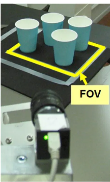
Waiting for glasses: in this task, the table is in the Front
position, and M_CAM is positioned as in Fig. 3. The ‘Tray_Monitor’ vision procedure detects if there are glasses on the tray. Customers can place and remove them from the tray; they can even orient them in incorrect positions (for
example, glasses very close to each other, or glasses turned upside down).
Fig. 2. The Barman system workflow.
The Tray_Monitor procedure is able to detect all these situations, and to discriminate among glasses that can be filled and glasses that must not be considered for subsequent operations.
Fig. 3. Position of M_CAM when waiting for glasses.
When a predefined number K of glasses is detected, the table is rotated toward the Back position. Here, the position of
each glass is estimated in GRS coordinates: the ‘Locate_Glasses’ vision procedure carries out this task.
Waiting for bottles: In this task, the system waits for beer
bottles on the conveyor. M_CAM is positioned as shown in Fig. 4: either different beer brands, or bottles with other drinks, or else unknown objects (i.e., objects that are not bottles) can be placed on the conveyor. Customers can position a single object, or arrange a row of objects.
All these situations are recognized by the ‘Object_Detection’ vision procedure. Whenever a beer bottle is detected, its coordinates are computed for subsequent picking; in case the object on the conveyor is not a beer bottle, the Object_Detection procedure estimates its dimension, for subsequent disposal.
Serving beer: the aim of this task is to uncork the bottle
and to fill the beer into the glasses. The information on the position of the glasses is given by the ‘Locate_Glasses’ procedure. The system is able to manage a number of different situations. For example, it recognizes if the bottle has been used to fill glasses before, and in this case it does not uncork it. It also keeps track of how many glasses can be filled, depending on the quantity of the beer still in the bottle; when the bottle is empty, it places it on the table, turns it, and serves beers. Object_Picking, Bottle_Uncorking, and Glass_Filling procedures carry out the above mentioned tasks.
Fig. 4. Position of M_CAM while waiting for bottles.
A. Vision procedures
The core of the system is represented by the vision procedures presented in this section.
Tray_Monitor_Procedure
In order to perform the Tray Monitor procedure, Robot_1 is positioned as shown in Fig. 1. M_CAM continuously acquires the FOV and calculates the number N of glasses that are placed on the tray, inside the indicated area. A threshold value K is predefined for the minimum number of glasses that can be placed on the tray; when the condition “N equal to or greater than K” is detected, the acquisition stops. A Region of Interest (ROI) is superimposed to the image. This operation is performed to define the area of the image corresponding to the
FOV; all subsequent operations are performed exclusively in the ROI. The procedure is based on the following steps: • Image binarization: this step is carried out to detect the
‘candidate’ regions corresponding to the glasses.
• Erosion: this operation is very useful to detect the glasses even when they are very close to each other. It erodes the input region with a structuring element in a way that its boundary gets smoothed and connected regions may be split [13].
• Image segmentation: those regions defined by the erosion are segmented, so as each glass is assigned to a blob. • Area filtering: this procedure calculates the area of each
blob and thresholds it, to detect the presence of glasses oriented in an uncorrected way (for example, glasses turned upside down).
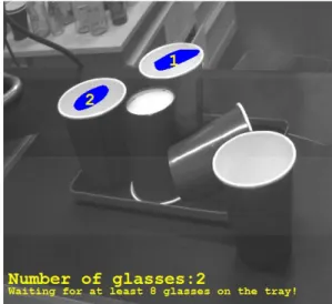
An example of the elaboration above described is shown in Fig. 5. The performance of this procedure is well evidenced in Fig. 6.
Fig. 5. Schematic representation of the sub-operations carried out by the Tray_Monitor procedure.
Fig. 6. Example of the Tray_Monitor performance in the presence of glasses positioned in uncorrected ways.
Locate_Glasses procedure
This procedure estimates the coordinates of the centers of mass of the elliptic areas corresponding to the glasses viewed by S_CAM, and maps them into real world coordinates, using the calibration parameters. The process is very similar to the one already developed in “Tray_Monitor” procedure, and is aimed at the recognition of the blobs that identify the glasses.
In addition to this, the estimation of the center of gravity of each blob is performed, to detect the position of each glass. Fig. 7.a shows the steps of the elaboration, while Fig. 7.b presents the resulting detection.
(a)
(b)
Fig. 7. Locate_Glasses procedure. (a): schematic representation of the image elaboration steps; (b): result of the detection.: glasses are numbered and the
coordinated of their centers of gravity coordinates are visualized.
An example of the robustness of this procedure is presented in Fig. 8: in both images it is easy to observe that the procedure can recognize situations where glasses are mis-positioned.
Fig. 8. Robustness examples of the Locate_Glasses procedure. Neither glasses turned up side down, nor those positioned outside the tray are detected.
Object_Detection Procedure
This procedure recognizes and classifies the objects detected at the end of the conveyor. Template Matching is used: it is based on the correlation between a template and the image [15]. Suitable templates are defined in such a way that it is possible to recognize which brand of beer is on the conveyor, and to detect beer bottles with respect to other, unknown objects. An example of the performance of this procedure is presented in Fig. 9. The image in Fig. 9.a shows the definition of a template: only the silhouette of the bottle is taken, in order to make the detection independent from its orientation, as shown in Fig. 9.b.
(a)
(b )
Fig. 9. The Object_Detection procedure. (a): definition of one template; (b) detection of the bottle.
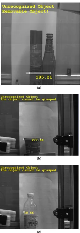
Another interesting characteristic of this procedure is the ability to estimate, in case the object on the conveyor is unknown, if the robot itself is able to pick it up and dispose of it, depending on its dimension. This task is accomplished by measuring the dimension of the object within a suitable ROI at the bottom of the image, and to check if it is compatible with the gripper dimension. Fig. 10 gives an idea of this task. In Fig. 10.a an unknown object is detected, and the system recognizes that it can be removed automatically (i.e. by means of the gripper). Note that the presence of an adjacent bottle does not prevent it from detecting this situation correctly. In
contrast, in Fig. 10.b, the situation where the operator intervention is mandatory is presented.
(a)
(b)
(c)
Fig. 10. Examples of the detection of unknown objects. (a): detection of an unknown object whose dimension are compatible with the gripper; (b) and (c):
detection of unknown objects that must be removed by the operator.
B. Whole system operation
The whole system operation is based on a suitable combination of vision with motion. Object_Picking, Bottle_Uncorking, and Glass_Filling procedures pick bottles up, uncork them (if necessary) and pour beer into the glasses. Motion is also necessary (i) to rotate the table, (ii) to place bottles on the conveyor (if all the glasses are full of beer and
the bottle is not empty), and (iii) to place empty bottles on the table for subsequent disposal.
The Barman operation is shown in a video at the laboratory website (www.optolab-bs.it). The system shows remarkable flexibility of operation and high robustness against variations of the scene under a number of aspects. In fact, it works well (i) independently from how the glasses are placed on the tray, (ii) the bottles are arranged on the conveyor, (iii) in the presence of blurred and noisy images, and (iv) under variations of the environmental illumination levels. The Barman system was used at the Automatica 2010 exhibit, as presented in Fig. 11.
Fig. 11. The Barman demonstrator at Automatica 2010.
III. THE ROBOSCAN SYSTEM
The Roboscan system has been developed as a robot-guide application that integrates 2D/3D vision sensors into a robot arm. The goal of the project was to obtain a system able to recognize the orientation of unknown objects in the working area, and to pick them up: to this aim, both vision and motion procedures are suitably combined to perform this task.
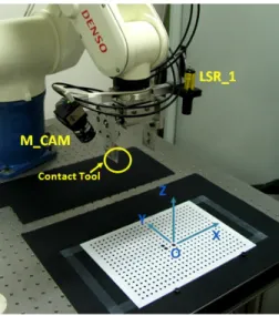
Fig. 12 shows the system layout. A DENSO robot model VS6556is used as the manipulator; the vision system is based on a video camera (IDS UI-1540SE), and on a laser projector (Lasiris 660nm, 10mW). The camera and the laser are denoted by M_CAM and LSR_1 in the figure. The laser projects onto the scene a laser slit, which is viewed at an angle by M_CAM. The camera-projector pair (denoted by TO_1) forms an optical 3D head based on laser triangulation. In addition, the camera is used per se, to acquire the 2D image of the field of view (FOV). With respect to other bin picking devices, the Roboscan system is able to recognize objects of different geometries and, for each of them, to compute their orientation. This behavior requires a high level of flexibility, and has been achieved by combining 2D vision with 3D vision.
To develop this application we worked in the LabView environment, and used the IMAQ libraries for vision (NI Inc., USA), together with the Robot Libraries (ImagingLab srl, Italy) to move the robot arm.
Fig. 13 shows the Roboscan workflow. It based on the following tasks:
Calibration: The aim of this task is to calibrate the robot,
the camera and optical head TO_1, in order to allow all these subsystems to share the same global reference system (GRS).
Fig. 12. The Roboscan system layout.
Fig. 13. The Roboscan system workflow.
The calibration master shown in Fig. 14 is used to perform all these operations. Specialized functions in the LabView environment allow us to acquire the master at different heights and to calculate the pose and the orientation of both M_CAM and TO_1 within GRS. In addition, they compensate for lens distortion [16]. As a result, the object points are estimated in the reference system of the robot.
2D elaboration: The aim of this task is to acquire the 2D
scene and to recognize the types of the objects in it.
Fig. 14. The master used to calibrate the system.
These operations are accomplished by means of blob analysis, image preprocessing and suitable geometrical pattern matching. A typical example of the elaboration is presented in Fig. 15. The acquired scene, shown in Fig. 15.a, is elaborated by means of blob analysis, which binarizes the image and determines the sub-area where objects are imaged. In Fig. 15.b, this sub-area is the one between the left and the right columns. Its knowledge greatly simplifies the subsequent 3D scanning, since it prevents the robot from scanning sub-areas where objects are absent.
(a)
(b)
(c)
Fig. 15. Steps of the elaboration during 2D acquisition. (a): image of the working area: (b): effect of blob analysis; (c): detection of the objects by
means of geometric template matching.
Object classification is carried out by means of geometric template matching. The technique is well known: it is based on the convolution between a template and the image: whenever the correlation score is higher than a predefined threshold, a positive matching is detected. Correspondingly, a number of parameters are calculated. Among them, we are interested into the position P(X,Y) of the center of the rectangle that frames each detected object, the corresponding area value, and the scale factor.
In order to obtain a template matching as effective as possible, suitable image preprocessing is performed before. It consists of brightness and contrast adjustment, gaussian blurring and laplacian edge detection. An example of the effect of both pre-processing and template matching is shown in Fig. 15.c, where each object is recognized and framed by a rectangle. It is worth noting that by defining a template for each object typology, it is possible to recognize the presence of different objects, and to estimate their position and orientation. This information is used in the 3D scanning task.
3d scanning: this task is naturally performed by optical
head TO_1. It scans the working area and outputs the corresponding point cloud. Since the system is calibrated, the point cloud is defined in the GRS system. An example of this process is presented in Fig. 16. The zoomed area in Fig. 16.a well highlights the detection of the image coordinates at each illuminated point. The plot in Fig. 16.b presents the corresponding 3D point cloud.
(a)
(b)
Fig. 16. 3D scanning task. (a): elaboration of the laser slit at the image plane; (b): corresponding 3D point cloud.
3D segmentation: this task is aimed at segmenting each
object of the whole 3D point cloud.
To efficiently perform this operation, the information coming from 2D template matching is used. In particular, the position of each rectangle yields the coordinates P(X,Y) of the framed object in the cloud, and the scale factor yields its position along the z coordinate (i.e. if it is above, at the same level of under other objects).
3D object fitting: each sub-cloud is elaborated to estimate
the orientation in GRS of the corresponding object. A surface fitting algorithm is used [17]. The algorithm fits the data points to a second-order polynomial, that fits planar, spherical, cylindrical and pyramidal surfaces. Object orientation is found by estimating the director cosines of the plane tangent to the fitted surface, in correspondence with position P(X,Y). Director cosines values are used to determine the orientation of the robot gripper.
Object Picking: object picking is straightforward: both the
position and the orientation of each object are known, and by means of simple motion commands, the robot can move the gripper accordingly to them, and picks objects up.
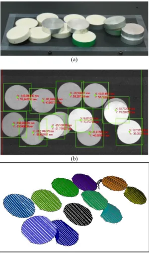
An example of the performance of this system is shown in Fig. 17, where a rather complex scene is considered.
(a)
(b)
(c)
Fig. 17. Example of 2D and 3D elaboration. (a): image of the objects in the work space; (b): detection of the position of each item by means of template
matching; (c): segmented 3D point cloud.
The objects in Fig. 17.a are of the same type, but they are quite a few, and randomly placed in the scene. In addition, some of them presents a very high reflectance, while some others are matted. The image in Fig. 17.b shows the effect of the 2D elaboration: the rectangles on the image frame all the objects that are viewed by M_CAM; each one has the coordinate P(X,Y) of its center assigned. It is worth noting that the template matching works quite well, since almost all the objects are detected. The two objects that are not framed are almost completely hidden by other items on them. They will be scanned in a subsequent step.
The performance of the 3D elaboration procedure is visible in Fig. 17.c: here, the white lines represent the whole 3D point cloud captured during the 3D acquisition step. A different solid color is assigned to each object, indicating that it corresponds to a segmented 3D sub-cloud.
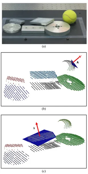
An example of how 3D object fitting works is presented in Fig. 18.
(a)
(b)
(c)
Fig. 18. Detection of objects of different shapes. (a): image of the scene in the working area; (b): estimation of the plane tangent to the ball in the upper-left
corner; (c): estimation of the tangent plane to the upper rectangle, in the center of the image.
In this experiment, the scene is characterized by different objects, partially overlapped, and with different reflectance and texture (Fig. 18.a).
The image in Fig. 18.b shows the segmented 3D point cloud, where the plane tangent to the ball in the upper right corner (plane A). Its orientation clearly shows that both the position of the ball, and the gripping direction (red arrow) has been correctly estimated.
In a similar way, the plane tangent to the rectangular object in the central part of the point cloud is shown in Fig. 18.c (plane B): it is inclined with respect to the orientation of the object beneath, as expected from the fact that in Fig. 18.a it is partially overlapped to the object at right (the one with circular shape).
IV. CONCLUSION
In this paper, the main features of two robotic cells that have been enhanced by integrating both 2D and 3D vision systems have been presented. The aim in both cases was to add flexibility and robustness to the robots, in picking applications. Both systems have been widely tested, and show significant improvements with respect to their performances before integrating the vision devices. Further developments deal with the integration of a 3D vision head based on fringe projection, to parallelize 3D acquisition and to speed up the robot operations.
ACKNOWLEDGMENT
The authors are grateful to Mr. Yosuke Sawada and to Dr. Gianluca Cavagnini for their continuous support during the development of these projects.
REFERENCES
[1] G. Rosati, G.Boschetti, A.Biondi, A.Rossi, “On-line dimensional measurement of small components on the eyeglasses assembly line,”
Opt Lasers Eng., vol. 47, pp. 320–328, 2009.
[2] Y. Xiong, F. Quek, “Machine Vision for 3D mechanical part recognition in intelligent manufacturing environments,” in Proc. 3rd International Workshop on Robotic Motion and Control (RoMo-Co’02), pp. 441-446,
2002.
[3] CS Lin, LW Lue, “An image system for fast positioning and accuracy inspection of ball grid array boards,” Microelectron. Reliab., vol 41, pp. 119-128, 2001.
[4] NDT, ASNT Level III Study Guide and Supplement on Visual and
Optical Testing, Columbus, OH, 2005.
[5] H. Fennander, V. Kyrki, A. Fellman, A. Salminen, H. Kalviainen, “Visual Measurement and tracking in laser hybrid welding,” Mach. Vis.
Appl., vol 20, pp. 103-118, 2009.
[6] G. Sansoni, A. Patrioli, F. Docchio, "OPL-3D: a novel, portable optical digitiser for fast acquisition of free-form surfaces," Rev. Scient. Instr., Vol. 74, pp. 2593-2603, 2003.
[7] G. Sansoni, F. Docchio, “In-field performance of an optical digitizer for the reverse engineering of free-form surfaces”, International Journal of
Advanced Manufacturing Technologies, vol. 26, pp. 1353-1361, 2005.
[8] G. Sansoni, F. Docchio, “Three-dimensional optical measurements and reverse engineering for automotive applications,” Robot. Com-Int
manuf., vol. 20, pp. 359-367, 2004.
[9] ORiN2 SDK User’s Guide, Version 2.1.1, DENSO Wave Inc, 2009. [10] C. Steger, M. Ulrich, C. Wiedemann, Machine Vision Algorithms and
Applications, Wiley-VCH, Weinheim, 2008.
[11] L. G. Shapiro, G. C. Stockman, Computer Vision, Prentice Hall, pp. 137-150, 2001.
B
A
[12] P. Bellandi, G. Sansoni, A. Vertuan, “Development and characterization of a multi-camera 2D-vision system for enhanced performance of a drink serving robotic cell,” accepted on Robotics and Computer-Integrated
manufacturing, May 2011.
[13] M. Droogenbroeck, H. Talbot, “Fast computation of morphological operations with arbitrary structuring elements,” Pattern Recognit. vol. 17, pp. 1451-1460, 1996.
[14] MVTec Software GmbH, Halcon - the Power of Machine Vision - HDevelop User’s Guide, München, pp. 185-188, 2009.
[15] G. Borgefors, “Hierarchical chamfer matching: A parametric edge matching algorithm,” IEEE Trans Pattern Anal Mach Intell. vol. 10, pp. 849-865, 1988.
[16] IMAQ Vision for Labview User Manual, National Instruments Inc., Austin, TX, 2004.
[17] D. Marquardt, "An Algorithm for Least-Squares Estimation of Nonlinear Parameters," SIAM Journal on Applied Mathematics vol. 11, pp. 431– 441, 1963.