Scuola di Dottorato di Ricerca in
Scienze e Ingegneria dell’Ambiente, delle Costruzioni e dell’Energia - XXIX ciclo ING-IND/26 TEORIA DELLO SVILUPPO DEI PROCESSI CHIMICI
Ph.D. Thesis
Dynamic operation and control of cell culture environments
in bioreactors for bioartificial liver application
Ph.D. Candidate Supervisors
S. Danial Naghib Dr. Alberto Di Renzo
Prof. Efrem Curcio
Prof. Francesco Paolo Di Maio Dr. Loredana De Bartolo
Coordinator
Prof. Pietro Pantano
Rende, May 2017 Università della Calabria
ii
Acknowledgements
This thesis was one of the most challenging accomplishments in my life thus far. It would not have been completed if it wasn't for the help of many different people, both from a professional and personal perspective. I am grateful for all of the help and support I received over the years. I'll never be able to name every single person who made a comment or helped guide me to graduation, but I would like to acknowledge some of the important people in my life who helped complete this work:
First of all, I am grateful to Prof. Alberto Di Renzo, Prof. Efrem Curcio and Prof. Francesco Paolo Di Maio for giving me the opportunity to work in their research group at University of Calabria (DIATIC), supporting me through the difficulties of my research work. I would especially like to thank Alberto, for his numerous edits on abstracts, reports, and the thesis itself, understanding, guidance, meetings upon meetings, and being a source of support and cheerleading to finish this degree. I could not have asked for someone better.
I would like to thank Dr. Loredana De Bartolo and her research group for guiding my research at Institute of membrane technology (ITM-CNR) as a collaboration in the frame of BIOART program, advising and encouraging me for my study. A special mention and thanks to Shervin Khakpour and Haysam Ahmed for their assistants in the whole project and lab works.
I wish to thank Prof. Cècile Legallais and her research team for guiding my research at University of Compiègne (my secondment in the frame of BIOART program) and providing insight and expertise that greatly assisted my research in the fluidized bed bioreactor field and also their supports during my stay in France. I would especially like to thank Vittoria Pandolfi, for her cooperation during the work in France and after that.
Thank you to Giacomo Rito, who provided a great deal of support during Fluidization Experiments. I also thank Mr. Virgilio Stellato for his help in DAQ box manufacturing.
iii BIOART program), for helping me in developing my knowledge in iPS cell culturing field. Thank you to Aniela Skrzypczyk and Ilona Krystel, who provided a great deal of support during my stay in Germany.
Finally, I would like to acknowledge the financial support of the European Union through the Project FP7-PEOPLE-2012-ITN “Training network for developing innovative bioartificial devices for treatment of kidney and liver Disease (BIOART)” (G.A. no. 316690).
Now on to the more personal acknowledgements:
I wish to thank my family: I would especially like to thank my parents - Kamal and Rozi and also my awesome brother Navid. Without you, I would not have been able to experience the things that I have in the past few years which have brought so much happiness and light into my life. I thank you for all your love, support, and guidance throughout the years and for the future.
I would not be where I am today, graduated and much happier, if it wasn't for the support of my great friends, so I thank you: Shabnam Majidi, Babak Razdar, Parinaz Darvish, Soheil Shekarkar, Milad Mahour, Amir Zargahn, Mostafa Sheikhalishahi, Ali Hoseini, Morteza Alayi, Negin Nakhli, Sara Behnam, Sina Lesani, Behzad Azarhoushang, Maryam Janlou, Saeideh Riseh, Arash and Arya Bodaghi. Thanks for being who you are, each in your own respective way. I wish you nothing but success and happiness for the future.
To everyone I made a personal connection with, I love each and every one of you for what you have brought into my life, the moments we shared together, and what we did together. Thank you for enriching my time on this world and my life...
iv
Abstract
On the global scale, liver diseases are severe public health problems, with the incidences of end-stage liver disease (ESLD) rising annually. Isolated hepatocytes represent a good model of liver metabolism because they are able to perform the full range of functions. In recent years, biochemical and biotechnological engineering have been applied to the culture of human and animal hepatocyte cells, which requires the design, operation, and control of complex appropriate bioreactors. In this work, the predictable, stable and durable operation of two types of bioartificial reactors for cell cultures is investigated. The thesis is divided into the following two parts.
Part I: Fluidized bed bioreactor
Fluidized-bed-based biomedical devices acting as bioartificial liver, in which cells are trapped and encapsulated into appropriated fluidized beads, have proved effective solutions to many respects. However, the bioreactor performance is significantly affected by the hydrodynamics and mass transfer, not well characterized yet for most aspects. In the present work, the intrinsic and fluidization properties of alginate beads as encapsulation medium for hepatic cells are carefully analyzed experimentally using two rigs at different scales. Appropriate alginate beads were prepared and characterized in terms of size distribution and density. Expansion properties were evaluated for free alginate beads (i.e. without hepatic cells) using saline (Ringer) solutions as fluidization medium. Bed expansion tests over a wide range of voidage values have been conducted in a 1-cm diameter column, used for perfusion during in vitro experiments, as well as in a 10-cm diameter column close to human size bioreactor, in the latter case at two temperatures: ambient (20°C) and human body (37°C) conditions. Full fluid-dynamic characterization of the alginate beads is conducted, including expansion data, terminal velocity measurements, and velocity-voidage plots and their elaboration in terms of Richardson-Zaki parameters.
Part II: Hollow fiber membrane bioreactor
Due to their structure affine to the physiological environment in vivo, hollow fibre membrane bioreactors in crossed configuration can provide favourable conditions for the
v complexities, fluid dynamics and transport phenomena require an advance model, careful control, and appropriate automation strategies. Tight control of the culturing environment and strategies for dealing with some inherently unsteady changes of conditions in a membrane bioreactor is investigated by developing and implementing a new hydrodynamic dual control system for an existing bioreactor prototype. The experimental implementation of the sensors-controllers-actuators system is complemented by the development of a transient mathematical model of the instrumented bioreactor, in which the membrane unit is treated as a three-compartment model. A four-input/seven-state transient model of the bioreactor is obtained, able to describe the time evolution of the flowrates, the extra-capillary space liquid level and the oxygen concentration across the system. The selection of appropriate sensors and the manipulated control variables is discussed. Bioreactor dynamic simulation and control is carried out within the Matlab/Simulink environment and Matlab is also used as a platform for the experimental data digital acquisition and control logic implementation (e.g. controller tuning), allowing both for flexibility with testing of different control schemes and for direct comparison of simulated and experimental values. Different experiments with selected input changes were carried out under idealized conditions and using water as perfusing medium. The applied stimuli served to mimick causes of previously observed bioreactor malfunctions (e.g. high sensitivity to liquid level variations during prolonged cell culturing experiments) and check the control system efficacy and efficiency. Finally, the developed control system is utilized during a prolonged experiment of multi-cell culture within the membrane bioreactor, demonstrating the reliable, continuous and successful cultivation for nearly one month time.
The set of results collected during the present work allows to achieve new insight into the operation and reliability of bioreactors for application as bioartificial devices, by improving the capacity to predict their behaviour and better design their structure as well as by enhancing the control over the cell culture environment conditions.
vi
Sommario
Su scala globale, le malattie del fegato costituiscono un problema di salute pubblica molto grave, con un’incidenza di malattie in stadi terminali in continua crescita. Gli epatociti isolati rappresentano un buon modello di metabolismo del fegato poiché sono in grado di espletare l'intera gamma di funzioni tipiche. Negli ultimi anni l'ingegneria biochimica e biotecnologica è stata applicata alla coltura di cellule epatiche umane ed animali per la progettazione, l’esercizio ed il controllo di complessi bioreattori. In questo lavoro viene studiato il funzionamento attendibile, stabile e affidabile di due tipi di reattori bioartificiali per le colture cellulari. La tesi è divisa nelle seguenti due parti.
Parte I: Bioreattore a letto fluidizzato
I dispositivi biomedici a letto fluidizzato agenti da fegato bioartificiale si sono dimostrati per molti aspetti soluzioni efficaci. In questi le cellule sono intrappolate e incapsulate in sferette fluidizzate di natura appropriata. Le prestazioni del bioreattore sono notevolmente influenzate dalla fluido-dinamica e dal trasferimento di massa, attualmente non ancora ben caratterizzato per diversi aspetti. Nel presente lavoro si sono analizzate sperimentalmente le proprietà intrinseche e di fluidizzazione delle sferette di alginato, adottate come mezzo di incapsulamento per le cellule epatiche, utilizzando due impianti in scala diversa. Si è provveduto a preparare e caratterizzare sferette di alginato in termini di distribuzione di densità e di dimensione. Si sono quindi valutate le proprietà di espansione per le sferette di alginato libere (cioè senza cellule epatiche) utilizzando soluzioni saline (Ringer) come mezzo di fluidizzazione. I test di espansione del letto sono stati condotti su un’ampia gamma di valori di grado di vuoto in una colonna di diametro da 1-cm, utilizzata per l’espansione durante gli esperimenti in vitro, nonché in una colonna di diametro da 10-cm, prossima ai bioreattori utilizzabili su scala umana, in quest'ultimo caso a due diverse temperature: ambiente (20°C) e a condizioni corporee (37°C). E’ stata condotta una completa caratterizzazione fluido-dinamica delle sferette di alginato, inclusi i dati di espansione, le misurazioni della velocità terminale ed i diagrammi velocità-grado di vuoto, con elaborazione in termini di parametri di Richardson-Zaki.
Parte II: Bioreattore a membrana a fibre cave
Grazie alla loro struttura affine all'ambiente fisiologico in vivo, i bioreattori a membrana a fibre cave in configurazione incrociata possono fornire condizioni favorevoli per il mantenimento ed il metabolismo di colture cellulari. Sono stati proposti dispositivi
vii avanzata della fluidodinamica e dei fenomeni di trasporto ed un attento controllo attraverso strategie di automazione di processo efficaci. Oggetto di studio è stato un rigido controllo dell'ambiente colturale e le strategie per affrontare attraverso di esso modifiche di condizioni intrinsecamente instabili in un bioreattore a membrana, sviluppando ed implementando un nuovo sistema di controllo della fluidodinamica per un prototipo esistente di bioreattore. L'implementazione sperimentale del sistema di sensori-regolatori-attuatori è stata integrata dallo sviluppo di un modello matematico transitorio del bioreattore, in cui l'unità a membrana viene trattata come un modello a tre compartimenti. Si è ottenuto un modello transitorio a quattro ingressi / sette stati del bioreattore, in grado di descrivere l'evoluzione temporale dei flussi, del livello di liquido dello spazio extra-capillare e della concentrazione di ossigeno in tutto il sistema. Viene discussa la selezione dei sensori appropriati e delle variabili manipolabili per il controllo. La simulazione ed il controllo dinamico del bioreattore sono state realizzate in ambiente Matlab/Simulink e Matlab è anche stato utilizzato come piattaforma per l'acquisizione digitale dei dati sperimentali e l'implementazione di una logica di controllo (ad esempio, per il tuning dei controllori). Ciò ha consentito sia una certa flessibilità nello studio di diversi schemi di controllo sia di poter confrontare direttamente i valori simulati con quelli sperimentali. Sono stati condotti diversi esperimenti con selezionati variazioni delle variabili di input, assumendo condizioni idealizzate e utilizzando acqua come mezzo di perfusione. Gli stimoli applicati sono serviti a simulare le cause tipiche dei malfunzionamenti del bioreattore osservati in precedenza (ad esempio alta sensibilità alle variazioni del livello di liquido durante esperimenti di coltura prolungata) e controllare l'efficacia e l'efficienza del sistema di controllo. Infine, il sistema di controllo sviluppato è stato utilizzato durante un esperimento prolungato di coltura multi-cellulare all'interno del bioreattore a membrana, dimostrando nuovi livelli di affidabilità, continuità e successo nella coltura continuativa (quasi un mese di operatività).
L'insieme dei risultati raccolti durante il presente lavoro consente di ottenere una maggiore comprensione dell'esercizio e dell'affidabilità dei bioreattori per applicazioni come dispositivi bioartificiali, migliorando la capacità di prevedere il loro comportamento e di progettarne la struttura, nonché rafforzando le capacità di controllo delle condizioni dell’ambiente di coltura cellulare.
viii
Table of Contents
Acknowledgements ... ii
Abstract ...iv
Sommario ...vi
List of Figures ... xii
List of Tables ... xvi
List of Abbreviations and Symbols ... xvii
Chapter 1... 1
General introduction and background of study ... 1
1. General introduction and background of study ... 1
1.1 Liver failure ... 2
1.2 Liver support ... 3
1.3 Bioartificial liver ... 5
1.3.1 Cellular component of bioartificial liver devices ... 7
1.3.2 Bioreactors as bioartificial devices ... 8
1.4 A background of study on different type of bioreactors ... 9
1.4.1 Membrane-based bioreactors ... 9
1.4.2 Direct perfusion bioreactors ... 15
1.4.3 Entrapment-based bioreactors ... 17
1.5 Motivation and objectives ... 20
1.5.1 Fluidized bed bioreactor ... 21
1.5.2 Hollow fiber membrane bioreactor (HFMBR) ... 22
Part I ... 29
Fluidized bed bioreactor ... 29
Chapter 2... 30
The liquid-fluidized bed as bioartificial liver concept ... 30
2. Biological/biomedical applications of liquid-fluidized beds ... 30
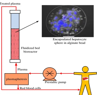
2.1 The fluidized bed bioartificial liver principle ... 31
2.2 Improved conditions under fluidization conditions ... 32
Chapter 3... 37
ix
3.1.1 Alginate preparation ... 38
3.1.2 Ringer solution... 39
3.1.3 Characterization techniques: size ... 40
3.1.4 Characterization technique: density ... 40
3.1.5 Characterization technique: swelling ... 41
3.1.6 Characterization technique: settling velocity ... 42
3.1.7 Mass transfer into the beads... 42
3.2 Expansion test and experimental rigs ... 44
3.2.1 Smaller (1-cm diameter) fluidization set-up ... 44
3.2.2 Bigger (10-cm diameter) fluidization set-up ... 45
3.2.3 Characterization of bed expansion ... 47
3.3 Effect of alginate beads on hepatocyte kinetic ... 48
Chapter 4... 49
Results and discussion ... 49
4. Results and discussion ... 49
4.1 Alginate bead size and density ... 50
4.2 Bead swelling properties ... 52
4.3 Terminal settling velocity ... 53
4.4 Mass transfer into the alginate beads ... 54
4.5 Expansion in the 1-cm and 10-cm columns ... 56
4.6 Effect of temperature ... 62
4.7 Albumin production (Effect of alginate bead encapsulation on kinetic of hepatocyte cell) ... 63
4.8 Conclusions ... 64
Part II ... 66
Hollow fiber membrane bioreactor ... 66
Chapter 5... 67
Hollow fiber (HF) membrane bioreactor ... 67
5. Hollow fiber membrane bioreactor ... 67
x
5.2 Typical set-up protocol and operational limitation ... 74
Chapter 6... 75 Experimental setup ... 75 6. Experimental setup ... 75 6.1 Bioreactor configuration ... 76 6.1.1 Geometry ... 76 6.1.2 Fabrication ... 78 6.2 Instrumentation ... 78
6.2.1 Capillary level tank ... 80
6.2.2 Level sensor (contactless capacitive CLC) ... 85
6.2.3 Liquid flow meter ... 88
6.2.4 Peristaltic pumps ... 89
6.2.5 Data acquisition board ... 91
6.2.6 DAQ Box ... 92
6.3 Software (MATLAB) ... 94
6.3.1 Create DAQ session ... 95
6.3.2 MATLAB interface ... 99
6.3.3 Signal sending to the pumps ... 99
6.4 Hydrodynamic and control experiment setup ... 100
Chapter 7... 102
Modeling and control system development ... 102
7. Modeling and control system development ... 102
7.1 Three-compartment dynamic modeling of bioreactor hydrodynamics ... 103
7.1.1 Mass balances ... 105
7.1.2 Geometrical description of the volume/height relationship ... 109
7.1.3 Linearization ... 112
7.1 Control system development ... 115
7.1.1 Scheme for controlled variables ... 115
7.1.2 Feedback multi-loop strategy with PID controllers ... 116
7.1.3 Input-output variable pairing and controller tuning ... 117
Chapter 8... 120
xi 8.2 Level dynamics – comparison of the linear and non-linear model results with
experiments ... 123
8.3 System response to step change in input variables – non-linear and linearized models ... 125
8.4 Control system and controller tuning ... 128
8.5 Level control ... 132
8.5.1 Level setpoint step-change ... 132
8.5.2 Inlet flowrate step-change... 136
8.6 Flowrate control (full hydrodynamics control) ... 138
8.6.1 Inlet flowrate step-change... 139
8.6.2 Automatic to manual switch (flowrate control disturbance) ... 142
8.6.3 Level setpoint step-change ... 145
8.7 Level control of bioreactor in actual cell culturing ... 146
8.8 Conclusion and outlook ... 150
References ... 152
Appendix A - MATLAB Scripts ... 161
Membrane bioreactor model ... 161
Control system ... 167
Appendix B – DAQ box manual ... 178
Appendix C – CLC level sensor manual ... 179
Appendix D – Flowmeter manual ... 182
Appendix E – Pump manual ... 186
Appendix F – DAQ manual ... 190
xii
List of Figures
Fig. 1. Different steps of liver failure [8]. ... 3 Fig. 2. Approaches to cellular therapies for the treatment of liver disease [9]. ... 4 Fig. 3. Classification of the different artificial and bioartificial organs for temporary liver
support [4]. ... 5 Fig. 4. Schematic representation of hollow fiber based bioartificial livers relying on commercial cartridges. The cells (hepatocytes) may be located either in the lumen [49, 59] or in the
extraluminal space [49, 50, 57]. Blood or plasma flows in the cell-free space. The membrane is employed as a barrier between the perfusion fluid and the hepatocytes. ... 13 Fig. 5. Schematic representation of the mat of fibers used in Berlin membrane-based bioartificial liver. □: open port; ■: closed port. (Adapted from [58]). ... 14 Fig. 6. Schematic description of Flendrig et al. [37] direct perfusion bioreactor (D). The
hepatocytes aggregates (C) are anchored in the 3D matrix located between the spirally wound polyester film (B). The hollow fibers (A) provide the cells with oxygen. ... 16 Fig. 7. Fixed bed and fluidized bed configurations of bioreactors exploiting hepatocytes
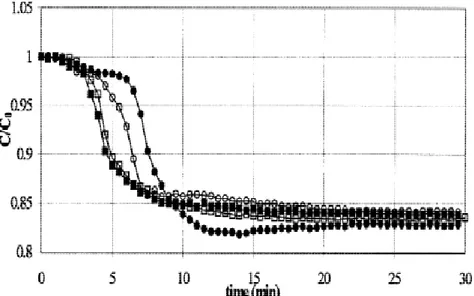
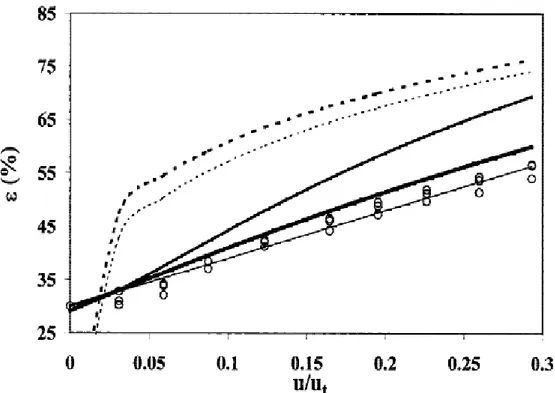
entrapment into spherical beads [4]. ... 18 Fig. 8. The principle of the fluidized bed bioartificial liver. ... 32 Fig. 9. The time courses of VitB12 concentration in the tank under dynamic mass transfer conditions are shown for 4 different perfusion flow rates: (●): Q = 29.4 ml/min, (○): Q = 40 ml/min, (■): Q = 55 ml/min, and (□): Q = 70.9 ml/min [75]. ... 33 Fig. 10. Shown is the time course of VitB12 concentration in the supernatant under static mass transfer conditions [75]. ... 34 Fig. 11. The graph shows the influence of the superficial velocity u (divided by the terminal velocity ut) on the fluidized bed porosity ε: (s) experimental data. The results are compared with
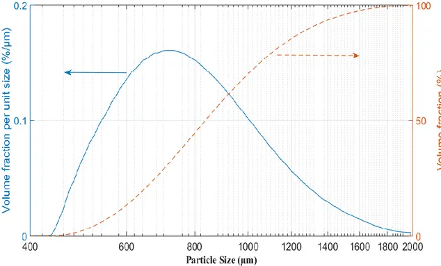
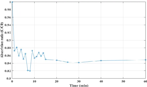
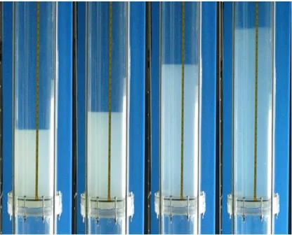
different models: - - - Foscolo et al. [89], … Richardson and Zaki [90], Hirata and Bulos [91], Ganguli [92], and Legallais et al. [79] ― Equation 1. ... 35 Fig. 12. Alginate preparation setup actual (top) and schematic (bottom) ... 39 Fig. 13. Settling velocity measurement ... 42 Fig. 14. Fluidized bed bioreactor used to study the transport of vitamin B12 into the beads (dynamic system) ... 44 Fig. 15. Experimental setup of the bioreactor with 1-cm diameter column. ... 45 Fig. 16. Experimental setup of the bioreactor with 10-cm diameter column. ... 46 Fig. 17. Particle size distribution for the alginate beads (Malvern Mastersizer 2000) using the volume fraction density (blue solid line) and cumulative volume fraction (red dashed line) plots. ... 50 Fig. 18. Comparison between the densities of inert alginate beads and beads with hepatocyte spheroids during one week. Standard deviation σ = 3 ... 52 Fig. 19. Sample microscope picture of inert alginate beads with the ruler scale (in mm units). . 53 Fig. 20. Size change (swelling) properties of alginate bead. Standard deviation in William’s E medium σ =0.04 mm and in Ringer solution σ =0.02 mm ... 53 Fig. 21. Alginate beads absorption trend in batch (static) condition ... 55 Fig. 22. Alginate beads absorption trend in fluidized (dynamic) condition ... 55
xiii
cm diameter columns. T = 20 °C. ... 58
Fig. 25. Voidage vs. velocity: comparison between 1 cm diameter and 10 cm diameter columns (test No. 1 in Table 6). Fitted parameters for the Richardson-Zaki equation (R-Z) are reported in Table 6. Ambient temperature (T = 20 °C). ... 58
Fig. 26. Comparison of alginate expansion in two different temperature (Two set of results are compared in case of 37 ° C) ... 63
Fig. 27. Albumin kinetic comparison between hepatocyte spheroid and encapsulated hepatocyte spheroid in alginate bead. ... 64
Fig. 28. Crossed hollow fiber membrane bioreactor ... 70
Fig. 29. The rate of albumin and urea synthesis of human hepatocytes cultured in the crossed HF membrane bioreactor. The values are expressed as µg/h 106 cells ± s.e.m. and are the mean of 6 experiments [6]. ... 71
Fig. 30. a) Diazepam concentration in the inlet medium (◊) and in outlet medium from bioreactor loaded with cells (○) in presence of 10 µM diazepam added to the culture medium. b) Formation of diazepam metabolites: (full bar) oxazepam, (gray bar) temazepam and (white bar) N-desmethyl-diazepam. The values are expressed as ng/h 106 cells ± s.e.m. and are the mean of 6 experiments [6]. ... 73
Fig 31. Schematic vertical section of the crossed hollow fiber membrane bioreactor [6]. ... 76
Fig 32. Bioreactor housing (left-a) and bioreactor assembled in-house, with 100 HFs (10x10 arrangement) in each bundle (right-b). ... 78
Fig 33. ITM-CNR membrane bioreactor set up before instrumentation. ... 79
Fig. 34. ITM-CNR membrane bioreactor set up with the multi input-multi output (MIMO) (2×2) control of hydrodynamics by two feedback loops on flowrate and liquid level. ... 80
Fig 35. Sketch of the capillary level tank (Side view). ... 82
Fig 36. Sketch of the capillary level tank (front and top view). ... 84
Fig 37. Capillary level tank. ... 85
Fig 38. CLC level sensor (a), CLC level sensor with a copper foil (b). ... 87
Fig. 39. A comparison of CLC level sensor accuracy measurement with and without copper foil ... 88
Fig 40. SENSIRION SLI 2000 flow meter. ... 89
Fig. 41. ISMATEC Peristaltic pump ... 90
Fig. 42. ISMATEC pump Analog interface details. ... 91
Fig 43. DAQ NI 6001. ... 92
Fig 44. DAQ box electrical circuit scheme. ... 93
Fig 45. Actual connections of the DAQ box. ... 94
Fig. 46. MATLAB software algorithm ... 95
Fig 47. Raw data vs. filtered data (Level). ... 97
Fig. 48. Raw data vs. filtered data (Flowrate). ... 98
Fig 49. MATLAB interface. ... 99
xiv Fig 51. Hollow-fibre membrane bioreactor scheme (a) showing the feed bundle (FB) zone through polyethersulphone, PES, membranes in red, the cell culture environment (extra capillary space, ECS) in yellow and the effluent bundle (EB) zone through the second, crossed set of membranes (also PES) in blue; the corresponding simplified three-compartment model of the bioreactor is also represented (b), also showing the model variable names for flowrates (F),
volumes (V) and concentrations of species like oxygen (CA) and urea (CB). ... 105
Fig 52. A Simulink block diagram of the three-compartment non-linear model. ... 108
Fig 53. Assumed geometrical shape of the cell culturing environment with a variable liquid level within the bioreactor and level sensor range on the side. ... 110
Fig. 54. Volume to height conversion in Simulink ... 112
Fig 55. A Simulink block diagram of the linear model. ... 114
Fig 56. Block diagram of PID control system. ... 117
Fig 57. A Simulink simulation block diagram of the controlled MBR. ... 118
Fig 58. Comparison between the measured height and the model predictions during bioreactor filling at constant flowrate... 122
Fig 59. Step change from 1.03 to 0.73 ml/min in the outlet flowrate. ... 124
Fig 60. The response in the level height of the linear, Linear, and experimental data to a step change in outlet flowrate. ... 124
Fig. 61. Response of 4 variables: a) Level, b) Oxygen concentration in the inlet, c) Oxygen concentration in the outlet and d) Oxygen concentration in the outlet for an input step change (increasing 50% of Oxygen concentration in inlet) ... 126
Fig. 62. Response of 4 variables: a) Level, b) Oxygen concentration in the inlet, c) Oxygen concentration in the outlet and d) Oxygen concentration in the outlet for an input step change (decreasing 50% of Oxygen concentration in inlet and increasing 50% of inlet flowrate) ... 127
Fig. 63. Response of 4 variables: a) Level, b) Oxygen concentration in the inlet, c) Oxygen concentration in the outlet and d) Oxygen concentration in the outlet for an input step change (increasing 50% of Oxygen concentration in inlet and inlet flowrate) ... 127
Fig 64. A comparison of the simulated MBR model response with and without controller (response of ECS level to 10% increase of outlet flowrate). ... 129
Fig 65. Comparison of the system with and without tuning. a) Liquid level, b) Outlet flowrate (manipulated variable)... 131
Fig 66. Measured flowrate variation (manipulated variable in the level control loop) as a result of step-changes in the level set-point in 10-by-10 mm steps from 80 to 50 mm. ... 133
Fig 67. Measured level evolution (controlled variable) as a result of step-changes in the level set-point in 10-by-10 mm steps from 80 to 50 mm. ... 134
Fig 68. Measured flowrate variation (manipulated variable in the level control loop) as a result of step-changes in the level set-point in 10-by-10 mm steps from 50 to 80 mm. ... 135
Fig 69. Measured level evolution (controlled variable) as a result of step-changes in the level set-point in 10-by-10 mm steps from 50 to 80 mm. ... 135
Fig 70. Measured outlet flowrate variation (manipulated variable in the level control loop) as a result of two (visible) step-changes in the inlet flowrate from 1.48 to 0.73 ml/min. ... 137
Fig 71. Measured level evolution (controlled variable) as a result of two (visible) step-changes in the inlet flowrate from 1.48 to 0.73 ml/min. ... 137
xv Fig. 73. Inlet flowrate set-point change (1.5 to 0.5 ml/min- by 0.25 ml/min step changes) - inlet flowrate (a), voltage sent to the pump 1 (flowrate controller) (b), bioreactor liquid level (c) and voltage sent to the pump 2 (level controller) (d). ... 141 Fig. 74. Inlet flowrate set-point change (0.5 to 1.5 and 1.5 to 0.5 ml/min) - inlet flowrate (a), voltage sent to the pump 1 (flowrate controller) (b), bioreactor liquid level (c) and voltage sent to the pump 2 (level controller) (d) ... 142 Fig. 75. Automatic control to manual as a flowrate control disturbance (0.5 to around 1.5 ml/min) - (a), voltage sent to the pump 1 (flowrate controller) (b), bioreactor liquid level (c) and voltage sent to the pump 2 (level controller) (d) ... 143 Fig. 76. Automatic control to manual as a flowrate control disturbance (1.5 to around 0.5 ml/min) - (a), voltage sent to the pump 1 (flowrate controller) (b), bioreactor liquid level (c) and voltage sent to the pump 2 (level controller) (d) ... 144 Fig. 77. Level set-point change from 50 to 80 mm (10 by 10 mm) - - (a), voltage sent to the pump 1 (flowrate controller) (b), bioreactor liquid level (c) and voltage sent to the pump 2 (level controller) (d). ... 145 Fig. 78. Level set-point change from 80 to 50 mm (10 by 10 mm) - inlet flowrate (a), voltage sent to pump 1 by flowrate controller (b), bioreactor medium level (c) and voltage sent to pump 2 by a level controller (d). ... 146 Fig 79. 24-hour bioreactor level control results during cell culturing at day 18 (a) and evaluation of oxygen consumption rate of cells cultured into the bioreactor at day 27 (b). ... 148
xvi
List of Tables
Table 1. Bioartificial liver support systems used in clinical trials [2]. ... 7
Table 2. Bioreactor designs and comparison [9] ... 20
Table 3. Comparison of albumin production by human hepatoma C3A cells entrapped in alginate beads in static incubation compared with fluidized bed bioartificial liver experiment . 36 Table 4. Density measurements of inert alginate bead ... 51
Table 5. Settling velocity of single alginate bead ... 54
Table 6. Inert beads hydrodynamic data and Richardson-Zaki parameters ... 59
Table 7. Dimensional properties of the bioreactor ... 77
Table 8. Instrument and DAQ variables in order to convert voltage to actual units ... 96
Table 9. Parameter definitions for the geometrical description of the height change with liquid volume ... 111
Table 10. Geometrical Model validation parameter values... 121
Table 11. Without tuning and tuned controller parameters ... 130
Table 12. Level control parameter values ... 132
xvii µ Viscosity Ar Archimede’s number CA Concentration component A D Column diameter d Particle size
Dmax Maximum of the instrument measurement limit
Dmin Minimum of the instrument measurement limit
g Local acceleration
G Transfer function
h Height h of a liquid column
h_0 Height of difference between sensor and bioreactor
h_c Height of cylinder
h_cap Height of the small cap at sphere/cylinder interface H_vlt Height of vertical layer total
k Correction factor
Kc Proportional gain
Km Michaelis-Menten constants.
L_fib Length of fiber
LM Level data
xviii
N_vlt Number of vertical layer total
Qf Flow rate
r Radius of the tube
R Raw data
r_c Radius of cylinder
r_fib Radius of fiber
r_s Radius of sphere
Re Reynolds’ number
u Superficial velocity
V_cap Volume of the small cap at sphere/cylinder interface V_fib Volume of one fiber
V_fibt Total volume of fiber
V_s Volume of sphere
V2 Liquid volume in the ECS
Vmax Michaelis-Menten constants
ʎ Relative gain parameter
ym Measured variable
ysp Set-point variable
γ Liquid-air surface tension
ε (t) Error value
ε Voidage
xix
τi Integral time
BAL Bioartificial liver devices
DAQ Data acquisition board
EB Effluent bundle
ECS Extra-capillary space
ELISA Enzyme-linked immunosorbent assay
ESLD End-stage liver disease
FB Feed bundle
FBBAL Fluidized bed bioartificial liver GND Ground
HEMA Hydroxyethyl methacrylate
HF Hollow fibers
HFMBR Hollow fiber membrane bioreactors
HFs Hollow fiber membranes
ID Internal diameter
IPA Isopropyl alcohol
MA Moving average
MBR Membrane bioreactor MIMO Multi input-multi output
xx
MWCO Molecular weight cut-off
NI National instrument
PEEK-WC Polyetheretherketone
PERV Porcine endogenous retrovirus
PES Polyethersulfone
PID Proportional–integral–derivative
PMMA Poly (methyl methacrylate) RGA Relative gain array
RTD Residence time distribution
SD Standard deviation
Teach-Chapter 1
General introduction and background of study
1. General introduction and background of study
In this chapter after a general introduction to liver failure and liver support, the technological aspects of the previously developed bioreactor devices like membrane-based devices, direct perfusion systems, and entrapment-membrane-based columns are reviewed. For each type, the technological requirements are theoretically addressed. At the end of the Chapter, the project motivations in relation to two important types of bioreactor such as fluidized bed bioreactor and hollow fiber membrane bioreactor are discussed.
General introduction
2
1.1 Liver failure
The liver performs many important metabolic functions and is the only internal organ that has the capacity to regenerate itself with new healthy tissues. Loss of liver cell functions may result in the disruption of many essential metabolic functions, which could lead to death. On the global scale, liver diseases are severe public health problems, with the incidences of end-stage liver disease (ESLD) rising annually. The impairment of liver functions has also serious implications and it is responsible for high rates of patient morbidity and mortality. Progresses made within the last decades in surgical techniques, intensive care, immunosuppressive regimen, and organ preservation methods have made liver transplantation a form of well-established and successful therapy [1]. The 5-year survival rate in the United States was 70.5% for deceased donor transplants performed in 2007. However, the existing shortage in avail- able donor organs allows no significant expansion of transplantation programs, and the number of patients on the waiting list for transplantation largely exceeds the number of donor organs available for transplantation [2, 3].
Presently, liver transplantation remains the treatment of choice for ESLD patients but it is limited by both the high costs and a severe shortage of donor organs. Fig. 1 shows different steps of liver failure [4-7].
3 Fig. 1. Different steps of liver failure [8].
Throughout the years, survival after transplantation has enhanced with advances in both patient administration and surgical methods, yet the strategy is not generally accessible in a convenient manner, stimulating new surgical methodologies, for example, split-liver transplantation, acquisition from living donors, and assistant liver transplantation. The issue of organ lack is exacerbated by the difficulty in anticipating the result of liver failure. The King's College prognostic criteria have been embraced by most focuses, in spite of the fact that they neglect to distinguish patients at generally safe of dying [9-11].
1.2 Liver support
Since 20 years, the growing crevice between the number of patients on holding up rundown and the number of liver transplants has highlighted the necessity for a temporary liver support [4].
Other options to entire organ transplantation for liver dysfunction are under dynamic examination. Fig. 2 schematically delineates the 4 fundamental cell approaches
General introduction
4 that are presently being explored: isolated cell transplantation, tissue engineering of implantable constructs, transgenic xenotransplantation, and extracorporeal bioartificial liver devices (BAL). Extracorporeal bolster for patients experiencing liver failure has endeavored for more than 40 years. Transitory frameworks have been produced to endeavor to assist recuperation from intense decompensation, encourage recovery, or serve as a scaffold to liver transplantation [12-21].
Fig. 2. Approaches to cellular therapies for the treatment of liver disease [9].
In the previous two decades, a few gadgets for liver support have been examined or created, which can be classified into two: purely artificial organs, in light of traditional strategies, for example, hemodialysis, plasmapheresis, specific or non-specific adsorption, and bioartificial organs (Fig. 3). As liver plays out numerous and complex functions (detoxification, transformation, synthesis), it has gotten to be apparent that mechanical or chemical forces cannot be adjusted to the treatment of intense liver diseases. In contrast, a bioartificial organ exploits a synthetic cartridge to host biological components such as liver cells (hepatocytes on account of a bioartificial liver). Such devices are presently being worked on and some have as of now achieved clinical trials Apart from the functionality and efficacy of liver support systems, safety issues have to be considered. In particular, systems used for supporting the liver function in diseased liver need to be stable over the treatment period and show reproducible functions to
5 ensure a standardized quality. In addition, investigation of the biocompatibility of materials used and preventing infection of patients are demanded to ensure the clinical safety of treatments [2, 4, 22].
Fig. 3. Classification of the different artificial and bioartificial organs for temporary liver support [4].
Different non-biological methodologies have met with restricted achievement, probably in light of the part of the synthetic and metabolic functions of the liver that are deficiently supplanted in these frameworks. Haemodialysis, hemoperfusion over charcoal or resins or immobilized enzymes, plasmapheresis, and plasma exchange have all been investigated. Alternately, absolutely biological methodologies have demonstrated empowering brings about a few cases, however, have been difficult to execute in the clinical setting. Notwithstanding orthotropic liver transplantation, these incorporate entire organ perfusion, perfusion of liver slices, and cross hemodialysis [21].
1.3 Bioartificial liver
Bioartificial devices typically incorporate isolated cells into bioreactors to simultaneously promote cell survival and function as well as provide a level of transport seen in vivo [23]. In order to adequately compensate the metabolic and regulatory
General introduction
6 performances of the failing organ in clinical application, bioartificial liver support systems have to:
Provide differentiated, human-specific hepatic functions
Procure sufficient cell quantities for efficient liver support in patients Ensure the stable maintenance of metabolic activities
Enable a reproducible cell quality for standardized clinical applications
Ensure the clinical safety of the system, in particular, with respect to the cell source used
Allow the flow of blood and plasma with a mass exchange that can quantitatively address the required metabolism for the patient and the possible metabolism of the cells
Ensure that problems of blood cell damage and coagulation during blood per- fusion can be avoided
Avoid negative interactions with the patients’ coagulation system, while anticoagulation may be required [2].
An important challenge in engineering devices for culturing liver cells is the development of bioartificial systems that are able to favor the liver reconstruction and to modulate liver cell behaviour. Bioreactors allow the culture of cells under tissue specific mechanical forces (e.g. pressure, shear stress and interstitial flow), augmenting the gas and nutrient exchange under fluid dynamics control that ensures the long-term maintenance of cell viability and functions [6]. Table 1 gives an overview of bioartificial liver support systems that have been clinically used for extracorporeal liver support. Most of these systems represent two-compartment devices where the cells reside in the space between perfused hollow-fiber capillaries serving for plasma or blood perfusion [2].
7 Table 1. Bioartificial liver support systems used in clinical trials [2].
Bioreactor Technology Cell type used Clinical outcome
Hollow fiber–based bioartificial liver device perfused with plasma (ELAD)[24, 25]
Human hepatoblastoma cell line(C3A)
No significant difference in survival, improvement in galactose elimination and encephalopathy
Hollow fiber–based bioartificial liver device perfused with whole blood(BLSS)[26, 27]
Primary porcine hepatocytes No serious adverse events; treatment well tolerated by patients
Hollow fiber–based bioartificial liver with hepatocytes attached to dextranmicro carriers (HepatAssist)[28]
Cryopreserved porcine hepatocytes
Tendency toward improved survival, yet not significant
Amsterdam Medical Centre Bioartificial Liver Device (AMC-BAL)[29]
Primary porcine hepatocytes No severe adverse events, successful bridging to liver transplantation shown Radial flow bioreactor perfused
with plasma (RFB-BAL)[30]
Primary porcine hepatocytes Improvement of encephalopathy level, decrease in ammonia and transaminases
Hollow fiber–based bioartificial liver with integral oxygenation (MELS)[31, 32]
Primary porcine or human liver cells
No severe adverse events; in some patients, clinical and/or biochemical improvement
1.3.1 Cellular component of bioartificial liver devices
The full supplement of cellular functions required in BAL devices to impact positive clinical results has not been resolved. To address this issue, surrogate markers of every class of liver-specific functions commonly are described including synthetic, metabolic, detoxification (stage I and II pathways), and biliary discharge [33, 34]. The certain suspicion is that hepatocytes fit for a wide cluster of known functions will likewise express those unmeasured (or obscure) functions that are integral to their metabolic part. Each of these primary hepatocytes, cell lines, and stem cells ought to be assessed on the
General introduction
8 premise of accessibility, potential unfriendly connections, and efficacy in giving liver-specific function [9].
Primary porcine hepatocytes are most commonly used in devices undergoing preclinical and clinical evaluation. Primary hepatocytes, in particular, have a unique microenvironment in vivo and they notoriously lose their liver-specific functionality and/or viability in vitro. Additionally, the proliferation of mature human hepatocytes in vitro if present is very limited. Isolated hepatocytes represent a good model of liver metabolism because they are able to perform the full range of known in vivo biotransformation, synthetic and detoxification functions [35-38].
Although primary hepatocytes represent the most direct approach to replacing liver function in hepatic failure, they are anchorage-dependent cells and notoriously difficult to maintain in vitro. There is relatively limited information on the maintenance of liver-specific functions of hepatocytes. They rapidly lose their liver specific functions when maintained under the standard in vitro culture conditions. When enzymatically isolated from the liver and cultured in monolayer or suspension cultures, they rapidly lose adult liver morphology and differentiated functions. Many investigators have looked at the microstructure of the liver to provide inspiration for culture models that replace the lost cues from the hepatocyte microenvironment in vivo [9, 37, 38].
1.3.2 Bioreactors as bioartificial devices
This short-sighted approach comprises in considering such a device as a bioreactor in view of synthetic components ready to offer a satisfactory situation to the liver cells. This environment would thusly prompt to the support of efficient functions of the cells going for liver supply when putting in a bioreactor situated in an extracorporeal circuit [4].
The obligatory prerequisites for worthy cell viability and functions in a bioartificial liver (BAL) are likely recorded beneath, as indicated by a biotechnological perspective:
1. Anchorage to a support or a matrix.
2. Compelling exchanges with blood or plasma in order to - Receive satisfactory oxygen and supplements supply,
9 - Be in contact with the toxic substances and catabolites typically expelled from the blood by the liver (e.g. bilirubin),
- Release synthesized metabolites (e.g. urea, albumin, coagulation factors) to the blood stream.
3. Assurance from host immunological reaction.
Likewise, the synthetic segments of the bioreactors should themselves be biocompatible. A few bioreactor designs have been proposed to fulfill the vast majority of the above conditions [4].
1.4 A background of study on different type of bioreactors
1.4.1 Membrane-based bioreactors
Once the requirement for the incorporation of cellular compounds into an extracorporeal bioreactor got to be obvious, a few research groups exploited the membrane modules effectively produced for pure artificial organs. The flat sheet or hollow fiber hemodialysers, and additionally plasmafilters had effectively demonstrated their ability for solute and oxygen transport and their relative biocompatibility towards the patient's blood or plasma. Membranes were what's more ready to give an immune barrier between the hepatocytes and the perfusion fluid, and could likewise be utilized for cell anchorage [4].
In the accompanying, we first introduced how membranes and membrane reactors may hypothetically address the prerequisites beforehand drawn for an efficient BAL. From this investigation, we along these lines introduced and talked about the BAL under development [4].
1.4.1.1 Cell anchorage
There is an extensive variety of membrane materials utilized in extracorporeal circuits. They all demonstrated their relative biocompatibility with either blood or plasma,
General introduction
10 yet before their application to bioartificial organs and particularly BAL, they had never been investigated in term of cell adhesion and development. Hence, a few parameters, for example, the type of polymer, the hydrophobicity or wettability, and the surface roughness were explored [39-45].
A few conclusions may be drawn from the gathered information: would cell attachment on membrane surface be looked for, the material ought to be hydrophilic and electrically charged (either emphatically or adversely) [40-42, 44].
The charge density appeared to essentially influence the cell adhesion, and thus the cellular integrity. From this point of view, polysulfone membranes appeared as the best material and gave the best yield as far as metabolic exercises. Cellulose-based membranes were substantially less appealing. The membrane roughness did not influence cell adhesion, and thus cell activities, for example, oxygen consumption or ammonium elimination kinetics [45]. In fact, the best cell adhesion, integrity, and prolonged viability were acquired after the membrane polymer coating with collagen or fibronectin [43]. These perceptions were in concurrence with information from Biagini et al. [46] demonstrating an improved fibroblasts adhesion and expansion on utilized dialysis membranes, i.e. materials on which a protein layer was stored.
This sort of coating offered a more appropriate environment for hepatocytes and was generally utilized with even non-porous materials. In any case, the direct attachment of hepatocytes to one membrane side could avoid efficient trade between both membrane sides. Along these lines, cell attachment could ideally be accomplished on different sorts of the matrix, for example, Collagen [47-49], Agarose [50] or Matrigel [51], set either in the lumen or the extraluminal part of the membrane. In these cases, the membrane would just be utilized as an exchanger and immunological barrier.
1.4.1.2 Sieving properties
Two types of membranes have been utilized as a part of present extracorporeal circuits. The first is an ultrafiltration membrane with a maximum molecular weight cut-off (MWCO) of around 70 kDa (molecular weight of albumin). The basis for utilizing
11 this kind of membrane as a part of BAL was the related immune barrier: such a membrane prevented xenogenic hepatocytes from immune rejection and conversely the patient from the dangers of hypersensitivity reactions and xenozoonosis. Subsequently, the evacuation of albumin-bound toxins or the discharge into the perfusion fluid of the novo-synthesized proteins was frustrated or even counteracted [52, 53].
The second is a microporous membrane with a mean pore size of around 0.2 mm which permits the exchange of even high molecular weight proteins which could prompt to the immunological hazard said above. However, a later in vitro study from Mullon [54] showed that a 0.15 mm pore size polysulfone membrane decreased the danger of porcine endogenous retrovirus (PERV) transmission by an element of 100,000.
1.4.1.3 Bioreactor geometry
Because of compactness and efficiency imperatives, hollow fiber membranes appeared to be a great deal more sufficient than flat sheet membranes. The solute mass transfer from the blood or plasma compartment to the cell compartment and the other way around in a membrane-based bioreactor did rely on upon the membrane type, as well as on the bioreactor geometry and the area of both compartments. As portrayed in detail by Catapano [55], mass transport experienced constraints in three unique areas: perfusion fluid (blood or plasma), membrane structure and cell compartment. Contingent on the bioreactor design, the solute mass transfer inside these three zones could be significantly distinctive. Inside these compartments, phenomena in charge of mass transport could be diffusion, convection, or both.
In the perfusion fluid side, mass transport was unequivocally influenced by the fluid velocity and viscosity. By relationship with hemodialysis, the flow of the perfusion fluid on the shell side (hepatocytes on the lumen side) could bring about zones where fluid was practically stagnant, and thus exceptionally poor diffusive transfer may happen. As highlighted by Catapano [55], the higher the velocity the better the mass transport. In term of viscosity, the utilization of plasma rather than blood, other than encouraging biocompatibility to the detriment of system complexity, resulted in a significant viscosity decrease for the perfusion fluid which on a basic level favored mass transport. In any case, Zydney et al. [56] depicted the impact of the presence of rotating red blood cells on solute effective diffusion in blood. These hypothetical contemplations contended for the
General introduction
12 nearness of the hepatocytes on the shell side, yet don't take into consideration conclusion on the choice of fluid [4].
Membrane permeability for a solute decreases with the increase of its molecular size. It additionally relies on upon the solute shape and size. Other than the immunological measure, the membrane MWCO may speak to the key purpose of exchanges between perfusion fluid and hepatocyte [4].
In the cell compartment, mass transport unequivocally relied on compactness and density. The distinctive procedures utilized to give the cells with an adequate anchorage might here assume a critical part. In spite of a 3-D arrangement, the hepatocytes situated in the fiber lumen experienced a low contact region and additionally starvation for those situated a long way from the membrane. On the shell side, the cell viability emphatically depended on its accessibility. The collagen matrix offered an efficient anchorage but was in charge of low diffusion coefficients. The attachment to microcarrier could allow the presentation of every cell to the medium, additionally relied on upon the level of filling for the bioreactor [4].
Taking everything into account, hypothetical contemplations may be useful to maintain a strategic distance from a few mix-ups in the origination of a membrane-based BAL. In any case, they didn't prompt to the definition of the ideal design, since many inquiries were not completely replied [4].
1.4.1.4 Choice of membrane material
In the vast majority of frameworks, a polysulfone-based membrane was favored in concurrence with its better connections with the hepatocytes, despite the fact that cells were not attached directly to it [49, 50, 57]. Gerlach [58] has built up a bioreactor with three separate capillary membrane systems, according to the functions dedicated to each membrane (nutrient/plasma input or output, gas exchange).
1.4.1.5 Bioreactor design
Bioreactor designs differed from classical (hemodialysers) to more entangled geometry. In traditional membrane modules, the fluid flowed either inside or outside the fiber lumen, the hepatocytes being situated on the opposite side (Fig. 4). Filling the
13 bioreactor with hepatocytes on the membrane shell side appeared to be favored for practical reasons. Gerlach et al. [51] proposed a more intricate geometry including a mat of three diverse fibers offering a 3D environment to the cells seeded at the external surface and among the capillaries.
Fig. 4. Schematic representation of hollow fiber based bioartificial livers relying on commercial cartridges. The cells (hepatocytes) may be located either in the lumen [49,
59] or in the extraluminal space [49, 50, 57]. Blood or plasma flows in the cell-free space. The membrane is employed as a barrier between the perfusion fluid and the
hepatocytes.
As shown in Fig. 5, each fiber type was perfused with various fluids (oxygen, nutrients during the culture period, plasma under powerful BAL function). Plasma or culture medium entered the bioreactor by means of a fiber bundle under dead end filtration conditions, and left by means of another bundle, resulting in adequate exchanges with the hepatocytes [58].
General introduction
14 Fig. 5. Schematic representation of the mat of fibers used in Berlin membrane-based
bioartificial liver.
□
: open port;■
: closed port. (Adapted from [58]).Since no randomized tests have been defined yet, it appeared difficult to separate the distinctive bioreactors' efficiency. In any case, bioreactors using upgraded convective mass transfer seemed more efficient than those depending on pure diffusion. In the Circe bioreactor, the high perfusion flow rate (400 ml/min achieved by plasma recirculation) associated with a long plasmapheresis membrane (500 mm length) yielded high inside filtration flow rate took after by back filtration which enhanced transfers in both the directions [60]. Albeit other authors [40] recommended that pure diffusion techniques could be beneficial on account of the low concentration gradient produced on both sides of the membrane, no clinical information managed this approach.
1.4.1.6 Summary
The experience of the distinctive groups required in the origination of a membrane-based BAL demonstrated that some preparatory limitations could be kept away from with no malicious impact on the BAL functions. The efficient mass transfer of toxins and metabolites, furthermore most likely of oxygen, as opposed to the regard of
15 a tight immunological barrier, showed up as a key point for a reliable short-term BAL use.
It is in certainty extremely difficult to dissect the genuine efficiency of every framework and still many inquiries are opened. Particularly, the optimal amount of hepatocytes to be utilized has not been defined yet. Would it be bigger than that typically utilized for the occasion, the membrane bioreactors, even exceptionally appealing, could suffer from scaling-up difficulties [55]: expanding the number of hepatocytes into a similar cartridge could bring about a significant loss of mass transport and hence viability. Likewise, the impact of membrane fouling under high filtration flow rate has not been explored as such and could be a restricting component in future utilizations of such BAL [61].
1.4.2 Direct perfusion bioreactors
The direct perfusion of connected cells by plasma or blood into a bioreactor appears an encouraging and basic idea, which was taken up by a few research groups.
Two principle methodologies were under scrutiny. The first one endeavored at making a 3D environment for the liver cells, looking like the native organ [61-63]. The cells could form small aggregates, or be specifically appended to a porous support. They were in this way independently perfused, under a low dispersion slope as in a typical liver [61]. The other approach depended on more conventional cell culture as monolayers between two collagen-coated plates [64-66]. The restricting sinusoidal surfaces of the hepatocytes were joined to the extracellular matrix, duplicating the in situ configuration of the intact liver. Non-parenchymal cells could be deliberately added to enhance the hepatocyte functions [64].
General introduction
16 Fig. 6. Schematic description of Flendrig et al. [37] direct perfusion bioreactor (D). The
hepatocytes aggregates (C) are anchored in the 3D matrix located between the spirally wound polyester film (B). The hollow fibers (A) provide the cells with oxygen.
A portion of the above bioreactors additionally utilized a few sections of membrane technology. Flendrig et al. [62] utilized hydrophobic polypropylene hollow fiber membranes for oxygen supply and Carbon Monoxide evacuation. The homogenous dispersion of the fibers went about as a spacer for the spirally twisted polyester film, reinforcing the 3D environment offered to the hepatocytes (Fig. 6). The idea of this type of bioreactor ought to encourage the scaling-up. Bader et al. [65] developed the hepatocytes on collagen-coated microporous membranebut, as Flendrig, did not use this membrane as a barrier between the cells and the perfusion fluid.
For the occasion, none of the displayed frameworks have achieved the clinical trials. Despite the fact that the mass exchanges ought to be streamlined, the scaling up of a few frameworks (particularly the plates) appeared difficult to perform. Likewise, hepatocytes could be subjected to high shear in some configurations, prompting to cell harm or conceivable discharge to the circulation system. With respect to most layer based frameworks, just constant culture permitted the capacity of such BAL [4].
17
1.4.3 Entrapment-based bioreactors
Another option to the above configurations was the incorporation of hepatocytes inside a semi-permeable spherical structure more often than not called “bead” or
“capsule” [67]. The polymer bead matrix offered anchorage facilities to hepatocytes and its porous structure could go about as an immunological barrier.
The hepatocytes containing beads were first created by Tompkins et al. [68] and Dixit [19] for their direct implantation. Hepatocytes viability was observed to be kept up in such a tridimensional structure [69], even after cryopreservation [70]. The beads may even shield the cells from shear stress damage in an extracorporeal bioreactor. Since cell encapsulation is a broadly utilized instrument as a part of biotechnology, a few materials have been examined to fulfill the prerequisites of a bioartificial liver. A few groups tried the properties of Hydroxyethyl methacrylate-methyl methacrylate (HEMA-MMA) copolymer [71], chitosan-dextrose [72]. Calcium alginate was up to now the most famous material [8, 73] in view of its porosity, its mechanical properties, and its biocompatibility. The alginate bead external structure may be reinforced by the expansion of chelating segments (lysine for instance). The bead diameter ranged from 1 mm or less, taking into account sufficient mass transfer and oxygenation of all the hepatocytes. This size was appeared to be greatest by Sardonini et al. [74] whose findings demonstrated an ideal cell to a medium distance of 370 mm to keep up high cell viability. What's more, hepatocytes into alginate bead may be easily stored by cryopreservation [70].
A large portion of the bioreactors intended for beads perfusion relied on fixed bed configuration (Fig. 7), where the beads were densely packed into a column. Reactors intended for small animal trials worked appropriately [73]. Their significant restriction for scaling-up was the perfusion velocity profile into the column: the arrangement of preferential channels resulted in poor perfusion for a lot of beads and subsequently constrained mass transport outside the beads.
Furthermore, high shear stresses on the successfully perfused beads could prompt to conceivable harm on the beads structure, and as an impact to alginate and cells discharge to the blood stream. Nonetheless, the hepatocytes entrapment into alginate beads still seemed promising since the various criteria fixed for an operational BAL appeared to be fulfilled. Thus, it was proposed to make use of the possibility of hepatocytes entrapped in alginate beads in a more efficient bioreactor. In this novel
General introduction
18 geometry, beads were subjected to a fluidized bed movement, prompting to the definition of a fluidized bed bioartificial liver (FBBAL) [75].
Fig. 7. Fixed bed and fluidized bed configurations of bioreactors exploiting hepatocytes entrapment into spherical beads [4].
The utilization of fluidized bed reactors was generally spread in chemical or biochemical engineering when a diphasic blend was available [76]. In the mix with cells entrapped into beads, it has likewise found a few biotechnological applications [77]. Thus we recommended to apply this innovation to a vast scale extracorporeal BAL, committed to in vivo applications on pigs [78] and as an extension of the past work of Fremond et al. [73] with a small-scale bioreactor. The in vivo application required the utilization of 300–400 ml of alginate beads (diameter 1 mm) containing porcine hepatocytes. The perfusion plasma flow rate ought to run 20–30 ml/min and the dead volume minimized. The framework created was depicted in detail somewhere else [75] and first approved with saline solution at 20 °C rather than plasma at 37 °C (same viscosity) and empty beads
19 (supposed to be lighter than the cells containing ones) [79]. The fluidization was gotten from the fixed bed status by increasing the superficial velocity (Fig. 7).
The bed expansion suggested utilizing a column with a smaller diameter (to work at the same flow rate) and a larger height than a fixed bed column. Under optimized hydrodynamic conditions, bed expansion was steady and brought about a homogenous mixing [4].
The outcomes obtained with this kind of bioreactor and empty beads are extremely reassuring. In vivo animal trials were performed in Rennes, demonstrating an alternate conduct with hepatocytes containing beads. The following stride in the bioreactor advancement comprises of in vitro experimental trials with plasma and entrapped hepatocytes [4].
General introduction
20 Table 2. Bioreactor designs and comparison [9]
Hollow fiber Flat plate and monolayer Perfused beds/Scaffolds Encapsulation and suspension Pros: attachment surface, potential for
immunization, well
characterized, cells protected from shear
Pros: uniform cell distribution and microenvironment
Pros: ease of scale-up, promotes 3-dimensional architecture, minimal transport barrier
Pros: ease of scale-up, uniform
microenvironment
Cons: non-uniform cell distribution, transport barrier with
membranes or gels
Cons: complex scale-up, potential large dead volume, cells exposed to shear, low surface area-to-volume ratio
Cons: non-uniform perfusion, clogging, cells exposed to shear forces
Cons: poor cell stability in suspension, transport barrier due to
encapsulation, degradation of microcapsules over time, cells exposed to shear forces
1.5 Motivation and objectives
The fluidized bed and hollow fiber bioreactors are the most promising technologies. In their operation, several issues arise because of the complex hydrodynamics and mass transport; so, there is a need to characterize the dynamics (in the sense of dynamical operation of the fluidized bed vs. packed/static configurations) and possibly apply instrumentation for automatic control. The details about problems and issues related to these two type of bioreactors and the most important objectives of present work are discussed in the two further sections.
21
1.5.1 Fluidized bed bioreactor
Hepatic cells in the form of spheroids immobilized within alginate beads in fluidized bed devices have been recently subjected to tests and successfully validated in preclinical trials with respect to biological functions and metabolic activity [80]. The effect of alginate preparation and beads size on the mass transfer and metabolic activity has been investigated by Gautier et al. [81] and other groups [82]. Generally, it has been shown that the overall performance of the fluidized bed bioartificial liver strongly relies on the effective hydrodynamics and mass transfer in the bioreactor. Unfortunately, in real applications, the expansion of the beads is not clearly visible even in transparent bioreactors, as the fluidization medium may be opaque. As it is well known, measures of the pressure drop are also of little use to characterize expansion once the minimum fluidization velocity is overcome. Mass transport between the fluid and the cell encapsulating alginate beads is also connected to the expansion in a complicated way, as an increase in velocity tends to overcome transport limitations on the exterior of the cells but also increase the voidage, i.e. decreasing the contact surface area per unit volume. Therefore, the ability to accurately predict the expansion properties of the beads’ bed is very important to the efficient use of the bioreactor.
The investigation related to fluidized bed bioreactor was carried out in a cooperation with the University of Compiegne. The main objective of the first part of this work is to provide data and analysis useful to the selection of the optimal hydrodynamic regime in the design and scale-up of bioartificial devices based on the fluidized bed of alginate beads. This is achieved first by preparing relatively monodisperse alginate beads, followed by a careful evaluation of their properties with specific respect to the characteristics influencing fluidization, including density (pure alginate and/or presence of hepatocytes), average size and size distribution, swelling characteristics in different culture media. It shall be emphasized that such properties of alginate are rather peculiar in comparison with more traditional particulate materials in fluidized beds (e.g. sand, fuel particles, and catalysts). For example, the density of alginate is very similar to that of water, also affected by possible swelling, making its correct determination crucial.
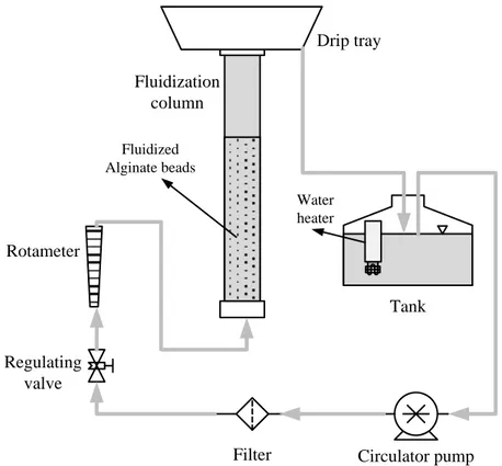
Fluidization properties are then investigated using Ringer solution as fluidization medium. A comparative hydrodynamic analysis is carried out of the expansion rate of the prepared beads up to very high voidage values in a 1-cm vs. 10-cm internal diameter
![Fig. 2. Approaches to cellular therapies for the treatment of liver disease [9] .](https://thumb-eu.123doks.com/thumbv2/123dokorg/2868948.9231/24.892.284.611.350.685/fig-approaches-cellular-therapies-treatment-liver-disease.webp)
![Fig. 3. Classification of the different artificial and bioartificial organs for temporary liver support [4]](https://thumb-eu.123doks.com/thumbv2/123dokorg/2868948.9231/25.892.186.709.251.572/classification-different-artificial-bioartificial-organs-temporary-liver-support.webp)
![Fig. 7. Fixed bed and fluidized bed configurations of bioreactors exploiting hepatocytes entrapment into spherical beads [4]](https://thumb-eu.123doks.com/thumbv2/123dokorg/2868948.9231/38.892.171.718.226.707/fixed-fluidized-configurations-bioreactors-exploiting-hepatocytes-entrapment-spherical.webp)