ALMA MATER STUDIORUM - UNIVERSITÀ DI BOLOGNA
FACOLTA’ DI INGEGNERIA
CORSO DI LAUREA SPECIALISTICA IN INGEGNERIA CIVILE
DICAM
TESI DI LAUREA
in
PROGETTI DI STRUTTURE L-S
EXPERIMENTAL STUDY ON CARBON FRP-CONFINED ELLIPTICAL CONCRETE COLUMNS
CANDIDATO: RELATORE:
Casalboni Stefano Chiar.mo Prof. Savoia Marco
CORRELATORE/CORRELATORI: Chiar.mo Prof. Teng Jin-Guang
Dr. Lam Lik
Anno Accademico 2010/11 Sessione II
3
ABSTRACT
It is well recognized that the technique of strengthening reinforced concrete (RC) using fiber-reinforced polymer (FRP) jackets is more effective for circular sections, but less effective for rectangular sections. Indeed the presence of angular corners does not permit a uniform confinement to be provided by the FRP jackets to the columns. While rounded corners can enhance the effectiveness of FRP confinement, it will be more efficient to modify the rectangular section into an elliptical section.
In addition to the better confinement effectiveness, from an aesthetical point of view, the shape modification would be a surprise to the built environment.
This paper presents an experimental study on the behavior of FRP-confined concrete columns with elliptical section.
Thirty-two short columns, divided in eight batches, were tested under axial compression.
Each batch presents four specimens with different elliptical sections, determined by the aspect ratio a/b, that is the ratio between the minor and mayor axis. By varying this value from 1.0 to 2.0 (1.0, 1.3., 1.7, 2.0), the section becomes more and more elliptical starting from a circular shape. In this way it is possible to study the trend of effectiveness of FRP confinement for different section geometries.
It is also interesting to study how the confinement effectiveness may vary by changing the cylinder strength of concrete and the number of the layers of CFRP. For this reason, a cylinder strength of concrete of 25 and 45 MPa have been used for the present research work, and half of the specimens were wrapped by one layer of CFRP, while the remaining specimens were wrapped with two layers.
A simple analysis of the results has been carried out for evaluating the experimental work described in the present document.
Further studies and analysis on this work should help to achieve a new and more accurate stress-strain model for CFRP-confined concrete columns with an elliptical section.
4
ACKNOWLEDGEMENTS
The author would like to express his gratitude to his supervisor, Professor Marco Savoia for his generous availability and support. Professor Savoia, thanks to his important role in the international academic world , was able to give the author the chance to have a wonderful experience in the Hong Kong Polytechnic University under the supervision of Professor Jin-Guang Teng. Professor Teng has achieved remarkable success in his scientific career. His rigorous approach to academic research, the breadth and depth of his knowledge of structural engineering, and his creativity and insight into many scientific problems, have made him one of the most important academics in the world in structural engineering, particularly relating to FRP composites. The author would also like to thanks his co-supervisor, Dr Lik Lam, for his generosity in support and valuable advice.The author is grateful to the Hong Kong Polytechnic University for its financial support in conducting the experiments and to the Structural Laboratory of the Department of Civil and Structural Engineering for its technical support. The author is very grateful to the Laboratory’s technical staff, in particular Mr. K.H. Wong, Mr. K. Tam, Mr. W.C. Wong and Mr. T.T. Wai for their valuable advice and assistance during the experimental program.
Special thanks go to Mr. X.L. Fang, without whom the present experimental work could not have been completed. The author cannot forget the friendly support and suggestions given by Mr. B. Zhang, Mrs. F. Zhang, and he would like particularly to thank Mr. B. Fu, for his generosity and affectionate friendship. Other important thanks must go to Mr. G. Lin, whose help in many smaller and yet laborious particulars was indispensable.
Last, but certainly not the least, the author is greatly indebted to his parents, Franco and Paola, to his brother, Federico, to his sister, Lucia, and to all his relatives for their constant and indefatigable love and support, understanding and encouragement.
5
Of course, the author expresses thanks to all of his friends, truly the pillars of his life.
6
CONTENTS
ABSTRACT ... 3 ACKNOWLEDGEMENTS ... 4 CONTENTS ... 6 CHAPTER 1 ... INTRODUCTION ... 9 1.1 Background ... 91.2 Objectives and scope ... 11
1.3 Contents ... 11
1.4 References ... 13
CHAPTER 2 ... 15
LITERATURE REVIEW ... 15
2.1 Introduction ... 15
2.2 Existing experimental studies on FRP-confined elliptical concrete columns ... 15
2.2.1 Test database ... 17
2.3 Theoretical models for FRP-confined elliptical concrete columns ... 19
2.2.2 Equation for compressive strength by Lam and Teng (2002) ... 19
2.2.3 Stress-strain model proposed by Pantelides et al. (2004)... 22
2.4 References ... 26
CHAPTER 3 ... EXPERIMENTAL PROGRAM ... 27
3.1 Introduction ... 27
3.2 Experimental test program ... 28
7
3.2.2 Specimens preparation ... 31
3.2.3 Instrumentation and Test ... 48
3.3 Material properties ... 50
3.3.1 Concrete ... 50
3.3.2 Carbon FRP (CFRP) ... 52
3.4 References ... 53
CHAPTER 4 ... EXPERIMENTAL RESULTS AND COMPARISON WITH EXISITING MODELS ... 54
4.1 Introduction ... 54
4.1.2 Test results database... 54
4.2 Compressive Strength ... 57
4.3 Ultimate Axial Strain ... 60
4.4 Stress-strain behavior ... 62
4.4.1 Shape of stress-strain curve ... 62
4.4.2 Minimum amount of CFRP for bilinear stress-strain curve ... 70
4.5 Hoop strain and failure modes ... 72
4.5.1 Hoop strain’s analysis ... 72
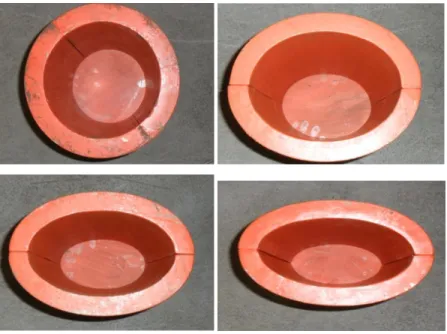
4.5.2 Failure modes ... 84
4.6 References ... 95
CHAPTER 5 ... CONCLUSIONS AND RECOMMENDATIONS FOR FUTURE RESEARCH ... 96
5.1 Conclusions ... 96
5.2 Recommendations for future research ... 97
9
CHAPTER 1
INTRODUCTION
1.1 Background
In the last forty years Fiber Reinforced Polymer (FRP) composites have been vastly employed in structural engineering and have undergone a crucial developments. FRP composites, due to its properties such as light weight, good corrosion resistance, large strength to weight ratio and high efficiency of construction, can be often considered more advantageous than the steel. The most important application of the FRP composites is their employment in providing confinement for the concrete in retrofitting existing columns with an FRP jacket (Priestley and Seible 1997,Lam and Teng 2002, Pantelides et al. 2004, Pan, Xu and Hu 2005, Ilki et al. 2006). For instance bridge columns may usually suffer of insufficient capacity or displacement ductility, buckling, deterioration of the concrete, earthquake attacks, etc.
As we already know thanks to the studies conducted by several authors, including Mirmiran and Shahaway (1997), Mander, Priestley and Park 1998, Spolestra and Monti (1999), Xiao and Wu (2000), Lam and Teng (2003), Pantelides et al. (2004), who have introduced several kinds of stress-strain models for FRP-confined concrete, the jacket, which performs an effective lateral confinement to the concrete columns, is the main reason for the increase of compressive strength and ultimate axial strain of the columns. Thus, the main matter for civil engineers is a good understanding of the stress-strain model, in terms of curve shape, ultimate condition, compressive strength and strain equation; a good result in such research would lead to a more reliable and cost-effective design.
At the same time, other important research works, carried out by Rochette and Labossier (2000), Pessiki et al. (2001), Ilki et al. (2002), Lam and Teng (2003), Campione et al. (2007), Parvin and Schroeder (2008), clearly point out that
FRP-10
confined concrete members subjected to membrane loading may ensure more effectiveness than those having long flat sides and corners, as they are affected by the predominant bending action. Since the effectiveness of confinement generally increases with the corner radius, it becomes necessary to round the corners, otherwise it would not be possible to achieve significant strengthening for the concrete. Moreover it could also happen that the presence of internal steel reinforcement decreases the radius to a small value, inducing an additional cause for further reduction in the effectiveness of the confinement.
In order to avoid such problems, one possible solution is to modify the shape of the section (Lam and Teng 2002, Pantelides et al. 2004, Pan, Xu and Hu 2005, Pantelides et al. 2007, Campione et al. 2007, Parvin and Schroeder 2008, Pantelides et al. 2010). This means changing a rectangular or square section into an elliptical or oval one, respectively. Two main different methods can be used to obtain the shape modification (Pantelides et al. 2004): one is performed with a subsequent FRP wrapping around the section; but this type of shape modification is hard to realize in practice. On the other hand, a prefabricated elliptical/oval/circular FRP shell may be used as the formwork for casting additional grout around the section. In addition, by using expansive cement concrete as the grout, a post-tensioning effect to the FRP jackets is achieved.
Others authors, like Parvin and Schroeder (2008), affirm that shape modification may be more practical for rectangular bridge columns, where space is not limited to accommodate additional column cross-sectional area. This method is also practical for building structures where space permits. Furthermore we should take in account that elliptical concrete columns are widely used for aesthetically pleasing structures and in architectural points expression with column modification techniques.
Only Lam and Teng in 2002 published a study focused on FRP-confined concrete columns with elliptical section. While the shape modification can be affected by a lot of imperfections and deficiencies, FRP-confined concrete columns with elliptical section can be a good structural solution since, in terms of effectiveness and capacity, they can provide a performance a little bit lower than circular, but clearly better than rectangular columns.
11
For this reason the aim of the present work is to carry out an experimental study on FRP-confined elliptical concrete columns for a better understanding about the general behavior of this kind of structural members.
1.2 Objectives and scope
The primary objectives of this work are the following:
1 - Making a summary of existing works and models focused on FRP-confined columns with an elliptical section
2 - Developing a database with the existing test results
3 - Designing a new experimental work on FRP-confined elliptical concrete columns 4 – Providing a detailed description of the appropriate techniques of this research work 5 - Evaluating all the test results in terms of ultimate axial strain, compressive strength, hoop strain, stress-strain curve and failure modes
6 - Detailing all the new findings and the appropriate recommendations for the future research in this field.
1.3 Contents
This dissertation is organized in 5 chapters. The first one is a general introduction to the FRP confined concrete, in particular to the columns with an elliptical section, mentioning the main researches in this field. From chapter 2 to 4, all relevant efforts and findings of this study are addressed, as outlined below. Chapter 5 presents the main conclusions of this research and the necessary recommendations for future studies.
- Chapter 2: Literature review - This chapter presents a general summary of the
research focused on FRP confined concrete columns with an elliptical section. Since only two authors conducted an experimental work on this field, a small database, composed only by 17 specimens, has been assembled.
12
- Chapter 3: Experimental program - For this reason, it was necessary to implement
the database with a new experimental work. A complete description of design and preparation of the specimens, test setup and test procedure have therefore been properly reported in this section.
- Chapter 4: Experimental results and discussion - In this chapter a general description
of the observed and recorded experimental results of the short columns tested is presented. Such report has been quoted in terms of failure mode and hoop strain, compressive strength, ultimate axial strain and stress-strain relationship.
13
1.4 References
Campione, G. and Cucchiara, C. (2007), “Strength and Strain Capacity of Fiber Reinforced Polymer-Confined Concrete in Elliptical Columns” University of Patras, Greece
Ilki, A., Peker, O., Karamuk, E., Demir, C. and Kumbasar, N. (2006), “Axial Behavior of RC Columns Retrofitted with FRP Composites.” Advanced in Earthquake Engineering for Urban Risk Reduction
Ilki, A. and Kumbasar, N. (2006), “Compressive Behavior of Carbon Fiber Composites Jacketed Concrete with Circular and Non-Circular Cross-Sections.” Journal of Earthquake Engineering
Jiang, T. (2008), “FRP-confined RC columns: Analysis, behavior and design” Dissertation for Doctor in Philosophy, Hong Kong Polytechnic University
Lam, L., and Teng, J.G. (2003), “Design-Oriented Stress-Strain Model for FRP-Confined Concrete in Rectangular Columns.” Journal of Reinforced Plastics and Composites
Lam, L., and Teng, J.G. (2003), “Design-Oriented Stress-Strain Model for FRP-Confined Concrete.” Construction and Building Materials
Mander, J. B., Priestley, M. J. N. and Park, R. (1998) “Observed Stress-Strain Model for Confined Concrete” Journal of Structural Engineering
Mander, J. B., Priestley, M. J. N. and Park, R. (1998) “Theoretical Stress-Strain Model for Confined Concrete” Journal of Structural Engineering
Mirmiran, A. and Shahawy, M. (1997), “Behavior of Concrete Columns Confined by Fiber Composites.” Journal of Structural Engineering
Pan, J. L., Xu, T. and HU, Z.J. (2005), “Experimental Investigation of load carrying capacity of the Slender Reinforced Concrete Columns Wrapped with FRP” Construction and Building Materials
Pantelides, C.P., Yan, Z., and Reaveley, L.D. (2004), “Shape Modification of Rectangular Columns Confined with FRP Composites.” Report no. UT-05.03, University of Utah, Utah Parvin, A. and Schroeder, J.M. (2008), “Investigation of eccentrically Loaded CFRP-Confined Elliptical Concrete Columns.” Journal of Composites for Construction
Rocca, S. (2007), “Experimental and Analytical Evaluation of FRP Confined Large Size Reinforced Concrete Columns.” Dissertation for Doctor in Philosophy, University of Missouri-Rolla
14
Saenz, N. and Pantelides, C. P. (2007), “Strain-Based Design Model for FRP-Confined Concrete Columns.” Journal of Structural Engineering
Seible, F., Priestley, M. J. N., Hegemier, G. A. and Innamorato, D. (1997), “Seismic Retrofit of RC columns with Continuous Carbon Fiber Jacket.” Journal of Composites for Construction Spolestra, M. R. and Monti, G. (1999) “FRP Confined Concrete Model” Journal of Composites for Construction
Teng, J. G., Chen, J. F., Smith, S. T. and Lam, L. (2002), “FRP Strengthened RC Structures” Teng, J.G., and Lam, L. (2002), “Compressive Behavior of Carbon Fiber Reinforced Polymer-Confined Concrete in Elliptical Columns.” Journal of Structural Engineering
Xiao, Y. and Wu, H. (2000) “Compressive Behavior of Concrete Confined by Carbon Fiber Composite Jackets” Journal of Materials in Civil Engineering
Yan, Z., Pantelides, C.P., and Reaveley, L.D. (2007), “Posttensioned FRP Composites Shells for Concrete Confinement.” Journal of Composites for Construction
Yan, Z., and Pantelides, C.P. (2010), “Concrete Column Shape Modification with FRP Shells and Expansive Cement Concrete.” Construction and Building Materials
Youssef, M. N. (2003), “Stress-Strain Model for Concrete Confined by FRP Composites.” Dissertation for Doctor of Philosophy, Univeristy of California, Irvine
15
CHAPTER 2
LITERATURE REVIEW
2.1 Introduction
This chapter presents a review of existing knowledge related to FRP-confined elliptical concrete columns in terms of experimental works and theoretical models. Firstly all the existing experimental studies are reported below; the test results given from these experiments are grouped into a unified database, which will be used for the future analysis. Subsequently the equation for the compressive strength proposed by Lam and Teng and the stress-strain model found out by Pantelides et al. are mentioned in this section.
2.2 Existing experimental studies on FRP-confined elliptical concrete columns
Only two existing studies have been reported in this work concerning with the behavior of elliptical concrete columns confined by FRP.
One of them, conducted by Lam and Teng, was realized on plain concrete specimens, while the one realized by Pantelides et al. is focused on the shape modification, that is rectangular columns have been changed into elliptical ones.
Lam and Teng (2002) – the authors realized a total of 20 model concrete column
specimens in five series (Lam and Teng, 2002), prepared from five batches of concrete. Each series consisted of a circular specimen and three elliptical specimens
16
prepared from the same batch of concrete. The circular column was approximately 152 mm in diameter and 608 mm in height.
The cross-sectional area and height of the three elliptical specimens were almost the same as those of the circular specimen, with the nominal a/b ratios being 5/4, 5/3, and 5/2, respectively.
Two of the five series of specimens were tested without FRP confinement as control series, and are not reported below, while the remaining three series were wrapped with CFRP after the concrete had been cured for 28 days or longer.
In the following database only elliptical columns, which in total are 9, are reported.
Pantelides et al. (2004) - The experiments conducted by the authors (Pantelides, Yan
and Reaveley, 2004; Yan, Pantelides and Reaveley, 2007; Yan and Pantelides, 2010) involved FRP-jacketed specimens bonded for the full specimen height, as well as specimens confined with FRP composite strips.
Shape modification was performed using two methods: (1) non-shrink cement concrete and subsequent application of a bonded FRP jacket, and (2) prefabricated FRP composite shells with post-tensioning using expansive cement concrete. Two FRP composite systems, a Carbon Fiber Reinforced Polymer (CFRP) system and a Glass Fiber Reinforced Polymer (GFRP) system were used. A subset of the experimental results is utilized for three groups of specimens: ‘‘S” denotes square specimens, ‘‘R2” and ‘‘R3” denotes rectangular specimens with an aspect ratio of 2:1 and 3:1, respectively.
All specimens were 914 mm high; no steel reinforcement was used inside the specimens. Each group included an unconfined (baseline) specimen, two specimens with an original square or rectangular cross-section confined by bonded CFRP or GFRP jackets, two shape-modified specimens using prefabricated CFRP or GFRP shells with expansive cement concrete, and two shape-modified specimens using non-shrink concrete wrapped with CFRP or GFRP composite jackets.
For S specimens the shape-modified cross-section was circular, and for R2 and R3 it was elliptical.
17
The specimens are identified using a three-code scheme. The first part is the shape of the column (square or rectangular), and the aspect ratio of the rectangular cross-section (2:1 or 3:1). The second part indicates the type of FRP composite (CFRP or GFRP) and the number of FRP layers (2 or 6, respectively). The third part denotes the type of material used to achieve shape modification; expansive cement concrete is denoted as (E), non-shrink cement concrete is denoted as (F), and (0) denotes no shape modification, i.e. the specimen has the original square or rectangular geometry.
The following database clearly reports only the elliptical specimens, 8 in total, realized with the above mentioned techniques of shape-modification.
2.2.1 Test database
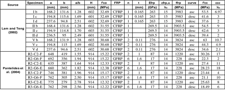
A test database containing a total of 17 FRP-confined elliptical concrete specimens has therefore been assembled and presented below in Table 2.1.
These test data cover elliptical specimens with section depth ranging from 95 to 775 mm, aspect ratio between 1.28 to 2.78 and height from 601 to 914 mm.
The unconfined concrete strengths of these specimens range from 12.22 to 32.69 MPa. Lateral confinement of these specimens was provided by Carbon FRP (C-FRP), 1 or 2 layers, for 13 specimens and by Glass FRP (G-FRP), 6 layers, for 4 specimens, where the FRP details were given by the manufacturers. All the test specimens failed by the rupture of FRP.
A commonly accepted value of 0.002 was used for the strain at the unconfined concrete strength , in arriving at the normalized ultimate axial strain of confined concrete.
Both specimens with ascending and descending branch are included in this database, because one of the main aim is to evaluate the sufficient level of the FRP confinement.
18
Specimen a b a/b H f'co FRP n t Efrp ɛfrp,u ffrp curve f'cc ɛcc
(mm) (mm) (mm) (MPa) (mm) (GPa) ‰ (MPa) (MPa) ‰
I b 168.2 131.6 1.28 602 32.69 CFRP 1 0.165 263 15 3983 asc 53.5 6.97 I c 194.8 115.6 1.69 601 32.69 CFRP 1 0.165 263 15 3983 desc 41.6 3 I d 237.6 94.8 2.51 602 32.69 CFRP 1 0.165 263 15 3983 desc 37.6 2 II b 168.4 131.6 1.28 602 31.55 CFRP 1 269.5 14 3903.5 asc 54.5 9 II c 194.9 114.8 1.70 603 31.55 CFRP 1 269.5 14 3903.5 desc 42.6 3 II d 236.5 95 2.49 601 31.55 CFRP 1 269.5 14 3903.5 desc 39.4 2 V b 168.2 131.9 1.28 603 30.68 CFRP 2 0.11 276 14 3824 asc 63 10.7 V c 194.8 115 1.69 602 30.68 CFRP 2 0.11 276 14 3824 asc 44.3 4.9 V d 237.6 94.6 2.51 602 30.68 CFRP 2 0.11 276 14 3824 desc 34.6 2.1 R2-C2-F 648 419 1.55 914 15.22 CFRP 2 1 87 14 1220 asc 30.26 17 R2-G6-F 692 356 1.94 914 15.22 GFRP 6 1.6 17 14 228 desc 22.3 2 R2-C2-E 635 387 1.64 914 12.33 CFRP 2 1 87 14 1220 asc 27.4 11 R2-G6-E 660 362 1.82 914 12.38 GFRP 6 1.6 17 14 228 asc 28.23 18 R3-C2-F 746 381 1.96 914 15.17 CFRP 2 1 87 14 1220 desc 23.44 4 R3-G6-F 762 305 2.50 914 15.17 GFRP 6 1.6 17 14 228 asc 21.1 10 R3-C2-E 775 279 2.78 914 12.32 CFRP 2 1 87 14 1220 asc 25.63 8 R3-G6-E 762 298 2.56 914 12.22 GFRP 6 1.6 17 14 228 desc 18.49 6 Source
Lam and Teng (2002)
Pantelides et al. (2004)
19
2.3 Theoretical models for FRP-confined elliptical concrete columns
2.2.2 Equation for compressive strength by Lam and Teng (2002)
With regard to the concrete in an FRP-wrapped elliptical specimen, at moment of failure, the compressive stress in the concrete varies over the specimen section, and the confinement effect is reduced if compared to a circular section. Indeed it is very well known that in the case of FRP-wrapped circular specimens the concrete is uniformly confined.
Below an expression of the compressive strength of FRP-confined concrete in an elliptical specimen is proposed, defined as the average axial stress at the peak load as it is commonly accepted, given by an equation analogous to the following equation:
where is referred to as the effective confinement ratio. The effective confining pressure can be defined as:
where = shape factor accounting for the effect of section shape and = confining
pressure in an equivalent circular column.
The equivalent circular column is defined here as one with the same FRP volumetric ratio as the elliptical column. Thus, the lateral confining pressure provided by FRP in the equivalent circular column can be evaluated using the following equation:
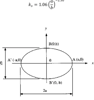
20 with the FRP volumetric ratio now given by:
All the properties and dimensions of the ellipse, as a and b, are reported in Fig. 2.1. For the FRP-wrapped elliptical specimens of this study, the value of the shape factor for each specimen can be found using equations 2.1 and 2.2, by making use of =0.67 and =3.71. Moreover, as one of the several results of Lam and Teng’s research work, it can be seen that the shape factor depends strongly on the major-to-minor axis length ratio of the elliptical section; for this reason the relationship between the shape factor and the a/b ratio based on the measured dimensions is found to be:
21
For practical use, the following simpler relationship is recommended:
For design purposes, Equation 2.6 should be combined with Lam and Teng’s proposal for the compressive strength of FRP-confined concrete, which is given by the following equation:
with =2, as their proposal reflects very closely the best-fit relationship of a large number of tests on circular columns. Consequently, for design use, the compressive strength of FRP-confined concrete in elliptical columns is proposed to be given by:
22
2.2.3 Stress-strain model proposed by Pantelides et al. (2004)
A very simple summary of the stress-strain model of Pantelides et al. is reported below; it focuses in particular on the compressive strength equation and the strain equation.
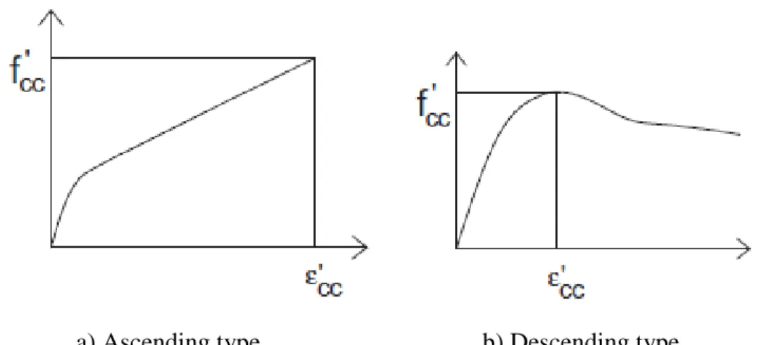
The present work, realized by Pantelides et al. in 2004, is built on the plasticity approach based on the five parameter Willam and Warnke model (1975), which was used to obtain the axial strength of FRP-confined concrete. For FRP-confined concrete with hardening behavior shown in Fig. 2.2a, the axial strength is given by the following equation: ; where
is the effective confinement ratio, or the maximum confining pressure
provided by the FRP jacket or post-tensioned FRP shell relative to the average unconfined concrete strength . The maximum confining pressure is obtained when the FRP jacket strain reaches its ultimate or rupture strain as follows:
where is the ultimate tensile strain of the FRP composite, is the modulus of elasticity of the FRP composite, is the volumetric ratio of the FRP jacket defined
as the ratio of the product of the circumference times the thickness of the jacket to the area enclosed by the jacket; k is the confinement effectiveness coefficient given as:
23
where is the shape factor which relates the effectively confined concrete area to the total cross-sectional area, is the post-tensioning factor which accounts for the contribution of the post-tensioning effect caused by dilation of the expansive cement concrete, and is the jacket efficiency factor which accounts for the fact that the ultimate FRP jacket hoop strains at failure were always lower than the full hoop tensile strength of the FRP composite, because of biaxial stress effects. The jacket efficiency factor is related to the friction between concrete and the FRP composite laminate, as well as the FRP jacket bond type and cross-sectional geometry. In addition, the strain distribution over the circumference of a circular jacket is consistent and uniform, while a large non-uniformity of strain distribution was observed in non-circular jackets. The jacket efficiency factor is defined as the ratio of FRP tensile hoop strain at rupture in the column tests, , to the ultimate tensile strain from FRP tensile coupon tests, , or = .
The effective confinement ratio is related to the axial strength because it includes shape, jacket efficiency, and post-tensioning effects, which influence confinement stiffness.
a) Ascending type b) Descending type
24 For
softening behavior is likely to result as shown in Fig. 2.2b, and the axial
strength is given by the equation below:
;
The axial strain in the FRP-confined concrete is given by one of three expressions,
depending on the type of confinement (bonded FRP jackets versus post-tensioned FRP shells) and confinement effectiveness (hardening versus softening behavior).
Thus, for concrete confined with externally bonded FRP jackets and hardening behavior (i.e.
), the axial strain is provided by:
where = initial elastic modulus of FRP-confined concrete and β is a normalizing constant that was derived from the elastic modulus degradation theory, proposed by Pantazopoulou and Mills (1995), expressed empirically in the following equationas a function of the jacket effective confinement ratio:
For concrete confined with externally bonded FRP jackets and softening behavior (i.e.
, the axial strain corresponding to is written as follows:
25
For circular and elliptical columns with post-tensioned FRP shells, the axial strain corresponding to is given by the following equation:
;
where = jacket efficiency factor, obtained empirically as 0.4 for circular and 0.3 for elliptical post-tensioned specimens; γ is a constant relating the volumetric to axial strain, expressed empirically above in Equation as a function of the effective confinement ratio.
An incremental approach, using the equations reported above, was described in the research work conducted by Yan, Z. and Pantelides, C.P (2006),in order to obtain the complete stress–strain behavior of FRP-confined concrete using a spreadsheet or computer program.
26
2.4 References
Pantelides, C.P., Yan, Z., and Reaveley, L.D. (2004), “Shape Modification of Rectangular Columns Confined with FRP Composites.” Report no. UT-05.03, University of Utah, Utah Teng, J.G., and Lam, L. (2002), “Compressive Behavior of Carbon Fiber Reinforced Polymer-Confined Concrete in Elliptical Columns.” Journal of Structural Engineering
Yan, Z., and Pantelides, C.P. (2010), “Concrete Column Shape Modification with FRP Shells and Expansive Cement Concrete.” Construction and Building Materials
Lam, L., and Teng, J.G. (2003), “Design-Oriented Stress-Strain Model for FRP-Confined Concrete in Rectangular Columns.” Journal of Reinforced Plastics and Composites
Jiang, T. (2008), “FRP-confined RC columns: Analysis, behavior and design” Dissertation for Doctor in Philosophy, Hong Kong Polytechnic University
Saenz, N. and Pantelides, C. P. (2007), “Strain-Based Design Model for FRP-Confined Concrete Columns.” Journal of Structural Engineering
Yan, Z., Pantelides, C.P., and Reaveley, L.D. (2007), “Post-tensioned FRP Composites Shells for Concrete Confinement.” Journal of Composites for Construction
Willam, K.J. and Warnke, E.P. (1975), “Constitutive model for the triaxial behavior of concrete.” Journal of Structural Engineering
Yan, Z. and Pantelides, C.P (2006), “Fiber-reinforced polymer jacketed and shape-modified compression members: II – model.” ACI Journal of Structural Engineering
Pantazopoulou, S.J. and Mills, R.H. (1995), “Micro-structural aspects of the mechanical response of plain concrete.” ACI Mate
27
CHAPTER 3
EXPERIMENTAL PROGRAM
3.1 Introduction
Since the database previously mentioned in Table 2.1 is clearly too small to conduct a serious and scientific study on FRP-confined elliptical concrete columns, it has been necessary to design and carry out a new experimental work.
In this chapter all the steps, from the design of the samples to the testing of the specimens, are reported and precisely described. Specimens’ preparation, instrumentation and test procedure constitute the content of this section and the main work of this research experience.
All these tests were conducted at the Hong Kong Polytechnic University.
They were realized under standardized conditions and all information and data used for assessing the models can be readily and accurately extracted.
28
3.2 Experimental test program
3.2.1 Design of the experimental work
The design of the experimental work was realized considering different variables: the aspect ratio a/b, that is the ratio between mayor and minor axis, the number of layer of CFRP, for evaluating the different level of confinement, and the cylinder strength of concrete fc, for studying the behavior of different kind of concrete.
A total of 32 specimens was produced, divided into eight batches of concrete. Each batch was composed by four designed specimens, two standard cylinders (152 mm of diameter and 305 mm of height) wrapped by FRP, two control cylinders and three cubes (150x150x150 mm).
The dimensions of the specimens were chosen first according to the size of the MTS machine; secondly using a constant ratio between the height of the specimen and the major axis H/a. All the specimens had a height of 400 mm and a major axis of 200 mm. Thus the constant ratio H/a=2 ensures that the specimens may not suffer from buckling problems due to slenderness. Therefore the only geometric variable was the minor axis b. Accordingly, giving different values to the aspect ratio a/b (1.0, 1.3, 1.7 and 2.0), the minor axis b had respectively the following theoretical values of 200, 153.8, 117.6 and 100 mm. One of the main aims of this study is to evaluate the capacity of the FRP-confined concrete columns by making the section more and more elliptical.
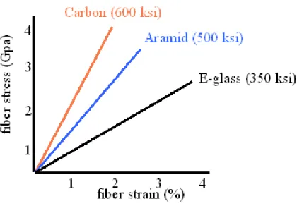
As it is well recognized, the general properties of Carbon FRP are quite different from those belonging to the Glass FRP. It can be seen from Fig. 3.1 that, although GFRP presents a larger capacity in terms of deformation, CFRP has nominal tensile strength significantly bigger than that one of GFRP. For this reason, CFRP was chosen for the present work.
29
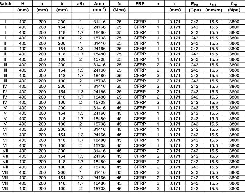
Batch H a b a/b Area fc FRP n t Efrp ɛfrp ffrp
(mm) (mm) (mm) (mm2) (Mpa) (mm) (Gpa) (mm/m) (Mpa)
I 400 200 200 1 31416 25 CFRP 1 0.171 242 15.5 3800 I 400 200 154 1.3 24166 25 CFRP 1 0.171 242 15.5 3800 I 400 200 118 1.7 18480 25 CFRP 1 0.171 242 15.5 3800 I 400 200 100 2 15708 25 CFRP 1 0.171 242 15.5 3800 II 400 200 200 1 31416 25 CFRP 1 0.171 242 15.5 3800 II 400 200 154 1.3 24166 25 CFRP 1 0.171 242 15.5 3800 II 400 200 118 1.7 18480 25 CFRP 1 0.171 242 15.5 3800 II 400 200 100 2 15708 25 CFRP 1 0.171 242 15.5 3800 III 400 200 200 1 31416 25 CFRP 2 0.171 242 15.5 3800 III 400 200 154 1.3 24166 25 CFRP 2 0.171 242 15.5 3800 III 400 200 118 1.7 18480 25 CFRP 2 0.171 242 15.5 3800 III 400 200 100 2 15708 25 CFRP 2 0.171 242 15.5 3800 IV 400 200 200 1 31416 25 CFRP 2 0.171 242 15.5 3800 IV 400 200 154 1.3 24166 25 CFRP 2 0.171 242 15.5 3800 IV 400 200 118 1.7 18480 25 CFRP 2 0.171 242 15.5 3800 IV 400 200 100 2 15708 25 CFRP 2 0.171 242 15.5 3800 V 400 200 200 1 31416 45 CFRP 1 0.171 242 15.5 3800 V 400 200 154 1.3 24166 45 CFRP 1 0.171 242 15.5 3800 V 400 200 118 1.7 18480 45 CFRP 1 0.171 242 15.5 3800 V 400 200 100 2 15708 45 CFRP 1 0.171 242 15.5 3800 VI 400 200 200 1 31416 45 CFRP 1 0.171 242 15.5 3800 VI 400 200 154 1.3 24166 45 CFRP 1 0.171 242 15.5 3800 VI 400 200 118 1.7 18480 45 CFRP 1 0.171 242 15.5 3800 VI 400 200 100 2 15708 45 CFRP 1 0.171 242 15.5 3800 VII 400 200 200 1 31416 45 CFRP 2 0.171 242 15.5 3800 VII 400 200 154 1.3 24166 45 CFRP 2 0.171 242 15.5 3800 VII 400 200 118 1.7 18480 45 CFRP 2 0.171 242 15.5 3800 VII 400 200 100 2 15708 45 CFRP 2 0.171 242 15.5 3800 VIII 400 200 200 1 31416 45 CFRP 2 0.171 242 15.5 3800 VIII 400 200 154 1.3 24166 45 CFRP 2 0.171 242 15.5 3800 VIII 400 200 118 1.7 18480 45 CFRP 2 0.171 242 15.5 3800 VIII 400 200 100 2 15708 45 CFRP 2 0.171 242 15.5 3800
30
Figure 3.1 – Typical FRP stress-strain curve
Furthermore, since the level of confinement is one of the main parameters in this research experience, as mentioned above, the specimens were subject to one or two layers of CFRP; in this way it becomes possible to identify an eventual threshold for the minimum amount for sufficient FRP confinement on the section. Thus, a series of parameters, including the effective confinement ratio, had been calculated during the design procedure for assessing the level of confinement.
All the details about the CFRP used in these experiments are reported in subsequent chapters.
A cylinder strength of concrete of 25 and 45 MPa had been designed. This is another important parameter closely related to the level of confinement; indeed, since the effective confinement ratio is the ratio between the effective confining pressure to the unconfined concrete strength, higher levels of nominal strength of concrete correspond to lower levels of confinement, given the same thickness and number of layers of FRP. The designed concrete mixtures for 25 MPa and 45 MPa concrete strength and the real amount of all the materials for composing the concrete are reported in the following chapter for every batch.
31
3.2.2 Specimens preparation
The preparation of all the 32 specimens followed a standard procedure, which is described below.
All the specimens were cast in steel formworks, shown in Fig. 3.2, previously cleaned and wet by a very thin layer of oil, so as to allow easier extraction of the concrete columns subsequently.
During the procedure of mixing the concrete, the standard Slump Test was carried out on a small amount of the mixture, as can be seen in Fig 3.3.
Then, once the test reached the acceptable value between 75-100 mm, the concrete was cast in the steel formworks and placed on a universal machine which provides vibrations (Fig. 3.4); this standard step minimizes the presence of bubble air and voids within the concrete cylinder.
32
Figure 3.2 – Steel formworks for two batches of concrete: a) all the steel formworks; b) circular formwork; c) elliptical formwork with aspect ratio a/b=1.3; d) elliptical formwork with aspect ratio a/b=1.7; e) elliptical formwork with aspect ratio a/b=2.0
33
Figure 3.4 – Vibrations procedure by using a standard machine
Thus the specimens were kept inside the steel formworks for between one or two days. Additionally, the concrete surfaces were watered in order to prevent shrinkage problems.
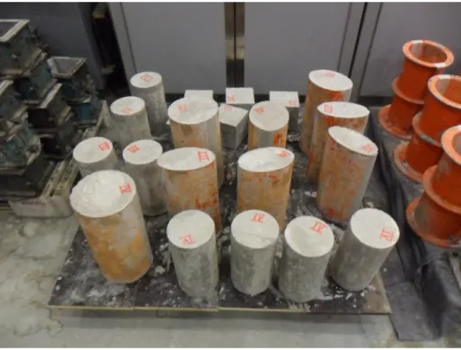
Once the concrete was completely hardened, the steel formworks were removed and the concrete cylinders were left for two weeks at the ambient temperature of the laboratory (Fig. 3.5).
34
Figure 3.5 – Specimens left to be cured at the temperature of laboratory
During this period, while the concrete reached a sufficient value of strength to undergo others procedures, all specimens were cured with water every day.
At the end of the two weeks the specimens were sanded with a grinder to remove the weaker external layer and to prevent dust sticking to the surface of the specimens. Then the epoxy putty was used for filling the holes presents on the surface of the specimens, as it is possible to see in Fig. 3.6; in this way a better bonding with the confining jacket was ensured.
35
Figure 3.6 – Specimens already sanded and treated by epoxy putty
After these procedures previously mentioned, the real dimensions of all the specimens were measured for scientific integrity a more scientific way of conducting this research work. This procedure was carried out by using a caliper, as shown in Fig. 3.7. The dimensions of each specimens, reported in the following chapter are given by the average value of the different measurements: for the height of the specimens, four measurements were taken at the four vertices. The widths of the section, major and minor axis were calculated for each specimen as the average value between the top and the bottom of the specimen.
Before the wrapping procedure, all the specimens were capped to ensure a smooth loading surface before testing and to provide a perfect vertical load. Indeed it is important to load the cylinder under an axial load for providing the best behavior and capacity of the specimens.
36
Dimensions of the section
b) Dimension of the height
Figure. 3.7 – Procedure of taking the dimensions by using the caliper
Two standard capping procedures were used by the author.
The first procedure provided the cooking of the capping material until the material reached the appropriate temperature; then the material was put into a steel mold, with
37
the appropriate shape for the specimens. Thus it was necessary to put the specimens into the mold immediately, before the material becomes hardened (Fig. 3.8a and Fig. 3.8b). During this step it is absolutely important to ensure that the longitudinal surface of the specimen was perfectly attached to the steel vertical bars of the mold; this device assures that the capping is perfectly realized.
38
The specimens is placed into the mold
The second procedure consists in using a pink material with high strength, a glass plate and a bubble level ruler, which ensures the perpendicularity of the plate on the surface of the specimens. Indeed the first step is to mix the pink powder with the water, following the proportions given by the manufactures. After mixing the material, the capping material was placed on the surface of the specimen. Thus the glass plate, previously cleaned and dried, is applied to the surface, spreading the capping material, as uniformly as possible, on the section. At the same time, the bubble level ruler was placed on the glass plate in order to allow calibration of the glass plate as perfectly horizontal (Fig. 3.8c). Then it is necessary to wait until the capping material becomes hardened.
39
The second way of capping procedure
Figure 3.8 – Capping procedure
This second procedure was applied when the first one failed after the wrapping procedure; indeed, although the capping material is stronger than the concrete, it is, at the same time, very brittle and subject to breakage.
Afterwards the FRP-jackets, all composed by the Carbon Fiber, were formed via the wet lay-up process. A layer of resin was first applied to the surface of the concrete core (Fig. 3.9a) and followed by the wrapping of the fiber sheets, which had already been saturated by the resin. The wrapping of fiber sheets was continuous, overlapping the starting end by 150 mm (Fig. 3.9b, Fig. 3.9c).
The length of the overlapping zone is closely related to the thickness of the sheet of CFRP. In this case, where the thickness of the C-FPR is 0.171 mm, the appropriate length for the overlapping zone is 150 mm. Thicker CFRP layer corresponds to a longer overlapping zone.
40
Surface of the specimens
41
Wrapping to the column
42
Since the width of a single sheet available (300 mm) to the writer was not sufficient to cover the entire height of a specimen, two separate sheets were used for the upper and lower parts of each specimen, respectively, without overlapping at the circumferential seam. This can be seen in Fig 3.9d.
Furthermore it should be noted that all the fiber sheets had fibers oriented only in hoop direction.
Application of plastic sheet
Figure 3.9 – Wrapping procedure
In addition, two FRP strips of 25 mm in width, with a length equal to two layers of FRP, were wrapped at the top and at the bottom of the specimens to prevent possible premature failure there.
Thus a plastic sheet was used to expel the air voids and redundant resin to ensure a compact bond between the concrete core and the confining jacket (Fig. 3.9e). This
43
procedure also smoothes the surface of the FRP jacket, making the installation of strain gauges easier.
3.2.2.1 Strain gauges and LVDT’s preparation and disposition
First of all, it is necessary briefly to describe the preparation procedure of the strain gauges.
There are different techniques to attach the strain gauges on the specimens, and in this report a summary of the main steps and elements is presented.
The strain gauge (Fig. 3.10a) needs to be attached to the terminals, which are produced by melting a steel wire (Fig. 3.10b and Fig. 3.10c). Then the assembled product is connected to the specimen by using an appropriate glue, and to the data log by the wires.
The final product is shown in Fig. 3.10d.
44
Preparation of the terminals
The terminals are attached to the strain gauges
The final product, ready to be installed on the specimen
45
Having described the strain gauges’ preparation, it is now necessary to present the strain gauges and LVDT’s layout among the lateral and longitudinal surface of the specimens.
- Hoop Strain Gauges – This kind of strain gauges measures the strain in hoop direction, allowing an understanding of the behavior of the columns around the section, and thus the identification of localizing the region of the specimens in which rupture occurs.
As regards the control cylinder, two lateral strain gauges, with a gauge length of 50 mm, positioned on the middle height, were placed 180° apart. In this case the cylinders without FRP, i.e. the control cylinders, had a different gauge length. Indeed all the specimens with FRP had strain gauges of only 20 mm of length. The different gauge length is due to the surface; indeed, notwithstanding the CFRP, the concrete did not behave uniformly. For this reason it became necessary to cover a longer region of surface on the plain concrete to allow a more accurate and reasonable reading of the strain (this was the case for the control cylinder).
On the other hand, the cylinder of 300 mm of height, wrapped by C-FRP, had six hoop strain gauges: four positioned at the four vertices, two installed 45° apart on the opposite side of the overlapping zone, in the manner shown in Fig.
For the columns with a/b=1, that is the circular section, a total of eight lateral strain gauges were installed on the surface of the specimens: four positioned at the four vertices of the section, two 45° apart on the opposite side of the overlapping zone and others two installed 30° apart on the same side of the overlapping zone. Thus one strain gauge was nearer the beginning of the overlapping zone, while the other was nearer the end.
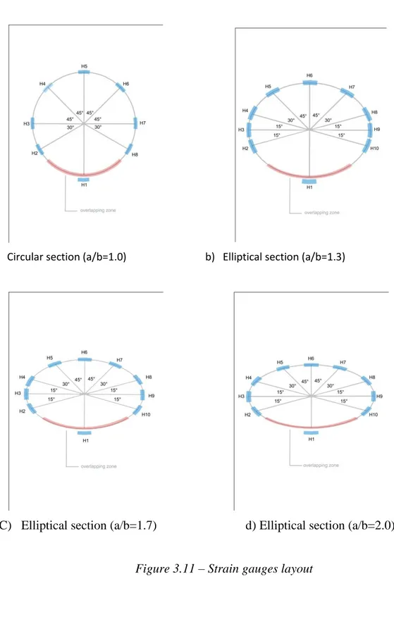
For all the FRP-confined concrete columns with elliptical section, a total of 10 lateral strain gauges were installed on the vertical surface of the columns; four hoop strain gauges were installed at the four vertices of the section; the others six strain gauges were installed according to the disposition shown in the Fig. 3.11. On the same side of the overlapping zone two strain gauges are positioned 15° apart from the vertices. On
46
Circular section (a/b=1.0) b) Elliptical section (a/b=1.3)
C) Elliptical section (a/b=1.7) d) Elliptical section (a/b=2.0)
Figure 3.11 – Strain gauges layout
the opposite side two strain gauges were positioned on half section 15° and 45° apart from the vertices.
47
In some cases it is not possible to install all the strain gauges due to imperfections arising during the earlier stages of work.
- Axial Strain Gauges – For each specimen, four longitudinal strain gauges, with a gauge length of 100 mm for the control cylinder and of 20 mm for every cylinder wrapped by FRP, were placed 90° apart on each of four vertices of the section.
All of the axial strain gauges were installed at the mid-height of the specimens. In this way, it is possible more precisely to align the specimens during the testing procedure, improving loading conditions. Additionally the presence of axial strain gauges may represent an alternative way of reading the axial strain apart from that given by the LDVT’s.
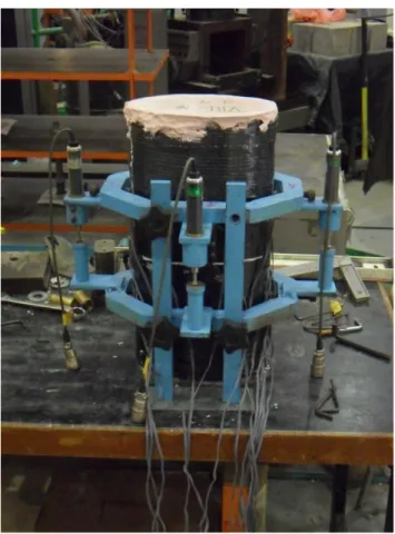
- LDVT’s – These instruments are the primary means of measuring axial strain. Two linear variable displacements transducers (LVDT) were positioned at 180° apart on the cylinder with height of 300 mm, while four LVDT’s were installed on the columns with height of 400 mm on each of the four vertices of the. The LVDT’s were installed on the specimen through an appropriate steel cage, as shown in Fig. 3.12.
48
Figure 3.12 – LVDT’s installation
Therefore, since the axial strain is very important in terms of stress-strain behavior, it is possible to have a comparison between the reading offered by the strain gauges and that one given by the LVDT’s, obtaining therefore a more reliable interpretation of the test results.
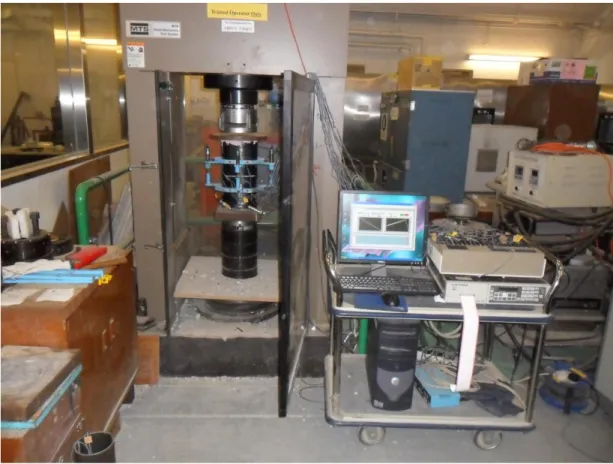
3.2.3 Instrumentation and Test
As mentioned above, all the specimens were tested under axial compression using a universal MTS machine, as shown in Fig. 3.13.
As mentioned above, a steel cage, on which the LVDT’s were installed (Fig. 3.12), was applied to each specimen. Then the specimen was placed in the MTS machine and the wires were connected to the data log. Afterwards a series of attempts of alignment
49
had been performed; a pre-load of 100 or 200 KN was applied to the specimen. Thus, by reading the values of the four axial strain gauges, it was possible to check whether or not the specimen was properly in the middle of the machine, that is under a perfect axial load.
All the specimens were tested with displacement control, at a constant rate of 0.18 mm/min for the cylinder with a height of 300 mm and 0.24 mm/min for the specimens with a height of 400 mm.
Usually, for the bigger specimens, an additional steel plate was used on the top of the columns with the aim of distributing evenly the load on the surface of the specimens. All test data, including the readings of the axial load, strain gauges and LVDTs were collected with the data logger and simultaneously saved into a computer.
50
3.3 Material properties
3.3.1 Concrete
Two nominal concrete compressive strength of 25 and 45 MPa for the entire test program were considered appropriate for evaluating the effectiveness of FRP confinement.
For this reason 4 batches were designed with a mix proportion of 25 MPa and the other 4 with a mix proportion of 45 MPa.
The designed concrete mix proportion for 25 Mpa had the following amounts: Portland cement 338.7 kg/m3, sand 715 kg/m3, water 210 kg/m3, aggregates (10 mm)
429 and aggregates (20mm) 643.
On the other hand the designed concrete mix proportion for 45 MPa had the following components: Portland cement 420.0 kg/m3, sand 688 kg/m3, water 210 kg/m3,
aggregates (10 mm) 413 and aggregates (20mm) 619.
These two theoretical designed mix proportions, designed for 1 cubic meter of concrete, assumed the following values of Water Absorption (defined as the moisture content at Saturated Surface Dried condition): Sand 1.1%, Aggregates (10 mm) 0.9% and Aggregates (20 mm) 0.8%.
For discovering the real content of water inside the components, a sample of all the elements (sand, aggregates 10 and 20 mm) was placed inside an oven at the temperature of 105 for 24 hours.
After calculating the content of water from the difference between the previous wet weight and the actual dried weight, it was possible to correct the proportions with new real values. A list of the real amount used for mixing every batch of concrete, is reported below in Table 3.1.
Standard concrete cylinders 152×305 mm and standard cubes 150x150x150 mm were prepared and cured under the same conditions of the specimens. These cylinders and cubes were tested at the corresponding age at which the related specimens were tested.
51
The cubes were firstly measured and then tested in a different universal machine, shown in Fig. 3.14.
BATCH
sand 10mm 20mm water cement sand 10mm 20mm
1 7.85 0.18 0.16 12.7 25.4 57.2 31.9 47.9 2 7.85 0.18 0.16 12.7 25.4 57.2 31.9 47.9 3 5.48 0.66 0.29 13.8 25.4 55.9 32.1 48 4 1.67 0.66 0.29 15.8 25.4 53.9 32.1 48 5 10.16 0.5 0.21 11.5 31.5 56.2 30.9 46.2 6 4.71 0.5 0.21 14.3 31.5 53.4 30.9 46.2 7 8.35 1.55 0.73 11.9 31.5 55.3 31.2 46.4 8 8.4 1.55 0.73 11.9 31.5 55.3 31.2 46.4
MC (%) REAL AMMOUNT (kg) for 0.075 m3
Table 3.2 – Values of Moisture Content and amount of the elements for mixing every batch of concrete
52
It is necessary to say that the nominal strength of concrete considered in all the present work, is the average value between the two peak strengths of the control cylinders, taking into account however the strengths of the cubes.
3.3.2 Carbon FRP (CFRP)
Unidirectional CFRP sheets of one-ply and two-ply nominal thickness tf of 0.171 mm were the wrapping material used for the entire research project.
Since all the standard tests were conducted several times on this kind of CFRP in the Hong Kong Polytechnic Laboratory, the mechanical properties provided by the manufacture were considered in light of the test results.
This characterization yielded an ultimate tensile strain efu of 1.55%, an ultimate tensile strength ffu of 3800 MPa and a modulus of elasticity Ef of 242 GPa.
All these parameters are reported and summarized below in Table 3.2.
53
3.4 References
Jiang, T. (2008), “FRP-confined RC columns: Analysis, behavior and design” Dissertation for Doctor in Philosophy, Hong Kong Polytechnic University
Lam, L., and Teng, J.G. (2003), “Design-Oriented Stress-Strain Model for FRP-Confined Concrete in Rectangular Columns.” Journal of Reinforced Plastics and Composites
Lam, L., and Teng, J.G. (2003), “Design-Oriented Stress-Strain Model for FRP-Confined Concrete.” Construction and Building Materials
Pantelides, C.P., Yan, Z., and Reaveley, L.D. (2004), “Shape Modification of Rectangular Columns Confined with FRP Composites.” Report no. UT-05.03, University of Utah, Utah Rocca, S. (2007), “Experimental and Analytical Evaluation of FRP Confined Large Size Reinforced Concrete Columns.” Dissertation for Doctor in Philosophy, University of Missouri-Rolla
Teng, J. G., Chen, J. F., Smith, S. T. and Lam, L. (2002), “FRP Strengthened RC Structures” Teng, J.G., and Lam, L. (2002), “Compressive Behavior of Carbon Fiber Reinforced Polymer-Confined Concrete in Elliptical Columns.” Journal of Structural Engineering
Youssef, M. N. (2003), “Stress-Strain Model for Concrete Confined by FRP Composites.” Dissertation for Doctor of Philosophy, Univeristy of California, Irvine
54
CHAPTER 4
EXPERIMENTAL RESULTS AND COMPARISON WITH
EXISITING MODELS
4.1 Introduction
This chapter presents and discusses the test results of the specimens described in Chapter 3. The axial stress-strain is the main instrument in investigating the behavior of confined concrete structures. Accordingly, a simple description of the trend of compressive strength and axial strain is also reported below.
Another important parameter for assessing the behavior of the specimens is the failure mode. An analysis of the hoop strain and a short report on the photographs of the broken specimens, with rupture zones marked, present the specimens’ behavior so as to provide a more global comprehension of the phenomenon.
4.1.2 Test results database
A summary of the test results is reported in the table below.
For every batch the nominal strength of concrete fc is the average value of the compressive strength (that is the ratio between the peak load to the section of the specimen) reached by the two control cylinders.
The corresponding strain εco at the unconfined concrete strength, in this case considered as the previously mentioned fc, has a commonly accepted value of 0.002.
55
The axial strain corresponding to the compressive strength, εcc , or the axial strain
corresponding to the ultimate point, εcu , is given by the average value of the four LVDT’s.
The hoop strain corresponding to the rupture of the specimen, εh,rup , is given by the average value of all hoop strain gauges.
56
batch a/b H a b fc
(mm) (mm) (mm) Mpa n t Efrp ɛfrp Ffrp fcc fcu ecc ecu eh,rup
(mm) (Gpa) ‰ (Mpa) (Mpa) (Mpa) ‰ ‰ ‰
I 1 402.2 200.4 200.4 32.55 1 0.171 242 15.5 3800 43.42 7.6 7.2 I 1.3 401.6 202.8 155.9 32.55 1 0.171 242 15.5 3800 42.88 10.8 7.6 I 1.7 400.6 200.6 120.0 32.55 1 0.171 242 15.5 3800 37.83 33.69 6.5 7.9 4.8 I 2 400.1 202.3 102.2 32.55 1 0.171 242 15.5 3800 35.47 5 II 1 400.3 199.7 199.7 32.64 1 0.171 242 15.5 3800 43.50 11.7 8.9 II 1.3 398.8 201.0 154.7 32.64 1 0.171 242 15.5 3800 40.21 39.38 9.9 10.1 6.3 II 1.7 400.6 200.1 120.8 32.64 1 0.171 242 15.5 3800 43.73 14.7 8.2 II 2 398.9 201.7 101.9 32.64 1 0.171 242 15.5 3800 40.52 11.9 5.8 III 1 400.9 200.0 200.0 35.69 2 0.171 242 15.5 3800 58.98 19 8.9 III 1.3 398.5 202.9 156.0 35.69 2 0.171 242 15.5 3800 48.22 47.98 12.9 13.6 4.6 III 1.7 399.7 200.8 120.2 35.69 2 0.171 242 15.5 3800 57.22 56.66 17.4 17.5 6.8 III 2 399.5 202.9 102.1 35.69 2 0.171 242 15.5 3800 43.23 41.3 10.9 15.7 4.8 IV 1 399.8 201.1 201.1 35.92 2 0.171 242 15.5 3800 53.32 12.6 5.9 IV 1.3 397.9 200.7 155.4 35.92 2 0.171 242 15.5 3800 56.30 12.7 6.7 IV 1.7 399.4 199.9 120.9 35.92 2 0.171 242 15.5 3800 59.42 17.1 7.1 IV 2 399.2 200.3 101.9 35.92 2 0.171 242 15.5 3800 46.34 11.9 5.2 V 1 404.4 200.2 200.2 44.91 1 0.171 242 15.5 3800 52.29 8.6 8.9 V 1.3 406.7 203.2 156.7 44.91 1 0.171 242 15.5 3800 51.06 9.8 7.2 V 1.7 401.8 201.0 120.1 44.91 1 0.171 242 15.5 3800 49.69 43.4 8.6 10.4 7.4 V 2 403.7 202.1 102.3 44.91 1 0.171 242 15.5 3800 48.07 41.92 7 9.3 4.9 VI 1 403.0 200.1 200.1 47.80 1 0.171 242 15.5 3800 52.91 8.4 7.8 VI 1.3 400.9 201.3 155.0 47.80 1 0.171 242 15.5 3800 52.50 9.4 6.8 VI 1.7 403.0 200.0 121.1 47.80 1 0.171 242 15.5 3800 51.14 8.5 6.2 VI 2 404.6 200.5 102.2 47.80 1 0.171 242 15.5 3800 46.82 36.12 4.3 5.8 3.4 VII 1 400.6 200.3 200.3 40.60 2 0.171 242 15.5 3800 57.82 10.6 6.6 VII 1.3 400.3 203.5 156.4 40.60 2 0.171 242 15.5 3800 59.14 13.11 7.6 VII 1.7 399.6 200.6 120.3 40.60 2 0.171 242 15.5 3800 58.95 15.7 7.3 VII 2 399.4 202.3 102.1 40.60 2 0.171 242 15.5 3800 50.84 50.67 11.7 13.8 5.2 VIII 1 401.7 200.1 200.1 42.53 2 0.171 242 15.5 3800 63.98 13.6 8.2 VIII 1.3 401.1 201.7 154.7 42.53 2 0.171 242 15.5 3800 59.58 11.8 6.4 VIII 1.7 400.9 200.0 121.1 42.53 2 0.171 242 15.5 3800 54.26 9.9 4.4 VIII 2 400.6 200.6 102.0 42.53 2 0.171 242 15.5 3800 52.01 49.37 8.7 12.8 4.9
CARBON FRP TEST RESULTS
57
4.2 Compressive Strength
As mentioned above, fcc represents the compressive strength at the peak point of the stress-strain behavior of the specimens.
In other words, this values represents the maximum strength capacity of the specimens.
It is also necessary to divide this parameter by the nominal strength of concrete, that is the cylinder strength, to underline the real benefit given by the FRP-confinement. Previous research carried out by the authors mentioned in Chapter 2, demonstrates that the compressive strength is strictly related to the aspect ratio, that is the ratio between the major and minor axis of the section of the specimens.
The following graph illustrates this relationship:
Figure 4.1 – Relationship between the strengthening ratio and the aspect ratio
As the graph shows, the strengthening ratio decreases, while the aspect ratio increases. This simple diagram the general trend, that is the compressive strength of
FRP-0.00 0.20 0.40 0.60 0.80 1.00 1.20 1.40 1.60 1.80 0.00 0.50 1.00 1.50 2.00 2.50 fcc /fc a/b
58
confined specimens, i.e. the effectiveness of the FRP-confinement to the concrete specimen, decreases with an increasingly elliptical section.
At the same time we can see from the plot that all the specimens present an enhancement of strength, except one, the elliptical specimen of the Batch VI with aspect ratio equal to 2. This may have been caused by some mistakes or imperfections, like a load eccentricity, occurred while preparing and testing this specimen.
For validating what has been said above, it is interesting to note that for the specimens belonging to the first and the last batch (I and VIII), which were wrapped with respectively 1 and 2 layers of C-FRP, the compressive strength of the specimens with a nominal a/b ratio of 2.0 was around 82% of that of the circular specimen.
Moreover it is also very interesting to analyze the effectiveness of the FRP-confinement, when the number of layers of C-FRP and the concrete cylinder strength are varied.
For example, by making a comparison between the V batch and VIII, which present almost identical cylinder strength values (respectively of 44.91 and 42.53 Mpa), it is possible to observe a significant enhancement of strength, if the number of the layers increases. The improvement ranges from 15% between the two elliptical specimens with a nominal aspect ratio of 2.0, to almost 30% between the two circular specimens. This also means that the enhancement of strength given by a greater number of layers is more effective for circular columns than for elliptical ones.
a/b f'cc (V) f'cc(VIII) percentage gap
(%)
1.0 1.16 1.50 29.3
1.3 1.14 1.40 22.8
1.7 1.11 1.28 15.3
2.0 1.07 1.22 14.0
59
Lastly it has been demonstrated that the effectiveness given by the FRP-confinement decreases as the cylinder strength increases. A comparison between the first and fifth batch shows that the confinement ratio of the specimens with a nominal aspect ratio of 1.0 and 1.3 is around 87%, while the two most elliptical specimens show a reduced gap, around 95%.
60
4.3 Ultimate Axial Strain
It is well known that ultimate axial strain of concrete can be increased by FRP confinement and thus FRP confinement represents an effective measure for the seismic retrofit of structures. Existing works based on tests of FRP-confined circular concrete specimens have related the ultimate axial strain of FRP-confined concrete to the confinement ratio (Lam and Teng, 2002).
The relationship between the confinement ratio and the axial strain at the peak stress of confined concrete, normalized by the same strain of unconfined concrete, which is assumed to have the common value of 0.002, is reported below.
Figure 4.2 – Relationship between the normalized axial strain and the effective confinement ratio
An important parameter to evaluate whether the specimens shows a stress-strain curve with a descending or ascending branch could be the minimum amount of FRP. This is, in other words, the minimum value of the effective confinement ratio for
0.00 1.00 2.00 3.00 4.00 5.00 6.00 7.00 8.00 9.00 10.00 0.00 0.05 0.10 0.15 0.20 0.25 0.30 0.35 0.40 ecc/eco f'l/fco
61
which the specimen presents an ascending branch. For this kind of specimens the strain at the peak stress is also the ultimate axial strain, and this strain is seen to rise almost linearly with the effective confinement ratio.
62
4.4 Stress-strain behavior
This section will provide a summary of what has been previously said about the compressive strength and the axial strain. The following pages will report the axial stress-strain curves for each of the specimens are reported.
4.4.1 Shape of stress-strain curve
The stress-strain curve of the C-FRP wrapped specimens belonging to the first batch is reported in the figure below. The y-axis shows the load of the machine, while the x-axis shows the axial strain represented by the average value of the LVDT’s reading.
Figure 4.3 – Stress-strain curves of the first batch
This figure shows that bilinear stress–strain relationships are clearly visible in specimens with an aspect ratio of 1.0 and 1.3, wrapped by one layer of CFRP, but not in elliptical specimens with higher a/b ratios.
0 200 400 600 800 1000 1200 1400 1600 1 101 201 301 401 501 601 701 801 901 1001 Serie2 Serie4 Serie6 Serie8 Circular Elliptical (a/b=1.3) Elliptical (a/b=1.7) Elliptical (a/b=2.0)