Alma Mater Studiorum – Università di Bologna
DOTTORATO DI RICERCA IN
INGEGNERIA CIVILE, CHIMICA, AMBIENTALE E DEI
MATERIALI
Ciclo XXIX
Settore Concorsuale di afferenza: 08/B2 Settore Scientifico disciplinare: ICAR/08
TITOLO TESI
Experimental Study of The Bond Behavior of Steel FRP-Concrete Joints
and Shear Behavior of Concrete Beams Reinforced With GFRP Bars
Presentata da: Imohamed Ali Omar Imohamed
Coordinatore Dottorato
Relatore
Luca Vittuari
Carloni Christian
For my beloved mother Azz Muftah and father Ali Omar, and all people that help and supported me.
Also to my ever supporting supervisor Prof. Christian Carloni
ACKNOWLEDGEMENT
I would like to thank all the parties who have given the co-operation to me in writing this thesis. I am sincerely great full to my supervisor, Prof. Christian Carloni for his continuous support and guidance in this thesis. He has set a high standard for the conduct of this study and his valuable suggestions and guidance have provided me the motivation needed to complete this thesis.
I would like to extend my thanks to my colleague, Mattia Santandrea for his supportive friendship during my PhD study.
I would also like to thank the staffs and technicians of the laboratory LISG (Laboratory of Structural and Geotechnical Engineering) at University of Bologna are gratefully acknowledged. Kerakoll S.p.A. of Sassuolo, Italy, is gratefully acknowledged for providing the composite materials.
Finally, I thank my family and friends for their supports and encouragement. Their encouragement provided the often-needed motivation and inspirations for me to push through the hard times. I would also like to acknowledge the contributions of those who have helped either directly or indirectly in the completion of this thesis.
Thank You.
TABLE OF CONTENTS TITLE ... i DEDICATION ... ii ACKNOWLEDGEMENT ... iii TABLE OF CONTENTS ... iv LIST OF TABLES ... xi
TABLE OF FIGURES ... xiii
TABLE OF APPENDICES ... xxi
CHAPTER 1: INTRODUCTION ... 1
1.0 Background of the study ... 1
1.1 Fibre Reinforced Polymer (FRP) ... 3
1.1.1 Carbon Fibre Reinforced Polymer (CFRP) ... 5
1.1.2 Aramid Fibre Reinforced Polymer (AFRP) ... 5
1.1.3 Glass Reinforced Polymer (GFRP) ... 5
1.2 Steel Fibers ... 6
1.3 Objectives of dissertation ... 7
1.4 Scope of dissertation ... 8
1.5 Outline of dissertation ... 9
1.6 References ... 10
CHAPTER 2: SHEAR BEHAVIOUR IN CONCRETE BEAMS REINFORCED WITH FRP BARS ... 12
1.0 Introduction ... 12
2.0 Shear in RC beams ... 13 iv
2.1 Shear in reinforced concrete beams without transverse reinforcement ... 13
2.1.1 Shear resistance mechanism... 13
2.1.1.1 Shear resistance of uncracked concrete, Vcz ... 14
2.1.1.2 Interface shear transfer, Va ... 15
2.1.1.3 Dowel action of longitudinal reinforcement, Vd ... 15
2.1.1.4 Arching action ... 15
2.1.1.5 Residual tensile stress across the inclined cracks, ft ... 16
2.1.2 Modes of failure ... 16
2.1.3 Factors affecting the shear strength of concrete ... 18
2.2 Shear design equation in the codes and guideline’s for FRP reinforced concrete members ... 18
2.2.1 American Concrete Institute (ACI) ... 19
2.2.2 Japan Society of Civil Engineers (JSCE) ... 19
2.2.3 Canadian Standard Association (CSA) ... 20
2.2.4 ISIS M03-07 Design Manual ... 21
3.0 Experimental program ... 22
3.1 Introduction ... 22
3.2 Detail of test specimens ... 23
3.3 Materials ... 27
3.3.1 Concrete ... 27
3.3.2 Reinforcements ... 29
3.4 Fabrication and curing practices ... 33
3.4.1 Formwork and reinforcement layout ... 33
3.4.2 Casting and curing beam ... 33
3.5 Test Procedure ... 34
4.0 Experimental results and analysis ... 35
4.1 Introduction ... 35
4.2 General behaviour ... 36
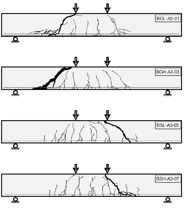
4.2.1 Crack patterns ... 36
4.2.2 Cracking loads ... 42
4.2.3 Load deflection behaviour ... 43
4.2.4 Failure modes ... 44
4.3 Analysis of test data ... 50
4.3.1 Shear strength ... 50
4.3.2 Effect of main variables ... 51
4.3.2.1 Effect shear span-to-depth ratio, a/d... 51
4.3.2.2 Effect of reinforcement ratio, ρ ... 51
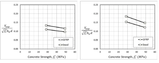
4.3.2.3 Effect of Concrete Compressive Strength, 𝑓𝑓𝑐𝑐′ ... 52
4.4 Comparison of experimental results with major design equations ... 54
4.4.1 Introduction ... 54
4.4.2 Comparison of the results ... 54
5.0 Conclusions ... 59
5.0 Recommendation... 60
6.0 References ... 61
CHAPTER 3: DEBONDING PHENOMENON, OF FRP COMPOSITES APPLIED TO A CONCRETE SURFACE, A STATE-OF-THE ART ... 64
1.0 Introduction ... 64
2.0 Failure modes in FRP-concrete bond system ... 65
3.0 Test setups and methods ... 67
4.0 Bond stress-slip relationship ... 72
5.0 Current bond-slip models ... 73 vi
5.1 Empirical models ... 75
5.1.1 De Lorenzis et al. (2001) ... 76
5.1.2 Chen and Teng (2001) ... 76
5.1.3 Dai et al. (2005) ... 77
5.2 Fracture mechanics based models ... 77
5.2.1 Täljsten (1996) ... 79
5.2.2 Neubauer and Rostásy (1999) ... 80
5.2.3 Brosens and Van Gemert (1999) ... 82
5.2.4 Brosens (2001) ... 84
5.2.5 Nakabaet. al. (2001) ... 86
5.2.6 Savioa et al. (2003) ... 88
5.2.7 Monti et al. (2003) ... 88
5.2.8 Dai and Ueda (2003) ... 89
5.3 Finite Element Models ... 90
5.4 Conclusions of bond–slip models ... 92
6.0 Previous research (experimental test programs and variability) ... 95
7.0 Parametric study of the bond strength ... 106
7.1 Concrete strength ... 106
7.2 Concrete surface preparation ... 106
7.3 Adhesive properties ... 107
7.4 Stiffness of FRP sheets ... 108
7.5 Effective bond length ... 108
7.6 Interfacial Fracture Energy ... 109
8.0 Conclusions based on previous research ... 110
9.0 References ... 111
CHAPTER 4: THE UNSOLVED ISSUES IN THE DESIGN PROCESS OF
FRP STRENGTHENED RC MEMBERS... 121
1.0 Introduction ... 121
2.0 Experimental investigation... 121
2.1 Experimental details and test setup ... 121
2.2 Direct shear test results ... 123
3.0 Cohesive Material Law (CML) ... 124
3.1 CML based on load responses ... 124
3.1.1 D’Ambrisi et al. (2012) ... 124
3.1.2 Dai et al. (2005) ... 125
3.2 Calibration method and construction of the analytical of the strain capacity (SC) response εmax(ℓ) ... 126
3.3 Construction of the analytical responses ... 126
3.4 Direct calibration of CML best on strain profile... 130
3.4.1 Dai et al. (2006) function ... 133
3.4.2 Sine function ... 133
3.4.3 Polynomial function ... 135
3.4.4 Bilinear function ... 137
5.0 Beams ... 139
6.0 Results and discussion ... 140
6.1 Calibrated CML functions for load responses ... 140
6.2 Comparison ... 141
7.0 Conclusions ... 144
8.0 References ... 144
CHAPTER 5: BOND BEHAVIOR OF STEEL-FIBER (SRP) COMPOSITES
APPLIED ONTO A CONCRETE SUBSTRATE ... 146
1.0 Introduction ... 146 2.0 Literature review ... 147 3.0 Experimental Program ... 151 3.1 Materials ... 151 3.1.1 Concrete ... 151 3.1.2 SRP Fiber ... 153 3.1.3 Adhesive ... 155
3.2 Test set-up’s and Methods ... 155
3.2.1 Single-lap shear test set-up (Method I)... 156
3.2.2 TPB test set-up (Method II) ... 159
4.0 Results ... 160
4.1 Failure modes ... 164
4.2 Strain analysis in direct-shear tests ... 166
4.3 Interfacial cohesive material law ... 169
5.0 Discussion ... 173
5.1 Fracture mechanics parameters ... 173
5.2 FRP-SFRP analogy ... 175
5.3 Influence of the bond set-up... 176
6.0 Conclusions ... 176
7.0 References ... 177
CHAPTER 6: A STUDY OF THE COMPRESSIVE BEHAVIOR OF CONCRETE COLUMNS CONFINED WITH STEEL-FRP JACKETS USING DIGITAL IMAGE ANALYSIS ... 181
6.0 Introduction ... 181 ix
6.1 Background ... 182
6.2 Experimental program ... 184
6.2.1 Materials ... 184
6.2.2 Methods ... 188
6.3 Results ... 192
6.3.1 Failure mode, Compressive strength, and Ultimate strain ... 192
6.3.2 Axial stress – Axial strain response ... 196
6.3.3 Steel-FRP jacket strains ... 199
6.4 Discussion ... 203
6.4.1 Influence of test variables ... 203
6.4.2 Ductility ... 205
6.4.3 Fracture Surface of Cross-Section ... 206
6.5 Conclusions ... 209
6.6 References ... 210
LIST OF TABLES
CHAPTER 1 ... 1
1.1 Mechanical properties for steel fibers (Kerakoll 2016) ... 6
CHAPTER 2 ... 12
2.1 Modes of failure due to shear ... 17
2.2 Detail of beam and test variables ... 25
2.3 Concrete mix design computation ... 28
2.4 Result of cube test ... 29
2.5 Geometrical characteristics of the GFRP test samples ... 31
2.6 Mechanical properties for GFRP bar ... 32
2.7 Mechanical properties for Mild Steel bar... 32
2.8 Experimental results ... 44
2.9 Axial stiffness of the reinforcing bars in different beams ... 45
2.10 Comparison of the experimental results with different design methods ... 56
CHAPTER 3 ... 64
3.1 Factors affecting the bond behaviour ... 64
3.2 Bond stress-slip relationship ... 93
CHAPTER 4 ... 121
4.1 Details about the specimen geometry and the test configuration considered for the calibration of the CML’s (Subramaniam et al. 2007) ... 122
4.2 Main parameters characterizing the CMLs ... 143
CHAPTER 5 ... 146
5.1 Material properties of SRP (Matana et. al, 2005) ... 148
5.2 Test results (SRP, 1-23 cords/in density) (Matana et. al, 2005) ... 148
5.3 Specimen data and key results from bond tests Mitolidis et al. (2008) ... 151
5.4 Properties of steel fibers provided by manufacturer (Kerakoll 2016)... 154
5.5 Mechanical properties of matrix by provided by manufacturer (Kerakoll 2016) ... 155
5.6 Test specimen characteristics (Direct-shear single lap test set-up) ... 158
5.7 Test Specimen Characteristics (TPB test set-up) ... 160
5.8 Test results (Direct-shear single lap test set-up) ... 162
5.9 Test results (TPB test set-up) ... 163
5.10 Fracture mechanics parameters ... 171
5.10 (cont.) Fracture mechanics parameters ... 172
CHAPTER 6 ... 181
6.1 Properties of steel fibers provided by manufacturer (Kerakoll S.p.A.) ... 187
6.2 Mechanical properties of matrix by provided by manufacturer (Kerakoll S.p.A.) ... 187
6.3 Test specimen characteristics ... 191
6.4 Summary of test results ... 195
TABLE OF FIGURES
CHAPTER 1 ... 1
1.1 Comparison among fiber, resin and composite tensile properties ... 3
1.2 (a) FRP rebars and (b) FRP sheets/laminates ... 4
1.3 Steel fiber sheets ... 6
1.4 Stress-strain characteristics of steel, FRP, SRP materials ... 7
CHAPTER 2 ... 12
2.1 Internal forces in a cracked beam without stirrups ... 14
2.2 Arch action in a beam (MacGregor and Bartlett 2000) ... 16
2.3 Summary of test parameters ... 23
2.4 The nomenclature of test specimen ... 24
2.5 Specimen geometry. ... 26
2.6 Relationship between the specimens ... 27
2.7 Concrete cube tests. ... 28
2.8 Different types of reinforcement used in this study ... 29
2.9 The experimental setup for GFRP bar testing ... 30
2.10 Typical GFRP bar tensile test specimen with end anchors ... 31
2.11 Stress-strain relationship of GFRP bar ... 32
2.12 Typical formwork and reinforcement layout ... 33
2.13 Curing process and removing the beams from the formworks ... 34
2.14 Schematic diagram of the test setup for the beam... 35
2.15 Test setup and cracks mapping ... 35
2.16 Typical formation of cracks in a beam during a test ... 37
2.17 Crack patterns for beams with different shear span-to-depth ratios ... 38 xiii
2.18 Crack patterns for normal strength concrete beams with different depths... 39
2.19 Crack patterns for beams with height equal to 150 mm ... 40
2.20 Crack patterns for beams with different concrete strengths and reinforcement ratio (ρf = 0.52%) ... 41
2.21 Crack patterns for beams with different concrete strengths and reinforcement ratio (ρf = 0.93%) ... 42
2.22 Typical load versus deflection curves (Beam BGH-A2-01) ... 45
2.23 Load-deflection behaviour of 150 mm thick beams in Group A1 ... 46
2.24 Load-deflection profile of beams in Group A2: (a) a/d = 2.5, and (b) a/d = 3.0 ... 47
2.25 Load-deflection behaviour of 250 mm thick beams with different concrete strengths and same reinforcement types and ratios in Group 4: (a) ρf = 0.52% (b) ρf = 0.93% ... 47
2.25 (cont.) Load-deflection behaviour of 250 mm thick beams with different concrete strengths and same reinforcement types and ratios in Group 4: (c) ρs = 0.52% and (d) ρs = 0.93% ... 48
2.26 Bond/anchorage failure of beam BGN-A2-02 ... 49
2.27 Failure pattern of beam BGN-A1-01 ... 49
2.28 Failure pattern of beam BGL-A3-02 ... 49
2.29 Effect a/d of experimental shear strength of beams in Group A2... 51
2.30 Effect of reinforcement ratio for 350 mm thick beams: (a) experimental shear strength, (b) normalized shear strength ... 52
2.31 Variation of normalized shear strength with respect to the cubic root of the axial stiffness ... 52
2.32 Effect of concrete compressive strength, experimental shear strength for 250 mm beams height with reinforcement ratios; (a) ρ = 52% and (b) ρ = 93%. .... 53
2.33 Normalized shear strength for 250 mm beams height with reinforcement ratios; (a) ρ = 52% and (b) ρ = 93% ... 53
2.34 Comparison of the experimental results with ISIS M03-07 predictions ... 57
2.35 Comparison of the experimental results with ACI 440.1R-06 predictions ... 57
2.36 Comparison of the experimental results with CSA S806-02 predictions ... 58
2.37 Comparison of the experimental results with JSCE (1997) predictions ... 58
CHAPTER 3 ... 64
3.1 Possible debonding locations ... 67
3.2 Illustrates the possible failure modes for strengthened flexural RC member ... 67
3.3 Double shear test (a) plan, (b) double shear push test, and (c) double shear pull test ... 69
3.4 Single shear test (a) plan, (b) Single shear push test, and (c) Single shear pull test ... 70
3.5 Beam Test... 71
3.6 Bond stress-slip relationship ... 72
3.6 (cont.) Bond stress-slip relationship ... 73
3.7 Local bond-slip curves reported in literature (a) Mazzotti et al. (2008) and (b) Liu and Wu (2012) ... 75
3.8 Bond-slip models for plate to concrete bonded joints, Yuan and Wu (1999) ... 79
3.9 Bond displacement curve of an adhesive joint based on nonlinear fracture mechanics, Täljsten (1996) ... 80
3.10 Idealized local bond low of Holzenkämpfer (1994) ... 81
3.11 Representative schematics of configurations of different layers used for the computation of bond slip (Brosens and Van Gemert 1999) ... 82
3.12 Representative schematics of configurations of different layers used for the computation of bond slip (Brosens 2001) ... 84
3.13 Mohr-coulomb failure criterion (Brosens 2001) ... 84
3.14 (a) Bi-linear Stress-Slip Relationship between Concrete and FRP and (b) Popvic's Expression Based Stress-Slip Relationship Concrete and FRP ... 87
3.15 Bond-slip curve for FRP-concrete interface obtained from CFJT-Plate
experimental data ... 88
3.16 Bond slip models suggested by Lu et al. (2005) ... 90
3.17 Bond-slip curves from existing bond-slip models (Lu et al. 2005)... 91
3.18 Single-lap shear bond test setup (Chajes et al. 1996)... 96
3.19 Sketch of the test equipment used in the tensile test series (Täljsten et al. 1997) ... 97
3.20 Shear test specimen (Brosens and Van Gemert 1997) ... 98
3.21 (a) Specimens, (b) Arrangement of strain gages (Maeda et al. 1997) ... 98
3.22 Schematic of strain distribution in CFS ... 99
3.23 Finite element mesh ... 99
3.24 (a) Specimen configuration, (b) Test Rig, Side and front view (Bizindavyi and Neale 1999) ... 100
3.25 Test specimen. (Note: 1 in. = 25.4 mm.) (De Lorenzis et al. 2001) ... 101
3.26 (a) Test specimen, (b) Data acquisition sketch (Nakaba et al. 2001) ... 102
3.27 Shear-slip model for bonded concrete joints, Chen and Teng (2001)... 103
3.28 Single and double shear tests: (a) Single shear test; (b) Double shear test and (c) Plan ... 103
3.29 Pullout test setup (Dai et al. 2005) ... 104
3.30 Test specimen (Yao et al. 2005) ... 105
3.31 Effects of the concrete Strength on interfacial fracture energy of the bond (Dai et al. 2005) ... 106
3.32 Effects of the adhesive properties on interfacial fracture energy of the bond (Dai et al. 2005) ... 107
3.33 Effects of FRP stiffness on interfacial fracture energy of the bond (Dai et al. 2005) ... 108
CHAPTER 4 ... 121
4.1 Specimen dimensions and loading arrangement (Subramaniam et al. 2007) ... 122
4.2 Typical load versus global slip response of the FRP bonded to concrete for test W_4 in Subramaniam et al. (2007) ... 123
4.3 Typical CML (D’Ambrisi et al. 2012) ... 125
4.4 Typical CML (Dai et al. 2005) ... 125
4.5 (a) Typical CML for an FRCM composite. (b) Strain profiles consequent to the typical CML. (c) Load response corresponding to the typical CML. (d) Joint and slip capacity responses corresponding to the typical CML ... 127
4.6 Typical CML (Bilinear function) ... 139
4.7 Interfacial crack in beam ... 139
4.8 The best fitting curve of the load responses of specimen W_4... 140
4.9 Bond stress-slip relationship between CFRP and concrete substrate: (a) all tested specimens Eq.( 2) and (b) all tested specimens Eq.( 3)... 141
4.10 Cohesive material law τ-s for specimen W_4 obtained using six different functions to fit experimental data. ... 141
4.11 S-shape εyy profile for specimen W_4 using four different functions to fit experimental data ... 142
CHAPTER 5 ... 146
5.1 Direct shear test setup (Matana et. al, 2005) ... 148
5.2 a) Scheme of shear test; b) photograph of test set sample (Figeys et al. 2005) .. 149
5.3 The SRP used in the experiments (Figeys et al. 2005) ... 149
5.4 Experimental set-up and configurations of representative specimens (Mitolidis et al. 2008) ... 150
5.5 Strength development of cubic and cylindrical specimens over time ... 152
5.6 a) and b) Experimental set-up for fracture mechanics tests for 150 mm width specimens. ... 153
5.7 a) P/b – δ response for 70 mm width specimens. b) P/b – δ response for
150 mm width specimens. ... 153
5.8 SRP Fiber (Kerakoll S.p.A.) ... 154
5.9 The SRP used in this work (Kerakoll S.p.A.) ... 154
5.10 The epoxy resin used in this work (Kerakoll S.p.A.) ... 155
5.11 Direct-shear single lap test set-up ... 158
5.12 TPB test set-up ... 159
5.13 a) Typical load-global slip response for SFRP. b) Load response for specimen DS_300_50_MD_ND_B_2. c) Load response for specimen DS_300_50_HD_D_S_5. d) Load response for specimen DS_300_50_HD_ND_B_1. e) Load response for specimen DS_300_50_UHD_ND_S_3. f) Load response for specimen DS_300_50_UHD_D_B_5. ... 161
5.14 Failure mode for specimen DS_300_50_UHD_D_B_3. ... 162
5.15 a) Load response for MD notched specimens tested in TPB. b) Load response for HD notched specimens tested in TPB. ... 163
5.16 a) Failure mode for specimen TPB_400_50_MD_B_1. b) Failure mode for specimen TPB_400_50_HD_B_1. ... 164
5.17 a) SFRP strip after debonding for specimen DS_300_50_MD_ND_B_3. b) SFRP strip after debonding for specimen DS_300_50_UHD_ND_S_2. ... 165
5.18 Failure mode for specimen TPB_400_50_MD_B_3 ... 166
5.19 a) Load response for specimen DS_300_50_UHD_D_B_5. b) S-shape εyy profile for specimen DS_300_50_UHD_D_B_5. ... 168
5.20 S-shape εyy profile for specimen DS_300_50_UHD_D_B_5 using three different functions to fit experimental data. ... 169
5.21 Cohesive material law τ-s for specimen DS_300_50_UHD_D_B_5 obtained using three different functions to fit experimental data. ... 170
5.22 Typical variation of strain as a function of x, for different locations along the bond length for specimen DS_300_50_UHD_D_B_5 ... 173
CHAPTER 6 ... 181
6.1 Concrete strength gain: (a) compressive strength; (b) tensile strength ... 184 6.2 Experimental set-up for fracture mechanics tests for 150 mm width prisms:
( photograph ) ... 185 6.2 (cont.) Experimental set-up for fracture mechanics tests for 150 mm width prisms
( Sketch ) ... 186 6.3 150 mm width prisms: (a) P/b – CMOD response; (b) P/b – δ response ... 186 6.4 70 mm width prisms: (a) P/b – CMOD response; (b) P/b – δ response ... 186 6.5 Specimen preparation: (a) application of matrix to concrete surface;
(b) application of steel fiber sheet around the prism; (c) application of external layer of matrix; (d) finished specimen ... 189 6.6 (a) Photo of specimen; (b) test setup ... 190 6.7 Failure mode of steel-FRP confined specimen (specimen
SQ-450-HD-CE-UT-S-1L-1 shown): (a) front face; (b) right face; (c) back face; (d) left face; (e) cut section ... 192 6.8 Axial stress - axial strain response determined by each LVDT for
representative specimens: (a) SQ-450-MD-CE-T-S-1L-2; (b) SQ-450-HD-CE-UT-S-1L-3 ... 196 6.9 Axial stress – axial strain response for specimens in: a) Groups 1 and 2; b)
Groups 1 and 3; c) Groups 3 and 4; d) Groups 4 and 5; e) Groups 5 and 6; f) Groups 5 and 7 ... 198 6.10 Comparison of axial stress – axial strain response determined by LVDTs
and DIC (specimen SQ-450-HD-CE-T-R-1L-1) ... 200 6.11 Representation of the eight squares used to calculate the values of the
strain using DIC technique: (a) axial strain; (b) hoop strain ... 200 6.12 Axial stress – strain response determined by DIC for confined specimens:
(a) Group 1; (b) Group 2; (c) Group 3; (d) Group 4; (e) Group 5; (f) Group 6; (g) Group 7. ... 202 6.13 Average Atotal/Apeak for each group ... 206
6.14 Photos of cut cross-sections after failure: (a) SQ-450-HD-CE-UT-S-1L-1; (b) SQ-450-HD-CE-UT-R-1L-3. ... 207
6.15 Variation of the ratio: a) 𝑓𝑓′�����𝑐𝑐𝑐𝑐 𝑓𝑓′𝑐𝑐𝑐𝑐 �����
� ; and b) 𝑓𝑓′�����𝑐𝑐𝑐𝑐 𝑓𝑓′𝑐𝑐𝑐𝑐,𝑆𝑆 �������
� with respect to corner
radius ratio 2r/b... 208
TABLE OF APPENDICES
APPENDIX TITLE ... PAGE
I Photographs of the failure mode of all beams ... 213 II Photographs of the experimental program of debonding
investigation in chapter 5 ... 216
CHAPTER 1
INTRODUCTION
1.0 Background of Study
Corrosion of the reinforcement is the main reason for deterioration of reinforced concrete (RC) structures with conventional steel. Corrosion is generally associated with the reduction of the effective area of the reinforcement causing a decrease of the strength and stiffness of the reinforcement and, consequently, of the RC element. In order to restore existing buildings that suffer deterioration problems, in the last few decades new strengthening materials, known as fiber reinforced polymer (FRP) composites, gained a wide diffusion all over the world. FRP composite materials are employed in all those applications related to strengthening and rehabilitation of existing concrete structures. FRPs have several advantages if compared to traditional strengthening materials that can be summarized as follow: high strength to weight ratio, corrosion resistance, ease of handling and installation, and design and construction flexibility. The application of FRP materials in civil engineering is worldwide recognized. Various organizations in countries such as United States, Canada, Great Britain, Japan, and Italy released design guidelines, recommendations, and standards related to FRP composites.
FRP composites consist of high strength fibers embedded in an organic matrix. Different types of fibers are available, such as carbon (CFRP), aramid (AFRP), glass (GFRP), and steel (SRP). Fibers are commercially available in the form of plates/sheets or bundles (used as external reinforcement) and bars (used as internal reinforcement).
The use FRP plates/sheets externally bonded to existing concrete elements has steadily emerged, over last three decades, as an efficient technique for structural rehabilitation, repair and strengthening of deteriorated and deficient concrete
components and systems, as highlighted from Karbhari et al. (2006), and Meier (1995). FRP composites have successfully been used for strengthening of reinforced concrete (RC) structures as pointed out from Teng et al. (2002).
The use of internally FRP reinforcement bars as an alternative to steel reinforcement bars in concrete structures has been accepted in construction industry mainly due to their excellent electrochemical corrosion resistance and high mechanical performances. FRP reinforcement bars can be used as longitudinal and shear reinforcement. However, some properties of FRP reinforcement, such as its brittleness, could have adverse effects on its performance as reinforcement for concrete members. Since GFRP is more economical balance of cost and strength properties than other available FRP (CFRP and AFRP), it is more attractive for infrastructure application and has been used as reinforcement in concrete beams, bridges and slabs for more than twenty years (Benmokrane et al. 2006). GFRP has more resistance to corrosion and higher tensile resistance compared to steel (Newhook et al. 2002). Therefore, the present study discusses mainly in chapter 2 on the behaviour of beams reinforced internally with GFRP reinforcement bars.
A steel reinforced polymer (SRP) system was also tested as part of this research in chapter 4 and 5. SRPs are made with high-strength twisted steel wires embedded in an epoxy matrix. SRPs have several benefits over traditional FRP materials including lower cost, better fire resistance, and compatibility with anchorage systems.
Since GFRP and SRP are newly developed strengthening materials, a better understanding of the mechanical behaviour of these composite systems is needed. The current research is mainly focused on the following aspects: the use of GFRP bars as internal reinforcement for simply supported concrete beams as reported in Chapter 2 and the use of SRP system externally for debonding and confinement investigation as reported in chapter 5 and 6.
1.1 Fibre Reinforced Polymer (FRP)
Fiber reinforced polymers (FRP) are a particular typology of composite materials, made of high resistance fibers impregnated with polymeric resins. The mixing result is a material with properties between fiber and resin Figure 1.1.
Figure 1.1: Comparison among fiber, resin and composite tensile properties
FRP materials are characterized by excellent tensile strength in the direction of the fibers and by negligible strength in the direction transverse to the fibers; this illustrates the anisotropic nature of these materials. FRP composites do not exhibit yielding, but instead are elastic up to failure and they are also characterized by relatively low modulus of elasticity in tension and low compressive properties.
Their function usually consists in adsorbing tensile stress due to shear and flexural actions. Often, among the several advantages, it can be listed also the increase of the overall stiffness and ductility.
FRP properties make these materials particularly suitable for structural applications, especially in support or substitution of steel. The general advantages of FRP reinforcement compared to steel are:
• Durability in aggressive environments • High strength-to-density ratio
• Magnetic and electric neutrality • Low specific weight
• Low axial coefficient of thermal expansion
Without underlining the importance of a lower installation cost, the use of FRP composites possesses some advantages compared to traditional retrofitting methods; as an example, the disturbance of both occupants and facilities are minimal and there is no loss of valuable space. In addition, from the structural point of view, the dynamic properties of the structure remain unchanged because there is no addition of weight that would lead to increase the seismic forces.
FRP products are commercialized in different shapes: rods, tendons, laminates and three-dimensional components.
FRP reinforcement comes in the shape of rods of circular cross-sections, strips of rectangular cross-sections, strands, and laminates, which enable different types of applications, as shown in Figure 1.2.
(a) (b) Figure 1.2: (a) FRP rebars and (b) FRP sheets/laminates
Generally, FRP can be classified into three types which are Glass Fiber Reinforced Polymer (GFRP), Carbon Fiber Reinforced Polymer (CFRP) and Aramid Fiber Reinforced Polymer (AFRP).
1.1.1 Carbon Fiber Reinforced Polymer (CFRP)
CFRP is a composite material which consists of carbon fibre and resins. CFRP is more expensive composite material, compared to GFRP and AFRP, but have some advantages, such as high strength, stiffness and most durable.
Although CFRP have many advantages compared to steel, such as lighter in weight and corrosion resistant materials, but cost of CFRP still remain as the issue of replace steel as reinforcement materials. Beside this, the brittle behaviour of CFRP is also one of the problem that been concerned.
1.1.2 Aramid Fiber Reinforced Polymer (AFRP)
AFRP is highly oriented organic fiber derived from polyamide incorporating into aromatic ring structure.
AFRP offers excellent impact resistance, good electric and temperature insulating properties and they are also resistant to organic solvents, fuels and lubricants. AFRP have a medium modulus and a very low density as compared to GFRP and CFRP. It is available in tows, yarns and various woven cloth products.
1.1.3 Glass Fiber Reinforced Polymer (GFRP)
Fiber drawn from an inorganic product of fusion that has cooled without crystallizing. GFRP produces a common, low cost reinforcing fiber, but they weight more than CFRP or AFRP and the lower modulus requires special design treatment where stiffness is critical. Glass has been the predominant fiber for many civil engineering applications because of an economical balance of cost and specific strength properties.
The two types of glass fibres most commonly used are E-glass and S-glass. E-glass has the lowest cost of all commercially available reinforcing fibres, and is used for general purposes where strength, electrical resistance, acid resistance, and low cost are important. S-glass has higher strength, stiffness and ultimate strain than E-glass, but is more expensive, and more susceptible to degradation in alkaline environments than E-glass (Benmokrane et.al, 1995).
1.2 Steel Fibers
High strength steel fibers have recently been introduced as an alternative to FRPs such as carbon fiber reinforced polymer (CFRP) (Prota et al., 2006).
It made of high strength twisted steel wires impregnated with epoxy resin, in the case of steel reinforced polymer (SRP), or with cementitious, in the case of steel reinforced grout (SRG) systems.
The advantages of using these materials over FRPs, among them, the material cost is relatively, and SRP have some inherent ductility (Casadei et al., 2005). However, the application method for FRPs and SRP/SRG composite sheets for strengthening concrete/masonry structures are same.
Figure 1.3: Steel fiber sheets
Table 1.1. Mechanical properties for steel fibers (Kerakoll 2016). Density of steel fibers weight [g/m2] no cords/mm Break Deformation [%] Tensile Strength [MPa] Modulus [GPa] Equivalt thickness t* [mm] Medium density (MD) 1200 0.314 > 2 > 3000 > 190 0.168 High density (HD) 2000 0.472 > 2 > 3000 > 190 0.254 Ultra-High Density (UHD) 3300 0.709 > 2 > 3000 > 190 0.381 6
The stress versus strain behavior of some typical FRP and SRP materials are presented in Figure 1.4. Also shown in the figure are the traditional building materials used in tension: mild steel reinforcing and high strength steel used in prestressing strands.
Figure 1.4 Stress-strain characteristics of steel, FRP, SRP materials
1.3 Objectives of dissertation
The objective of this research program is to investigate a number of issues related to glass fiber reinforced polymer (GFRP) bars, and steel reinforced polymer (SRP) composite strips.
1. To investigate the shear strength of concrete beams reinforced with glass fiber reinforced polymer GFRP bars.
2. To investigate the debonding mechanism between steel reinforced polymer (SRP) composites strips and the concrete surface, using two different set-up; concrete specimens were tested using the single-lap shear test set-up and specimens were tested using a three-point bending set-up, and compare the results obtained based on two different test set-ups.
3. To investigate the behavior of short concrete prisms with a square cross-section confined by steel reinforced polymer (SRP) composite strips.
1.4 Scope of dissertation
A total of 96 concrete (beams, prisms) were tested in the course of this research; 14 as part of a shear strength of concrete beam reinforced with GFRP bar Study, 7 as part of the Debonding Phenomenon Study, 19 as part of the Bond Study, 31 as part of the Fracture Mechanics Study and 25 as part of the Confinement Study.
The Shear Strength Study, whose experimental program is described in Chapter 2 of this dissertation, examined the shear behavior of simply supported concrete beams reinforced with longitudinally GFRP bars. The variables examined in the experimental program included the GFRP longitudinal reinforcement ratio and the concrete strength.
The Bond Study, A state-of-the art was compiled and an indirect calibration of the Mode-II cohesive law for CFRP sheets bonded to concrete surface, described in Chapter 3 of this dissertation.
The Bond Study, deals with the debonding phenomenon, a better understanding of FRP-concrete bond behavior assessing some of the common cohesive material law (CML) relationship on the basis of the results of an experimental program conducted by Subramaniam et al. (2007),described in Chapter 4.
The Bond Study (SRP) using the single-lap shear test set-up, whose experimental program is described in Chapter 5 of this dissertation, the bond behaviour of SRP composite strips externally bonded to a concrete substrate was investigated, 99 specimens were tested. The variables examined included the bonded length, bonded widths, loading rate and density of SRP composite.
The Bond Study (SRP) using the three-point bending set-up, whose experimental program is described in Chapter 5 as well, of this dissertation, 6 specimens were tested to analyze the debonding mechanism between SRP composite strips and the concrete surface. The variable examined was density of SRP composite.
The Confinement Study, whose experimental program is described in Chapter 6, examined the effectiveness of concrete compressive members confined by SRP composites in terms of load-bearing capacity and ultimate strain with respect to unconfined prisms. The variables examined included the density of steel fibers, concrete corner condition, concrete surface treatment, FRP jacket height, and number
of confinement layers. Digital image correlation (DIC) is used to qualitatively and quantitatively study the displacement and strain fields on the composite surface. The Fracture Mechanics Study, using the three-point bending set-up, whose experimental program is described in Chapter 5 also of this dissertation, 31 specimens with different sizes cast from the same concrete used for confined specimens were tested to evaluate the fracture energy of concrete. All concrete prisms had a central notch with a V-shaped tip.
1.5 Outline of dissertation
This dissertation is divided into six chapters. The following is a brief description of each chapter's content:
Chapter One of the dissertation, presented an introduction, including an overview on FRP and SRP composites, the main characteristics and various applications of both composite. The objectives, scope and outline of the research project are also included in this chapter.
Chapter Two of the dissertation, deals with the experimental campaign to study the shear strength of GFRP longitudinally reinforced concrete beams without shear reinforcement. All beams were simply supported and subjected to two point loads and known as four point bending test. It was analyzed the behavior of beams, such as failure load, failure mode, cracking load, crack patterns, deflections. Moreover, experimental results are compared using the different analytical equations provided by the available design codes for FRP reinforcement.
Chapter Three of the dissertation, deals with the debonding phenomenon, of fiber reinforced polymer (FRP) composites applied to a concrete surface. A state-of-the art was compiled and a indirect calibration of the Mode-II cohesive law was attempted.
Chapter Four of the dissertation, deals with the debonding phenomenon, a better understanding of FRP-concrete bond behavior assessing some of the common CML or bond-slip (τ-s) relationship on the basis of the results of an experimental program conducted by Subramaniam et al. (2007).
Chapter Five of the dissertation, divided into two parts, and both part related to the debonding studies but with different methods. The first part, deals with an experimental
study using single-lap shear test set-up. The second part comprises, deals with an experimental study using three-point bending set-up and the test specimens had a central notch. Both methods performed to analyze the debonding mechanism of SRP composite strips applied onto a concrete substrate. For each test campaign describes the test set-up, test details and materials used. Furthermore, the results were reported and then compared. Chapter Six of the dissertation, presents an experimental study was carried out to understand the behavior of short concrete prisms with a square cross-section confined by SRP composite sheets embedded in an epoxy matrix subjected to a monotonic concentric compressive load. In additional, concrete prisms casted from the same concrete used for confined specimens were tested using a three point bending set-up to evaluate the fracture energy of concrete. All concrete prisms had a central notch with a V-shaped tip.
Each chapter consists of background information, literature review, details of the experimental program, design of the specimens test and a conclusion of the results obtained from the experiments and analyses with respect to the issues and observations discussed throughout the thesis, finally, references in each chapter separately.
1.6 References
Benmokrane B., Chaallal O. & Masmoudi R. (1995). “Glass fibre reinforced plastic (GFRP) rebars for concrete structures,” Constr. and Bldg. Mat., 9(6), pp 353–364 Benmokrane B, El-Salakawy E, El-Ragaby A, Lackey T. (2006). “Designing and testing of concrete bridge decks reinforced with glass FRP bars. J Bridge Eng 2006;11(2):217–29.
Casadei, P., Nanni, A., & Alkhrdaji, T. (2005). “Steel-reinforced polymer: An innovative and promising material for strengthening infrastructures.” Concrete Engineering International, 9(1), 54-56.
Karbhari, V. M., Niu, H., and Sikorsky, C., (2006). “Review and Comparison of Fracture Mechanics-Based Bond Strength Models For FRP-Strengthened Structures, Journal of Reinforced Plastics and Composites, Vol. 25, No. 17, 1757-1738.
Kerakoll S.p.A. - web site: <www.kerakoll.com> (accessed Jan 2016).
Meier u. (1995). “Strengthening of structures using carbon fibre/epoxy composites’, Construction and Building Materials, Vol. 9, No. 6, pp 341–351.
Newhook J., Ghali, A, and Tadros, G. (2002), "Concrete Flexural Members Reinforced Concrete with Fibre Reinforced Polymer: Design for Cracking and Defonnability," Canadian Journal of Civil Engineering, 29, pp. 125-134.
Prota, A., Tan, K. Y., Nanni, A., Pecce, M., & Manfredi, G. (2006). “Performance of shallow reinforced concrete beams with externally bonded steel-reinforced polymer. ACI structural journal, 103(2), 163.
Teng, J. G., Chen, J. F., Smith, S. T.and Lam, L. (2002). “FRP Strengthened RC Structures.” England: John Wiley& Sons, Ltd.
CHAPTER 2
SHEAR BEHAVIOUR IN CONCRETE BEAMS
REINFORCED WITH FRP BARS
1.0 Introduction
The use of fibre reinforced polymer (FRP) bars, as an alternative to steel reinforcement for reinforced concrete structures, is gaining acceptance among the structural engineers. These bars have some favorable properties than conventional steel bars; such as; corrosion resistance, high strength to weight ratio. longer durability and magnetic neutrality.
The behavior of reinforced concrete beams at failure in shear is distinctly different form their behavior in flexure (Nawy, E.D. 2003). A failure due to shear is sudden as compared to a failure due to flexure. This type of failure should be avoided in design of reinforced concrete structures. Due to the fact that FRP bars behave brittle type of rupture and low modulus of elasticity, and the shear strength of beams reinforced with GFRP bears have not been adequately studied (MacGregor, J. and Wright, J. K. 2005). The behavior of reinforced concrete beams reinforced with FRP bars failed in shear will become remarkable topics to investigate. In addition, although some equations for shear design have been provided in the most of the codes but not all of the behaviors of concrete beam reinforced with FRP bars have been covered especially on diagonal shear cracking load (Thamrin, R. et al. 2002).
There has been extensive research on the flexural behavior of FRP reinforced concrete members, and it has been well established that the flexural capacity of concrete members reinforced with FRP bars can be predicted by traditional beam theory (Faza and Gangarao 1993, Nanni 1993, ISIS 2001). In contrast, the shear behaviour of FRP reinforced concrete members is different from that of steel-reinforced concrete members due to their different properties; including the modulus of elasticity, E, surface characteristics, and bond characteristics. Several
studies on the shear capacity of FRP reinforced concrete members without shear reinforcement has indicated that the shear strength is influenced by the stiffness of the tensile reinforcement (Sonobe et al. 1997, Michaluk et al. 1998, Tureyen and Frosch 2002). In addition, the behaviour of FRPs is elastic-brittle with no yielding or ductility at failure and its modulus of elasticity is lower than that of steel. These characteristics make the shear behaviour of FRP reinforced concrete beams more complex. Therefore, it has been recognized that the shear behaviour of FRP reinforced concrete beams should be further investigated independently to reflect these specific material characteristics.
The focus of this research is to investigate the size effect of concrete beams reinforced with GFRP bars on its shear behaviour. A total of eighteen beams reinforced with longitudinal reinforcement. The main variables in this investigation were shear span-to-depth ratio (a/d), longitudinal reinforcement ratio (ρ), concrete compressive strength (𝑓𝑓𝑐𝑐′) and reinforcement type.
2.0 Shear in RC beams
2.1 Shear in reinforced concrete beams without transverse reinforcement
The shear strength of reinforced concrete beams without transverse reinforcement has generated a lot of research since the beginning of the last century. However, a clear understanding of shear behaviour of those beams is still limited. This is referred to the complexity of the affecting parameters that govern the shear strength of concrete beams without shear reinforcement. Many structural concrete members are constructed without transverse reinforcement such as slabs, footings, joists, and lightly stressed members.
2.1.1 Shear resistance mechanism
Shear transfer mechanisms in concrete beams are complex and difficult to identify clearly due to the complex stress redistributions that occur after cracking. Shear is transmitted between two planes in various ways in reinforced concrete members.
According to the ACI-ASCE committee 445 (1998) reported that after the formation of diagonal cracks in members without stirrups, shear is carried by concrete as a combination of five structural mechanisms as shown in Figure2.1:
(i) Shear resistance of uncracked concrete, Vcz (ii) Interface shear transfer, Va
(iii) Dowel action of longitudinal reinforcement, Vd (iv) Arching action
(v) Residual tensile stress across the inclined cracks, ft
Figure 2.1: Internal forces in a cracked beam without stirrups
2.1.1.1 Shear resistance of uncracked concrete, Vcz
This shear transfer mechanism occurs in uncracked members or in the uncracked portions of structural members. In an uncracked concrete member, the shear force is transferred by inclined principal tensile and compressive stresses.
Failure may occur by inclined cracking or crushing of the concrete depending on whether the tensile or compressive stresses reach the corresponding strength of concrete.
The shear force can be calculated by the integration of the shear stresses over the depth of the compression zone. Many researchers quantified the contribution of this shear mechanism is between 20% and 40% of the total shear force (ASCE-ACI 1973).
2.1.1.2 Interface shear transfer, Va
This shear transfer mechanism is based on the friction along the inclined crack interface, which develops due to the relative slip between the two surfaces of the crack. The crack passes though the aggregate or instead of around the aggregates, depending on the concrete strength and type. In normal strength concrete as the aggregates protruding from the crack surface provide resistance against slip, which is termed as aggregate interlock. In lightweight and high strength concrete, the cracks go through the aggregate rather than around the aggregate, it is still have the ability to transfer shear, in this case the shear is transferred by friction or interface shear. However, the term Friction or Interface Shear is more appropriate than aggregate interlock to describe this mechanism of shear transfer. Tests conducted to quantify the contribution of this mechanism indicated that between 33% and 50% of the total shear force on a beam may be carried by interface shear transfer (ASCE-ACI 1973).
2.1.1.3 Dowel action of longitudinal reinforcement, Vd
If the reinforcing bars cross a crack, shearing displacements along the crack will be resisted, in part, by a dowelling force in the bar. Dowel contribution is strongly dependent on the transverse rigidity and strength of the longitudinal bar.
Normally, dowel action is not very significant in beams without transverse reinforcement, the reason behind that is the maximum shear in a dowel is limited by the tensile strength of the concrete cover supporting the dowel. Dowel action may be significant in beams with large amounts of longitudinal reinforcement. Particularly when the longitudinal reinforcement is distributed in more than one layer (ASCE-ACI 1998). Many studies on dowel action indicated that the dowel shear force to the total shear force by about 15-25% (ASCE-ACI 1973).
2.1.1.4 Arching action
The arching action occurs in deep beams, or beams with shear span-to-depth ratio (a/d) having less than 2.5 (Razaqpur et al. 2004). For such members, a significant redistribution of internal forces can be expected after cracking, and the shear force can be transferred directly to the supports Figure 2.2. For arch action to develop, a horizontal reaction component is required at the base of the arch. In beams this is usually provided by the tie action of the longitudinal bars.
Figure 2.2: Arch action in a beam (MacGregor and Bartlett 2000)
2.1.1.5 Residual tensile stress across the inclined cracks, ft
When concrete is loaded in direct tension, there is an important descendent (softening) branch has been known when the peak tensile stress is reached for some time Gopalaratnam and Shah (1985). This softening branch is attributed to the residual tensile stress across the crack. Hence, small parts of concrete bridge the crack and continue to transmit a tensile force up to crack widths in the range of 0.05 to 0.15 mm (ASCE-ACI 1998).
Reineck (1991) has found that the shear stresses across inclined cracks can be related to the residual tensile stresses which provide a important portion of the shear resistance of very shallow members with depths less than about 100 mm, where the crack widths are small.
2.1.2 Modes of failure
For beams with low span-to-depth ratio or inadequate shear reinforcement, the failure can be due to shear. A failure due to shear is sudden as compared to a failure due to flexure.
The following five modes of failure due to shear are identified. 1) Diagonal tension failure
2) Shear compression failure 3) Shear tension failure 4) Web crushing failure 5) Arch rib failure
The occurrence of a mode of failure depends on the span-to-depth ratio, loading, cross-section of the beam, amount and anchorage of reinforcement. The following five modes of failure due to shear are identified and presented in Table 2.1.
Table 2.1: Modes of failure due to shear
Type Failure mode
Diagonal tension failure
In this mode, an inclined crack propagates rapidly due to inadequate shear reinforcement.
Shear compression failure
There is crushing of the concrete near the compression flange above the tip of the inclined crack.
Shear tension failure
Due to inadequate anchorage of the longitudinal bars, the diagonal cracks propagate horizontally along the bars.
Web crushing failure
The concrete in the web crushes due to inadequate web thickness.
Arch rib failure
For deep beams, the web may buckle and
subsequently crush. There can be anchorage failure or failure of the bearing.
2.1.3 Factors affecting the shear strength of concrete
Several analytical and experimental studies have revealed that the concrete contribution to the shear resistance (Vc) of beams without shear reinforcement is affected by some dominant parameters, Among them ASCE-ACI Committee 445 (1998):
1. Shear span-to-depth Ratio, a/d 2. Tensile strength of concrete, 𝑓𝑓𝑐𝑐′ 3. Longitudinal reinforcement ratio, ρ 4. Effective depth, d, (Size of beam) 5. Axial force
However, the significance of each parameter to the shear resistance (Vc) of beams without shear reinforcement is still under debate.
2.2 Shear design equation in the codes and guideline’s for FRP reinforced
concrete members
Shear design recommendations for FRP-reinforced concrete beams in current design codes adopt a similar approach as conventional steel reinforced concrete design methods. The nominal shear capacity ( Vn) of reinforced concrete beams is computed by:
Vn = Vc + Vs (2.1) where Vc is the shear strength of concrete beams and Vs is the shear resistance offered by shear reinforcement.
This section summarizes the design equations used to compute Vc as recommended by the American Concrete Institute (ACI) standard ACI 440.1R-06 (ACI 2006); Canadian Standards Association (CSA) standards CSA S806-02 (CSA 2002); the Japan Society of Civil Engineering (JSCE) standard (JSCE 1997) and Intelligent Sensing for Innovative Structures, Canadian Network of Excellence (ISIS 2007).
2.2.1 American Concrete Institute (ACI)
According to American Concrete Institute (ACI) committee 440, the shear design of FRP reinforced concrete is similar to that of steel reinforced concrete as given in ACI 318-08. However, the mechanical properties of FRP affect the shear strength with the main factors being the low FRP modulus of elasticity and low transverse shear strength of FRP. Using a model developed by Tureyen and Frosch (2003), the concrete shear capacity Vc , for flexural members with FRP as main reinforcement can be evaluated as follows:
𝑉𝑉𝑐𝑐 =25 �𝑓𝑓𝑐𝑐′𝑏𝑏𝑤𝑤𝑐𝑐 (2.2) where c is the cracked transformed section neutral axis depth, for singly reinforced, rectangular cross sections is given as:.
c = k d
The computation of the neutral axis depth k dependent on the flexural FRP reinforcement ratio and the ratio of the modulus of elasticity of the FRP reinforcement to the concrete, k is calculated as;
𝑘𝑘 = �2𝜌𝜌𝑓𝑓𝑛𝑛 + �𝜌𝜌𝑓𝑓𝑛𝑛�2− 𝜌𝜌𝑓𝑓𝑛𝑛
where 𝜌𝜌𝑓𝑓 being the flexural FRP reinforcement ratio, and 𝑛𝑛 = 𝐸𝐸𝑓𝑓/𝐸𝐸𝑐𝑐, where Ef and
Ec are the modulus of elasticity of FRP reinforcement and concrete, respectively; 𝑓𝑓𝑐𝑐′ is the specified compressive strength of concrete; bw is the web width; and d is the distance from the compression fiber to the centroid of the main tensile reinforcement.
2.2.2 Japan Society of Civil Engineers (JSCE)
The Japan Society of Civil Engineers (JSCE 1997) recommended the following expression for shear strength (Vc) of FRP reinforced concrete members:
𝑉𝑉𝑐𝑐 = 𝛽𝛽𝑑𝑑𝛽𝛽𝑝𝑝𝛽𝛽𝑛𝑛𝑓𝑓𝑣𝑣𝑐𝑐𝑑𝑑𝑏𝑏𝑤𝑤/𝛾𝛾𝑏𝑏 (2.3) where,
𝛽𝛽𝑑𝑑 = (1000/𝑑𝑑)1/4 ≤ 1.5
𝛽𝛽𝑝𝑝 = �100𝜌𝜌𝑓𝑓𝐸𝐸𝑓𝑓/𝐸𝐸𝑠𝑠�1/3 ≤ 1.5
𝛽𝛽𝑛𝑛 = 1 + 𝑀𝑀𝑐𝑐/𝑀𝑀𝑑𝑑 ≤ 2 𝐹𝐹𝐹𝐹𝐹𝐹 (𝑁𝑁𝑑𝑑′ ≥ 0) 𝛽𝛽𝑛𝑛 = 1 + 2𝑀𝑀𝑐𝑐/𝑀𝑀𝑑𝑑 ≥ 0 𝐹𝐹𝐹𝐹𝐹𝐹 (𝑁𝑁𝑑𝑑′ < 0) 𝑓𝑓𝑣𝑣𝑐𝑐𝑑𝑑 = 0.2(𝑓𝑓𝑐𝑐𝑑𝑑′ )1/3 ≤ 0.72
where 𝑓𝑓𝑐𝑐′ represents concrete strength, bw reflects effective web width, d reflects effective depth, Ef is modulus of elasticity of flexural FRP reinforcement and Es is modulus of elasticity of steel, ϒb is strength reduction factor, generally equal to 1.3,
Ma is decompression moment, Md is design bending moment, 𝑁𝑁𝑑𝑑′ is design axial compressive force, and βn equal to 1.0 for sections without axial force resultant. According to this code, the concrete contribution to the shear strength has a limiting value. Similar to the ACI (2006), this method does not include the effect of shear span-to-depth ratio (a/d), and if a section has no longitudinal reinforcement, the equation will give zero shear strength.
2.2.3 Canadian Standard Association (CSA)
According to the Canadian Standard Association (CSA-S806-02) Code. The shear strength of members having either at least the minimum amount of transverse reinforcement as specified by the CSA standard or an effective depth not exceeding 300 mm, the shear strength calculated as:
𝑉𝑉𝑐𝑐 = 0.035𝜆𝜆∅𝑐𝑐�𝑓𝑓𝑐𝑐′𝜌𝜌𝑓𝑓𝐸𝐸𝑓𝑓𝑀𝑀𝑉𝑉𝑓𝑓 𝑓𝑓𝑑𝑑�
1/3
𝑏𝑏𝑤𝑤𝑑𝑑 (2.4)
0.1𝜆𝜆∅𝑐𝑐�𝑓𝑓𝑐𝑐′𝑏𝑏𝑤𝑤𝑑𝑑 ≤ 𝑉𝑉𝑐𝑐 ≤ 0.2𝜆𝜆∅𝑐𝑐�𝑓𝑓𝑐𝑐′𝑏𝑏𝑤𝑤𝑑𝑑
where λ reflects the concrete density factor, ∅𝑐𝑐 represents the concrete material resistance factor, 𝑓𝑓𝑐𝑐′ represents concrete strength, bw reflects effective web width and
d reflects effective depth. The quantity�𝑉𝑉𝑓𝑓/𝑀𝑀𝑓𝑓�𝑑𝑑, is not to be taken as greater than
1.0. �𝑉𝑉𝑓𝑓/𝑀𝑀𝑓𝑓�𝑑𝑑 , is the value of the factored shear, Vf, divided by the factored 20
moment, Mf, at the section under consideration and is the inverse of the a/d ratio for a simply supported member. This equation considers the effect of axial stiffness (Ef ρf), shear span-to-depth ratio (a/d), and concrete compressive strength 𝑓𝑓𝑐𝑐′ for calculating the shear strength.
To account for the size effect for members having an effective depth exceeding 300 mm and with no transverse shear reinforcement or less transverse reinforcement than the minimum given by CSA standard, the value of Vc is calculated using:
𝑉𝑉𝑐𝑐 = �1000 + 𝑑𝑑� 𝜆𝜆∅130 𝑐𝑐�𝑓𝑓𝑐𝑐′𝑏𝑏𝑤𝑤𝑑𝑑 ≥ 0.08𝜆𝜆∅𝑐𝑐�𝑓𝑓𝑐𝑐′𝑏𝑏𝑤𝑤𝑑𝑑 (2.5)
This equation gives the concrete contribution to the shear strength of FRP reinforced concrete members regardless of the FRP reinforcement ratio or the FRP type, which is anomalous to the findings that the shear strength increases with an increase in the reinforcement ratio. Thus, the equation gives more conservative results for the beams with high axial stiffness ( Ef ρf ) of the longitudinal FRP bar (EI-Sayed et al. 2006). ln addition, the equation neglects the shear transfer by arch action and it is quite conservative for beams with a/d less than 2.5 (Razaqpur and Isgor 2006).
2.2.4 ISIS M03-07 Design Manual
Intelligent Sensing for Innovative Structures (ISIS) published a series of design manuals that address the production, testing, and use of FRP. Design Manual 03 (ISIS 2007) provides guidance for design of concrete structures internally reinforced with FRP. The shear design method for FRP reinforced members is based on the simplified method of CSA A23.3-94 code.
According to this method. The shear capacity of FRP reinforced concrete members containing no transverse web reinforcement and having an effective depth less than 300 mm is calculated as:
𝑉𝑉𝑐𝑐 = 0.2𝜆𝜆∅�𝑓𝑓𝑐𝑐′𝑏𝑏𝑤𝑤𝑑𝑑�𝐸𝐸𝐸𝐸𝑓𝑓
𝑠𝑠 (2.6) 21
where λ reflects the concrete density factor, ∅𝑐𝑐 represents the concrete material resistance factor, 𝑓𝑓𝑐𝑐′ represents concrete strength, bw reflects effective web width, d reflects effective depth, Ef is modulus of elasticity of flexural FRP reinforcement and
Es is modulus of elasticity of steel. For beams which have an effective depth greater than 300 mm, Vc , is taken as:
𝑉𝑉𝑐𝑐 = �1000 + 𝑑𝑑� 𝜆𝜆∅260 𝑐𝑐�𝑓𝑓𝑐𝑐′𝑏𝑏𝑤𝑤𝑑𝑑�𝐸𝐸𝐸𝐸𝑓𝑓
𝑠𝑠 (2.7)
The Equation 2.6 and Equation 2.7, the reduction in Vc , compared to the steel reinforced concrete is based on the ratio of the modulus of elasticity. However, this method does not consider the effect of shear span-to-depth ratio and longitudinal reinforcement ratio, which are believed to affect the shear strength.
3.0 Experimental program
3.1 Introduction
This research program a systematic experimental investigation was carried out to examine the effect of some of the parameters, discussed in Section 2.2.3, on the shear strength of Glass Fiber Reinforced Polymer (GFRP) reinforced concrete beams without transverse reinforcement. Besides, steel reinforced concrete beams are fabricated as the control beam to investigate the effect of the type of reinforcements. A summary of the test parameters investigated is shown in Figure 2 .3.
In this chapter, the details of the test specimens, materials and procedure used in the preparation of specimens, instrumentation of the test specimens, testing procedure and test set-up are discussed.
Figure 2.3: Summary of test parameters
3.2 Detail of test specimens
There are several structural members, such as retaining walls, foundation, upper and lower slabs of cut-and-cover tunnel and bridge deck, where shear reinforcement is not used. The specimens in the current research represent those members as well as beams and girders without transverse shear reinforcement. The main objective of the current research is to determine the concrete contribution to the shear strength. Eight concrete beams reinforced with GFRP bars and six control concrete beams reinforced with steel bars, were tested until failure. In order to realize the occurrence of shear failure, all tested beams were reinforced with longitudinal reinforcement only, its means, without shear reinforcement. All beams were simply supported and subjected to two point loads and known as four point bending test in laboratory. Based on the parameters investigated (Figure 2.3). The specimens were divided into three groups for GFRP reinforced beams. While, the steel reinforced concrete specimens were divided into two groups, since the effect of reinforcement ratio was not investigated for this type of reinforcement. Figure 2.6 shows the relationship between the specimens.
𝑓𝑓𝑐𝑐′ = 28.5 MPa for the "Low-strength"
𝑓𝑓𝑐𝑐′ = 33.5 MPa for the "Normal-strength"
𝑓𝑓𝑐𝑐′ = 49.1 MPa for the "High-strength"
Concrete strength 𝑓𝑓𝑐𝑐′ Shear span to depth a/d Reinforcement ratio ρ
DESIGN AND DETAILS OF THE BEAM SPECIMENS
Reinforcement type GFRP , Steel df = 10 mm df = 12 mm df = 16 mm
The available diameters and length of the GFRP bars
a/d = 2.5 a/d = 3.0 a/d = 3.1 ρ = 0.52% ρ = 0.91% ρ = 0.93% ρ = 1.27 % ρ = 2.29 % 23
The beams in Group A1 were designed to investigate the effect of the longitudinal reinforcement ratio. two sets of beams with 150 mm width, 150 mm height and 1000 mm length were reinforced only with GFRP reinforcements, the reinforcement ratio for this investigation were 1.27% and 2.29%.
To investigate a/d of normal strength concrete beams, four sets of beams were selected in Group A2. Two beams reinforced with GFRP reinforcement sized with same width of 130 mm and same high of 230 mm, but different lengths, which are 1500 mm and 1800 mm, it’s means, different a/d ratios, which are 2.5 and 3.0. Similarly, for other two beams reinforced with steel reinforcement.
The effect of concrete strength was investigated using the beams in Group A3. Eight sets of beams with 200 mm width, 250 mm height and 2000 mm length, four for beams reinforced with GFRP and four for beams reinforced with steel reinforcements, the concrete strengths for this investigation were, low strength concrete 28.5 MPa and high strength concrete 49.1 MPa.
The specimen identifications (IDs) as shown in Figure 2.4 were defined in the following manner. The first letter of the specimen ID was (B), all specimens started with this letter, which is first letter of (Beam). The second letter was for the type of reinforcement used (“G” for GFRP and “S” for Steel). This was followed by character for concrete compressive strength “L” for Low concrete strength, “N” for Normal concrete strength and “H” for High concrete strength, where the concrete compressive strength was followed by group numbers “A1” for group 1, “A2” for group 2 and “A3” for group 3. The last number was for the numbers followed in each group. The details of beams and test parameters that were used for the identifications of a specimen are highlighted in Table 2.2, and cross sections of specimens are shown in Figure 2.5.
Figure 2.4. The nomenclature of test specimen
B G N - A1 - 01
01 : Number of beam
A1: Group number (A1, A2 and A3)
N : Concrete strength 𝑓𝑓𝑐𝑐′ (N: Normal), (H: High) and (L: Low)
G : reinforcement type (GFRP: Glass fibre and S: Steel)
B : Beam
Table 2.2: Detail of beam and test variables G ro u p Bar Type Specimens ID fc' (MPa) bw (mm) h (mm) d (mm) a (mm) a/d m (mm) L (mm) Lh (mm) L Total (mm) Longitudinal Reinforcement Axial stiffness Af Ef (Nx106) Parameters investigated Bar No. db (mm) Af (mm2) ρ (%) A1 GFRP BGN-A1-01 33.5 150 150 119 300 2.50 220 820 90 1000 2 12 226.2 1.27 11.83 ρ BGN-A1-02 33.5 150 150 117 300 2.50 220 820 90 1000 2 16 402.1 2.29 22.81 ρ A2 GFRP BGN-A2-01 33.5 130 230 200 500 2.50 300 1300 100 1500 3 10 235.6 0.91 12.23 a/d BGN-A2-02 33.5 130 230 200 600 3.00 400 1600 100 1800 3 10 235.6 0.91 12.23 a/d
Steel BSN-A2-03 33.5 130 230 200 500 2.50 300 1300 100 1500 3 10 235.6 0.91 49.43 a/d BSN-A2-04 33.5 130 230 200 600 3.00 400 1600 100 1800 3 10 235.6 0.91 49.43 a/d A3 GFRP BGL-A3-01 28.5 200 250 219 670 3.10 350 1690 155 2000 2 12 226.2 0.52 11.83 ρ , 𝑓𝑓𝑐𝑐′ BGL-A3-02 28.5 200 250 217 670 3.10 350 1690 155 2000 2 16 402.1 0.93 22.81 ρ , 𝑓𝑓𝑐𝑐′ BGH-A3-03 49.1 200 250 219 670 3.10 350 1690 155 2000 2 12 226.2 0.52 11.83 𝑓𝑓𝑐𝑐′ BGH-A3-04 49.1 200 250 217 670 3.10 350 1690 155 2000 2 16 402.1 0.93 22.81 𝑓𝑓𝑐𝑐′ Steel BSL-A3-05 28.5 200 250 219 670 3.10 350 1690 155 2000 2 12 226.2 0.52 47.46 ρ , 𝑓𝑓𝑐𝑐′ BSL-A3-06 28.5 200 250 217 670 3.10 350 1690 155 2000 2 16 402.1 0.93 84.37 ρ , 𝑓𝑓𝑐𝑐′ BSH-A3-07 49.1 200 250 219 670 3.10 350 1690 155 2000 2 12 226.2 0.52 47.46 𝑓𝑓𝑐𝑐′ BSH-A3-08 49.1 200 250 217 670 3.10 350 1690 155 2000 2 16 402.1 0.93 84.37 𝑓𝑓𝑐𝑐′ 25
Note: All dimensions in mm
25 mm clear cover and 25 mm clear spacing between layers of reinforcement. Figure 2.5: Specimen geometry.
Figure 2.6: Relationship between the specimens.
3.3 Materials
In addition to the structural tests, material tests were carried out to determine the mechanical properties of the concrete and bars that were used in the beams. These tests and their results are presented next.
3.3.1 Concrete
The beams were cast using ready mix concrete (Table 2.3) that was delivered from a local batch plant. Three different type of concrete compressive strength were used in this study. A low strength concrete with specified nominal strength of 28.5 MPa at 28 days, a normal strength concrete with specified nominal strength of 33.5 MPa at 28 days and a high strength concrete with specified nominal strength of 49.1 MPa at 28 days, with 20 mm maximum aggregate size were used for all mixes concrete.
Nine control (150 x 150 x 150 mm) cubes were cast from each concrete batch and cured under the same conditions as the beams; the cubes were used to determine the compressive strength of the concrete. Three tests were carried out at 7, 14 and 28 days, for purposes of quality and curing control. Figure 2.7 shows the concrete cube. The compressive strength was taken as the average of the three cubes. The concrete test results are detailed in Table 2.4.
Table 2.3: Concrete mix design computation
Properties Specified 49.1 MPa Specified 33.5 MPa Specified 28.5 MPa Cement Content 460 kg/m3 433 kg/m3 378 kg/m3
Free W/C Ratio Specified 0.35 0.39 0.46
Maximum Aggregate Size 20 mm 20 mm 20 mm
Coarse Aggregate 4.75≈12.5mm 560 587 kg/m 3
670 kg/m3 12.5≈20.0mm 560 533 kg/m3 450 kg/m3 Fine Aggregate Content 682 kg/m3 686 kg/m3 700 kg/m3
Water Content 163 kg/m3 168 kg/m3 174 kg/m3
Concrete Density (kg/m3) 2425 2407 2372
Figure 2.7: Concrete cube tests.