POLITECNICO DI MILANO
Facoltà di Ingegneria Industriale
Corso di Laurea in
Ingegneria Spaziale
BALLISTIC RESPONSE OF SELF-HEALING MULTILAYERS
WITH IONOMER AND EPOXIDIZED NATURAL RUBBER
Relatore: Prof. Luca DI LANDRO
Co-relatore: Ing. Antonio Mattia GRANDE
Tesi di Laurea di:
Laura BERTOLI Matr. 765904
I
“Oltre e al di sopra del mondo delle parole, esiste il mondo dei fatti”
III
Ringraziamenti
Scrivere i ringraziamenti è una delle parti più difficili di questa tesi, frutto di un anno di lavoro.
Ma ritengo doveroso in queste pagine ricordare tutti coloro che mi hanno aiutato nella stesura e nella raccolta dati con suggerimenti, critiche ed osservazioni: a loro va la mia gratitudine, anche se a me spetta la responsabilità per ogni errore contenuto.
Per questo ringrazio il Professore Luca Di Landro, la sua disponibilità è stata fondamentale per la buona riuscita del lavoro.
Non posso non ringraziare i miei co-relatori Luca Castelnovo e
Antonio Grande per il loro aiuto. A Luca dedico un grazie particolare poiché con la sua massima disponibilità, competenza e amicizia mi ha sostenuto e aiutato, senza di lui questo lavoro non si sarebbe probabilmente sviluppato in modo così completo.
Un ringraziamento è doveroso anche per il personale dei laboratori specialmente all’ing. A. Milanese e all’ing. S. M. Bassi e a R. Pagano per la loro costante disponibilità e assistenza durante questi mesi. Oltre alle persone strettamente legate al lavoro, vorrei dedicare un pensiero anche alle persone che hanno un ruolo importante nella mia vita.
Prima di tutto vorrei ringraziare i miei genitori, grazie per i sacrifici compiuti durante tutti questi anni, per avermi sostenuto anche nei momenti difficili e per non aver mai smesso di credere in me. Spero che questo giorno vi riempia di gioia.
Non posso non dedicare qualche riga agli amici, prima di tutto gli amici universitari, quelli che dalla triennale alla specialistica mi hanno accompagnato e sostenuto, senza di voi non sarei arrivata dove sono adesso, la vostra forza, l’energia e le risate sono state un motore fondamentale.
IV
Importanti sono stati anche gli amici storici e meno storici, con cui condivido passioni importanti, grazie a tutti della pazienza che avete avuto in questi mesi in cui ero rinchiusa nel tunnel dello “studio matto e disperatissimo”, grazie di avermi aiutato a portare avanti anche gli altri progetti per me importanti e non strettamente legati alla vita universitaria, senza di voi probabilmente sarei stata
costretta ad abbandonare qualcosa.
E poi grazie a quegli amici che, pur vedendosi una volta all’anno, ci sono sempre, grazie di essermi stati vicino.
VI
Index
INDEX ... VI LIST OF FIGURES ... IX LIST OF TABLES ... XII LIST OF ACRONIMS AND SYMBOLS ... XIII ABSTRACT ... XIV SOMMARIO ... XVI 1 INTRODUCTION ... 1 -1.1 Approaches to selfhealing ... 2 -1.1.1 Microcapsule ... 4 -1.1.2 Vascular ... 6 -1.1.3 Intrinsic ... 8 -1.2 Ionomers ... 10 -1.2.1 Molecular structure ... 10 -1.3 Multilayers and selfhealing materials for space applications - 14
-VII
2 MATERIALS AND THEIR CHARACTERISTICS ... 17
-2.1 Surlyn® ® ... 17 -2.1.1 Surlyn® 8940 properties ... 18 -2.1.2 Surlyn® 8920 properties ... 18 -2.2 Nucrel® 960 ... 19 -2.2.1 Properties ... 19 -2.3 ENR 50 ... 19 -2.4 Production of samples ... 20
-2.4.1 Surlyn® and Nucrel® ... 20
-2.4.2 ENR 50 ... 21
-2.4.3 Multilayers ... 22
-2.5 Performed test ... 26
-2.5.1 Rheometer ... 26
-3 BALLISTIC TESTS ... 41
-3.1 Description of the test equipment ... 42
-3.2 Tests and results ... 47
-3.2.1 ENR 50 ... 48
-3.2.2 Multilayer: 3 layers ... 52
-3.2.3 Multilayer: 5 layers ... 54
-3.2.4 Multilayer: 7 layers ... 58
-3.2.5 Final conclusions ... 60
-3.3 Analysis of the healing effect ... 61
-3.3.1 Healing Assessment ... 61
-3.3.2 Results ... 62
-3.4 Analysis with the scanning electrons microscope (SEM) ... 64
-4 BALLISTIC TEST WITH THERMO CAMERA. ... 69
-VIII
5 UV RADIATION TEST. ... 75
-5.1 Description of the space environment ... 76
-5.1.1 Radiation environment ... 77
-5.1.2 Micrometeoroid ... 78
-5.1.3 Atomic oxigen ... 79
-5.1.4 Vacuum ... 80
-5.2 Description of the test equipment ... 81
-5.3 Test and results ... 83
-5.3.1 Test on Surlyn® 8940 ... 84
-5.3.2 Test on ENR50 ... 90
-6 CONCLUSIONS... 93
-IX
List of figures
Figure 1-1 : Synthetic and biological routes to healing ... 2
-Figure 1-2 : Approaches to self-healing (a) capsule-based (b) vascular (3) intrinsic ... 3
Figure 13: Capsulebased selfhealing materials, and material design cycle. 5 Figure 14: Vascular selfhealing materials and material design cycle ... 7
Figure 15 : Intrinsic selfhealing material and material design cycling ... 9
Figure 16 :A multiplet and a region of restricted mobility ... 11
Figure 17 : Phase transition diagram ... 12
Figure 18: Ion hopping ... 13
Figure 19 : Space suit and inflatable structure plyups ... 15
Figure 21: Surlyn® 8940 ... 17
Figure 22 Modification of NR to ENR ... 20
Figure 23 : 3 layers Multilayer ... 24
Figure 24 : 5 layers Multilayer ... 24
Figure 25 : 7 layers Multilayer ... 25
Figure 26 : Parallel plate rehometer ... 27
Figure 27 : Complex viscosity of Surlyn® 8940 ... 28
Figure 28 : Complex viscosity of Surlyn® 8920 ... 28
Figure 29 : Complex viscosity of Nucrel® 960 ... 29
Figure 210 : Complex viscosity of ENR50 ... 29
Figure 211 : Viscosity vs shear rate of Surlyn® 8940 ... 31
Figure 212 : Viscosity vs shear rate of Nucrel® 960... 31
Figure 213 : Viscosity vs shear rate of Surlyn® 8920 ... 32
Figure 214 : Cox –Merz rule Surlyn® 8940 at 120 °C ... 34
Figure 215 : Cox –Merz rule Surlyn® 8940 at 150 °C ... 35
Figure 216 : Cox –Merz rule Surlyn® 8940 at 180 °C ... 35
Figure 217 : Cox –Merz rule Surlyn® 8920 at 120 °C ... 36
Figure 218 : Cox –Merz rule Surlyn® 8920 at 150 °C ... 36
Figure 219 : Cox –Merz rule Surlyn® 8920 at 180 °C ... 37
Figure 220 : Cox –Merz rule Nucrel® 960 at 120 °C ... 37
Figure 221 : Cox –Merz rule Nucrel® 960 at 150 °C ... 38
Figure 222 : Cox –Merz rule Nucrel® 960 at 180 °C ... 38
Figure 31 Bullet penetration diagram ... 41
Figure 32 The barrel and the target ... 42
Figure 33 : Stopper ... 44
Figure 34 Tank and connection tunnel ... 44
-X
Figure 36 : The sabot ... 46
Figure 37 : The high speed camera ... 46
-Figure 3-8 and -Figure 3-9: ENR50 sample after the impact of a 12mm projectile ... 49
Figure 310 : Reaction of ENR50 during the shot ... 50
Figure 311 : Energy comparison : ENR50 vs Surlyn® 8940 ... 51
Figure 312 : 3 Layers sample ... 52
Figure 313 : Energetic comparison: Surlyn® vs multilayer (s=1 mm) ... 53
Figure 314: 5 layers sample ... 54
Figure 315 : a) Hole in the 3 layers sample b) Hole in the 5 layers sample 55 -Figure 3-16 : Energetic comparison: multilayer 3 vs multilayer 5 (s=1.4 mm) .. - 56 Figure 317 : Energetic comparison: Surlyn® vs multilayer 5 (s=1.4 mm) 57 Figure 318: 7 layers sample ... 58
Figure 319 : Energetic comparison: Surlyn® vs multilayer 7 (s=3.2 mm) 59 Figure 320 Vacuum leak test device ... 62
Figure 321 : Pressure trend during vacuum leak test ... 64
Figure 322 : Comparison between multilayer and pure Surlyn® ... 65
Figure 323 : Comparison between multilayer and pure Surlyn® ... 66
Figure 324 : Output hole multilayer 7 – projectile Φ= 10 mm ... 67
Figure 325 : Output hole multilayer 7 – projectile Φ= 10 mm ... 68
-Figure 3-26 : Output hole multilayer 3 – projectile Φ= 8 mm in comparison of the projectile of 8 mm ... 68
-Figure 4-1: Impact zone of Surlyn® 8940 in two different temperature range ... - 69 -Figure 4-2: Dimentions of the high temperature core in time for Surlyn® 8940 - 71 Figure 43: Dimensions of the high temperature core in time for ENR50. .... 71
Figure 44 : Surlyn® 8940 evolution of the maximum temperature vs time . 73 Figure 45 : ENR50 evolution of the maximum temperature vs time ... 74
Figure 51 : Space environment ... 76
Figure 52 : Earth radiation belts ... 78
Figure 53 : UV test equipment ... 82
Figure 54 : Sample shape [mm] ... 82
-Figure 5-5: Spectrum of the radiation outside the earth’s atmosphere compared to spectrum of a 5800 K blackbody. ... 83
Figure 56 : DSC for Surlyn® 8940 not exposed to UV radiation ... 85
Figure 57 DSC test on Surlyn® 8940 – comparison ... 86
Figure 58 Translation of the crystallization peak ... 87
Figure 59 : Surlyn® 8940 not exposed to UV radiations ... 88
Figure 510 : Surlyn® 8940 exposed to UV radiations ... 89
Figure 511: DSC test for ENR50 ... 90
XII
List of tables
Table 21 : properties of Surlyn® 8940 ... 18
Table 22 : properties of Surlyn® 8920 ... 18
Table 23 : properties of Nucrel® 960 ... 19
Table 31 : Projectile characteristics ... 47
Table 32 : ENR50 ballistic test ... 48
Table 33 : 3 layers sample ballistic test ... 52
Table 34 : 5 layers sample ballistic test ... 54
Table 35 : 7 layers sample ballistic test ... 58
Table 36 : s/d limit for pure Surlyn® 8940... 60
Table 37 : s/d limit for multilayers ... 60
Table 38 : results of the healing tests ... 62
-XIII
List of acronims and symbols
PDMS Polydimethylsiloxane
SEM Scanning Electron Microscope
Tdis disorder transition Temperature
Tm melting Temperature
TPL Thermal Protective Layer
MMOD Micro-Meteoroid and Orbital Debris
A Ethylene-co- Methacrylic Acid
MA Methacrylic Acid
MLI Multi-Layer Insulation
G’’ Shear loss modulus
G’ Shear storage modulus
G Shear modulus
η* Complex viscosity
E Energy
s Thickness of the sample
d Diameter of the projectile
LPT Liquid Penetration Test
VLT Vacuum Leak Test
Φ Diameter of the hole
LEO Low Earth Orbit
GCR Galactic Cosmic Rays
HZE High-ionizing High-energy Particles
VUV Vacuum Ultra Violet
DSC Differential Scanning Calorimeter
fps Frame per second
Vin Speed of the impacting projectile
XIV
Abstract
In this thesis the self-healing response of Surlyn® and ENR50 multilayers is analyzed.
In the first part the productive process for the multlayers is studied, and, in order to better understand the materials, rheological tests are performed.
Afterwards the low-speed ballistic tests are made on multilayers. In order to study the limiting cases of the materials, multilayers with different thickness and number of layers are used.
In addition some ballistic tests on pure Surlyn® 8940 and ENR50 are performed.
In all the tests a high speed camera is used to compute the speed of the projectile and, in the tests on pure materials, a thermocamera is used too in order to study the evolution of the temperature in the materials during the impacts.
The last part of the work is related to space verification test for pure Surlyn® and ENR50.
The test is performed to evaluate the sensitivity of the materials to the UV rays.
keywords
: Multilayer, Ionomer, ENR50, Rheometer, Ballistic impact, Thermocamera, high speed camera, UV rays.XVI
Sommario
Il presente lavoro di tesi ha come oggetto una particolare classe di polimeri, gli ionomeri, studiati e sviluppati nei primi anni sessanta. Uno dei vantaggi di questi materiali è la loro capacità di
auto-ripararsi istantaneamente se sottoposti a impatti.
Il fenomeno di autoriparazione si manifesta spontaneamente senza alcun intervento esterno a seguito di impatti in cui le energie in gioco siano sufficientemente elevante da consentire all'oggetto impattante di attraversare il materiale in un tempo molto breve.
Le potenzialità applicative di tali materiali sono, come è facile
immaginare, numerose ed è pertanto comprensibile il forte interesse nel voler studiare e comprendere il meccanismo di autoriparazione in modo tale da sfruttarlo ed eventualmente produrre nuovi materiali con il medesimo comportamento.
Proprio su questa base si è mosso questo lavoro di tesi, che mira a studiare una struttura particolare, un multistrato composto da strati sovrapposti di Surlyn® 8940 (uno ionomero termoplastico prodotto da Dupont) e una gomma nota con il nome di ENR50.
Prima di concentrarsi sull’effettiva produzione del multistrato si sono analizzate le caratteristiche reologiche dei materiali (Surlyn® 8940, Surlyn® 8920 Nucrel® 960 e ENR50), svolgendo i test statici e dinamici al reometro presente in laboratorio.
Questa prima parte del lavoro ha permesso di ricavare le curve della viscosità complessa sulla frequenza a diverse temperature, e poi le curve della viscosità rispetto al gradiente di velocità, anche in questo caso per differenti temperature.
Dopo aver ricavato questi dati ci si è concentrati sulla produzione dei campioni di multistrato.
Per le produzioni il Surlyn® 8940 si è seguita la procedura già precedentemente utilizzata in altri lavori di tesi, mentre per
L’ENR50 si è proceduto a vari tentativi per ottimizzare una tecnica che permettesse lo stampaggio delle piastrine a partire dal panetto di ENR50 con l’uso della pressa presente in laboratorio.
Una volta ottimizzato il metodo per la produzione delle piastrine singole si è stabilita una procedura per la produzione dei multistrato.
XVII
Si sono affrontate varie tecniche, tra cui il sacco da vuoto, il forno, la pressa.
Oltre ai metodi di produzione si sono analizzati anche i cicli termici e i tempi necessari.
Infine si è giunti a una procedura soddisfacente, compatibilmente con le attrezzature di laboratorio disponibili.
I multistrati prodotti sono stati di tre tipi:
tre strati (ionomero-ENR50-ionomero)
cinque strati (ionomero-ENR50-ionomero-ENR50-ionomero)
sette strati (ionomero-ENR50-ionomero-ENR50-ionomero-ENR50-ionomero)
Vista la complessità di produzione, si sono mantenuti costanti gli spessori degli strati, variandone appunto solo il numero.
Anche se per approfondire l’analisi balistica si sono fatti alcuni multistrato con spessori ridotti degli strati stessi.
La parte centrale del lavoro è stata quella legata agli impatti a bassa velocità, effettuati nel laboratorio di sicurezza passiva (LAST) del Politecnico di Milano, dove è presente un cannoncino ad aria compressa.
La finalità relativa a questa attività sperimentale è stata quella di indagare il fenomeno dell'auto-ripazione all'interno del multistrato con l'obiettivo principale di individuarne i limiti di funzionamento per impatti a bassa velocità rispetto a quelli riscontrati per il puro
Surlyn® 8940.
Il fenomeno dell’auto-riparazione del Surlyn® è molto particolare, in quanto avviene all'interno del materiale in maniera completamente autonoma ed è un processo che potenzialmente può manifestarsi nello stesso punto un numero indefinito di volte poiché, a seguito
dell'autoriparazione, non viene alterata la struttura molecolare e la morfologia del materiale.
Durante gli impatti balistici è stata effettuata anche un’analisi con la termo-camera, valutando gli effetti termici conseguenti all'impatto balistico.
Si sono ripresi gli spari a una lastrina di Surlyn® 8940 e a una lastrina di ENR50 (entrambe da 1 mm).
XVIII
Questa analisi ha permesso, prima di tutto di visualizzare frame per frame il fenomeno dell’auto-riparazione, e di valutare, come in entrambi i casi sia quasi istantaneo.
In più nel caso del Surlyn® è stato possibile confermare il fatto che durante l’impatto il materiale raggiunga una temperatura maggiore di quella di fusione, e che quindi il processo di riparazione avvenga con il materiale fuso.
Di seguito vengono riportate le tabelle riassuntive dei test balistici a bassa velocità, la prima tabella riporta i dati relativi al puro Surlyn® 8940, mentre la seconda quelli relativi ai multistrato.
In rosso sono evidenziati i rapporti s/d per cui non è avvenuta la riparazione, mentre in verde quelli che si sono auto-riparati.
In giallo, invece, sono evidenziati i rapporti s/d per cui c’è stato il rimbalzo. Layers s/d 3 4 5 5.5 6.35 8 10 12 3 1 0.3 0.25 0.2 0.18 0.16 0.125 0.1 0.083 3 1.4 0.47 0.35 0.28 0.25 0.22 0.17 0.14 0.12 5 1.3 0.43 0.325 0.26 0.24 0.2 0.16 0.13 0.12 5 2.3 0.76 0.57 0.46 0.42 0.36 0.29 0.23 0.19 7 3.2 1.06 0.8 0.64 0.58 0.51 0.4 0.32 0.27 s/d 2.35 3 5 6.35 8 10 12 14.27 0.6 0.26 0.20 0.12 0.09 0.08 0.06 0.05 0.04 1.02 0.43 0.34 0.20 0.16 0.13 0.10 0.09 0.07 1.86 0.79 0.62 0.37 0.29 0.23 0.19 0.16 0.13 2.62 11.1 0.87 0.52 0.41 0.33 0.26 0.22 0.18
XIX
Dai test si è evidenziato come il multistrato sia in grado di aumentare la resistenza del materiale, ovvero ne aumenta il limite di rimbalzo. Questo è un fatto molto positivo, infatti per un multistrato da tre strati il limite di rimbalzo è fino alla sfera di diametro 5.5 mm mentre il materiale puro dello stesso spessore veniva attraversato già da sfere con diametro di circa 2 mm.
Per contro però le capacità di autoriparazione per il multistrato sono più ridotte rispetto a quelle dello ionomero puro.
Probabilmente ciò è dato dal fatto che ENR50 e Surlyn® 8940 hanno bisogno di deformazioni diverse per riuscire a auto-ripararsi; difatti la gomma mostra una deformazione molto superiore rispetto a quella che può compiere se vincolata allo ionomero.
Questo comporta il fatto che i due materiali tendono ad inibirsi e ciò si riduce a una diminuzione della capacità di auto-riparazione.
E’ stata svolta anche un’attenta analisi al SEM delle zone d’impatto, e si è riscontrato che i fori sono molto meno uniformi e che dei filamenti di ENR50, trascinati dai proiettili, rimangono tra i lembi di ionomero fuso che fatica quindi a richiudersi.
In conclusione a questa parte sperimentale si è svolta l’analisi energetica, grazie ai dati ricavati dalla telecamera ad alta velocità, e si è testata la tenuta al vuoto dei fori che hanno mostrato auto-riparazione.
L’ultima parte dell’analisi sperimentale si è focalizzata su una campagna di qualifica del materiale per impiego in applicazioni spaziali attraverso prove di resistenza ai raggi UV, valutando la reazione dei due materiali e del multistrato.
La prova in questione si è svolta:
in laboratorio con un irraggiamento intenso ma limitato nel tempo (si è giunti a un massimo di 88 ore di esposizione per il Surlyn® 8940 e 50 ore per ENR50)
In esterno, esponendo direttamente i materiali alla radiazione solare per un totale di 5 mesi.
Il risultato del test mostra un’evidente degradazione e un infragilimento di entrambi i materiali, permettendo di affermare che nel caso in cui si voglia pensare ad un uso in ambito spaziale dei
XX
suddetti materiali, si debba pensare a una protezione degli stessi contro i raggi UV.
I test precedentemente presentati non sono rigorosi per testare l’effettivo utilizzo del materiale in ambiente spaziale, ma forniscono un primo dato da cui partire per ulteriori analisi.
Parole chiave
: Multistrato, Ionomero, ENR50, reometro, test balistici, termocamera, telecamera ad alta velocità, raggi UV- 1 -
1 Introduction
Damage is defined as the presence of micro or macroscopic cracks not being present initially.
Nowadays the main strategies to improve the strength and reliability of materials are based on the so called “damage prevention”, i.e. the materials are designed in such a way that the formation and extension of damage is postponed as much as possible [1].
In these types of materials the levels of damage can either remain constant or increase, but will never go down spontaneously.
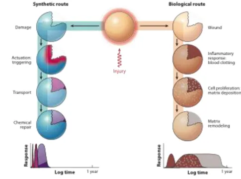
Biology provides an abundance of self-healing systems, and the healing in this case follows three principal steps:
inflammatory response (immediate),
cell proliferation (secondary),
matrix remodelling (long-term).
Synthetic systems share this three-step process, but in a more simplistic fashion and at an accelerated rate.
The main steps in this case are:
The first response is triggering (actuation), which is closely coupled to the time-scale of damage.
The second response is the transport of materials to the site of damage, again at a relatively rapid rate.
The third response, analogous to matrix remodelling, is the chemical repair process, at a time-scale that is dependent on the type of healing mechanisms employed (e.g., polymerization, entanglement, reversible cross-linking).
The healing response is dictated by the kinetic rates of all three stages depicted in Figure 1-1 actuation, transport, and repair.
- 2 -
The efficacy of healing is therefore regulated by the balance of the rate of damage versus the rate of healing. The rate of damage for a material is dictated by external factors such as the frequency of loading, strain rate, and stress amplitude. However, the rate of healing can be tailored or tuned to specific damage modes by, for example, varying the reaction kinetics through species concentration or temperature. Thus, the goal of self-healing is to achieve material stasis by balancing the rate of healing and the rate of damage.
Figure 1-1: Synthetic and biological routes to healing
1.1 Approaches to self-healing
Self-healing, as stated before, can be defined as the ability of a material to heal damages automatically and autonomously, that is, without any external intervention.
This capability can be really important because structural polymers are susceptible to damage in the form of cracks, and they can happen in places where detection is difficult and is almost impossible to repair.
- 3 -
Self-healing can be divided into two types
Autonomic self-healing : that occurs automatically without
human intervention
Non-autonomic self-healing : that needs human intervention or
an external triggering to activate the repairing mechanism. Another classification can be done according to the mechanism used to sequester the healing functionality until triggered by damage.
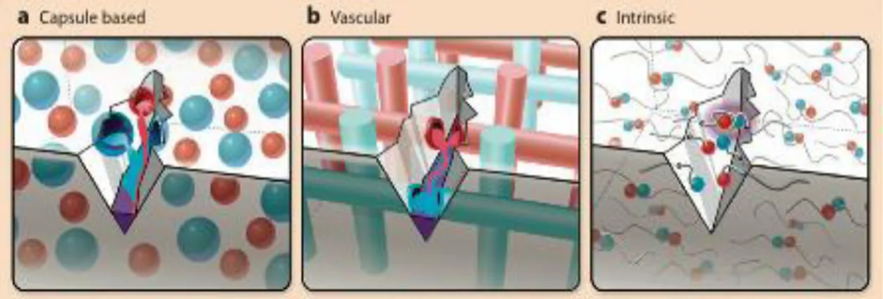
The Self-healing materials can be classified broadly into three groups:
capsule based
vascular
intrinsic
- 4 -
1.1.1 Microcapsule
It is an autonomic process as it does not need a manual or external intervention.
Embedment Microencapsulation is a process of enclosing micron-sized particles of solids, droplets of liquids, or gases in an inert shell, which in turn isolates and protects them from the external environments [2-3].
The end product of the microencapsulation process is termed as microcapsules.
It has two parts, namely, the core and the shell. They may have spherical or irregular shapes and may vary in size ranging from nano- to micro-scale.
Healing agents or catalysts containing microcapsules are used to design self-healing polymer composites.
Upon the passage of a crack through the material the microcapsules broke and the liquid adhesive flew over the fracture surface, filled the crack, and set.
The matrix provides the desired mechanical effect while the healing agent serves no purpose until after the occurrence of damage.
The required third functionality, the triggering of the healing process, is provided not by a well-defined damage sensor but by both the combined effects of fracture of the capsule wall, the catalyst in the surrounding matrix and the surface tension of the fracture surfaces, which spreads the liquid healing agent over the fracture surfaces. The problem with this solution is that it is not repeatable.
These materials were tested for space applications too [4], but they showed great problems related to the fact that they are composed materials in two different phases.
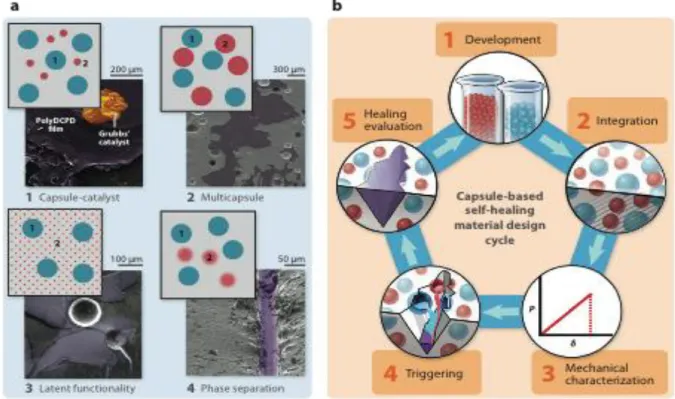
The process is presented in Figure 1-3: Capsule-based self-healing includes four main sequestration schemes. Materials with the sequestered components are labelled as 1 and 2.
1. Capsule-catalyst systems include an encapsulated healing agent and a dispersed catalyst phase.
2. Multi-capsule systems utilize two or more capsules that sequester separate components of the healing agents, an example of which is the dual-capsule PDMS system.
- 5 -
3. Latent functionality systems make use of functional groups within the matrix phase that react with an encapsulated healing agent upon damage and release, an example of which is the epoxy-solvent system.
4. Phase-separated systems include at least one healing component that is phase separated within the matrix, whereas other components may be encapsulated.
In Figure 1-3 (b) the design cycle for capsule-based self-healing materials is presented.
It is composed of :
development of encapsulation/separation technique(s)
capsule integration into the bulk material
characterization of mechanical properties
validation of damage triggering and release of healing agents
- 6 -
1.1.2 Vascular
Vascular self-healing material sequester the healing agent in a network in the form of capillaries or hollow channels, which may be interconnected until damage triggers self-healing.
The design cycle for vascular networks (Figure 1-4) can be partitioned in a manner similar to capsule-based healing systems.
Many of the same issues must be considered with regard to mechanical characterization, the triggering mechanism, and the healing performance.
Where the two systems differ is with respect to fabrication and integration within a matrix material.
Vascular self-healing is organized according to the connectivity of the vascular network. In Figure 1-4 (a) different solutions are presented:
1. One-dimensional networks are obtained from hollow channels/fibres filled with healing agent(s).
2. Two- and three-dimensional (2D and 3D) networks require more sophisticated manufacturing to ensure connectivity. The design cycle for vascular self-healing materials includes:
development of manufacturing and integration techniques
characterization of mechanical properties
validation of damage triggering and release
evaluation of healing performance
As opposed to capsule-based systems, for vascular materials the healing agents are introduced after the network has been integrated into the matrix. High viscosities and/or unfavourable wetting properties prevent efficient filling of the network, whereas chemical incompatibility endangers long-term stability of the system.
These properties also affect vascular network design, especially the channel diameter, because viscosity and wet ability affect the release and transport of the healing agent. The mechanical properties of a matrix with an embedded network are affected by the network wall
- 7 -
stiffness, the bonding between the matrix and the network, the network volume fraction, and channel distribution and uniformity. The triggering mechanisms are validated and the healing performance characterized in a manner similar to capsule-based systems. Importantly, for vascular healing systems, access to a large reservoir of healing agent and the ability to replenish the network enable repeated healing of multiple damage events.
- 8 -
1.1.3 Intrinsic
Intrinsic self-healing materials achieve repair though inherent reversibility of bonding of the matrix polymer.
Intrinsic self-healing can be accomplished through thermally reversible reactions, hydrogen bonding, ionomeric coupling, a dispersed meltable thermoplastic phase, or molecular diffusion. Intrinsic self-healing materials have been demonstrated using three main schemes:
1. Reversible bonding schemes make use of the reversible nature of certain chemical reactions that have been adapted to self-healing applications.
2. Chain entanglement approaches utilize mobility at crack faces to entangle chains that span the crack surfaces.
3. Non-covalent self-healing systems rely on reversible hydrogen bonding or ionic clustering that manifests as reversible cross-links in polymers, an example of which is the poly(ethylene- co-methacrylic acid) (EMAA) self-healing ionomer.
The design cycle of intrinsic materials is composed of : matrix material development
mechanical characterization of the material
validation of triggering
evaluation of healing performance, typically with the intervention of external energy.
- 9 -
Figure 1-5 : Intrinsic self-healing material and material design cycling
The design cycle of intrinsic self-healing materials is less complex than that of capsule-based and vascular self-healing materials.
For intrinsic systems, the matrix is inherently self-healing, and sequestration of healing agents is no longer required, avoiding many of the problems with integration and healing-agent compatibility that arise in vascular and capsule-based self-healing materials.
However, intrinsic self-healing materials must also meet the desired mechanical, chemical, and optical properties for intended applications.
In this thesis the interest is focused on Ionomeric self-healing materials.
- 10 -
1.2 Ionomers
Inspired by the nature, researchers have designed and developed various materials with self-healing property, among which, polymeric materials are by far the most studied probably due to their ease to functionalize and modify [5].
In 1965, Rees and Vaughan defined ionomers as olefin-based polymers containing a relatively small percentage of ionic groups in which “strong ionic inter-chain forces play the dominant role in controlling properties”.[6]
A new definition by Eisenburg and Rinaudo in 1990 stated that ionomers are “polymers in which the bulk properties are governed by ionic interactions in discrete regions of the material (ionic aggregates)”.
Summing up, it’s possible to define ionomers as a class of polymers which have up to 20 mol% of ionic species incorporated into the structure of the organic polymer.
These ionic species create interactions or aggregates, not present in comparable non-ionic polymers that have a profound effect upon the mechanical and physical properties of the polymer.
Really interesting is the self healing phenomenon exhibited by ionomers thanks to their unique chemical structure.
1.2.1 Molecular structure
As previously said the self healing mechanism of ionomers is unlike other self healing mechanisms, as it is controlled by the inherent chemical structure and morphology of the polymer.
The benefit of this, in contrast to other self healing processes where a “healing agent” is added, is that the process is potentially repeatable many times, being dependent only upon subsequent polymer degradation.
In addition, this mechanism is not an autonomic process but must be “activated” through the sufficient transfer of high thermal energy forces, as the impact of a bullet, for example [7].
In fact during impact, the transfer of energy from the bullet first rapidly heats up the impacted polymer.
- 11 -
The presence of ionic species creates ionic domains or “aggregates”, which have been generally interpreted as consisting of several ion pairs known as multiplets.
The size and number of ion pairs in any given multiplet will be governed by steric factors, flexibility of the polymer chain, the size of the ion pairs and the dielectric constant of the polymer backbone. These multiplet also create regions of restricted mobility which effectively form a “physical crosslink”.
Figure 1-6 :A multiplet and a region of restricted mobility
As the ion content or strength increases, separate phase transition behaviour can be observed with new morphologies and structures which can dominate the structure and so the properties of the ionomer.
The potential reversible nature of these physical cross-links is a critical factor in the ability to self heal.
Another critical aspect is the understanding of the morphological changes which occur during heating.
The order-to-disorder transition model of ionic clusters was proposed by Tadano et al. [6] to explain the changes observed during thermal expansion and calorimetric studies.
As shown in Figure 1-7, the model consists of three different phases controlled by temperature.
- 12 -
Figure 1-7 : Phase transition diagram
The first phase consists of ordered ionic clusters, polyethylene crystallites and an amorphous region. When the temperature is increased to above the order-to-disorder transition temperature (Tdis),
the order within the ionic aggregates is lost along with the strength of the physical cross-links.
As the temperature is further increased, the polymer crystallites melt (Tm) even though the disordered aggregates persist in the
molten state.
Conversely, when the temperature is cooled from above the melting point, re-crystallisation takes place rapidly while the reordering of the ionic cluster occurs more slowly through a relaxation process. Again, the transformations which occur here are critical to the self healing process.
After ballistic penetration, when the thermal energy of impact dissipates, this model suggests that healing can occur through a two-step process:
solidification or re-crystallisation
- 13 -
Another fundamental process that facilitates self healing in ionomer systems is the concept known as ion hopping [8].
Ionic aggregates persist in the melt up to 300 °C and greatly increases the melt strength or viscosity compared to the parent non-ionic polymer.
Figure 1-8: Ion hopping
Ion hopping is used to indicate when the ionic species within a given polymer are observed to “hop” from one aggregate to another.
Ionic associations are dynamic, in that they have a finite lifetime, which is a measure of the average length of time an ionic group spends in a particular aggregate.
The ions “hop” from one aggregate to another allowing the relaxation of the chain segment of the macromolecule to which the ionic group is attached.
With this mechanism occurring at random time intervals, the entire polymer can diffuse and flow without requiring all of the ionic associations to be released simultaneously.
In relation to the self healing process, this provides the physical mechanism to allow the polymer structure to exhibit elastomeric behaviour in the melt while also maintaining an adequate level of processability.
- 14 -
1.3 Multilayers and selfhealing materials for space
applications
Multi-layers are highly used in space exploration, they are used in different situations and as solutions for different problems.
Some of this solutions are presented below.
launches have really high costs, and this provides ample incentive to seek innovative, cost-effective ways to reduce structural mass without sacrificing safety and reliability. Damage-tolerant structural systems can provide a route to avoiding weight penalty while enhancing vehicle safety and reliability. Self-healing polymers capable of spontaneous puncture repair show great promise to mitigate potentially catastrophic damage from events such as micro-meteoroid penetration. Effective self-repair requires these materials to heal instantaneously following projectile penetration while retaining structural integrity. The problem is that self-healing materials, such as Surlyn® are usually not suitable for
structural functions, that’s why multilayers are used. The main strategy is to incorporate secondary functional materials capable of counteracting service degradation whilst still
achieving the primary, usually structural, requirement.
Inflatable and deployable flexible-walled structures have been used in numerous space missions since the dawn of space exploration. Some examples include communications satellites (ECHO, Explorer), missile decoys, space suits, airlocks
(Voskhod 2), and impact attenuation airbags (Luna, Pathfinder, MER). The benefits of using structures with readily collapsible walls realized in several system metrics of critical importance. The first is stowage volume (or packing efficiency), which can have a profound effect on launch vehicle size and thus mission cost. This benefit is compounded by the ability to pack flexible materials in irregular spaces to take advantage of all available launch volume. The second important advantage of inflatable structures is the mass
- 15 -
advantage that is realized when comparing all features equally with mechanical systems. Inflatable systems also have very few mechanical components and are therefore of lower complexity, and thus higher reliability compared to
mechanically deployable systems. These inflatable structures, such as space suites also typically have multiple layers that include a bladder, restraint, and Thermal Protective Layer (TPL), Figure 1-9 shows typical ply-ups.
Figure 1-9 : Space suit and inflatable structure ply-ups
The function of the bladder layer is to contain inflation gas. The bladder is typically a film or a coated/laminated structure. The restraint layer is a high strength fabric or webbing system used for structural support and shape control. The TPL is a multi-layer, multi-functioning structure. In the space suit, multiple layers of aluminized Mylar™ serve to provide thermal protection. Fabrics that provide hyper-velocity protection and abrasion resistance, and spacer materials are used in
conjunction with the Mylar™ to provide MMOD protection in the form of a Whipple bumper. A risk for inflatable structures, both flexible and non-flexible (metal), is puncture and leakage. External threats include hyper-velocity micro-meteoroid
- 16 -
tools or equipment. Internal threats include abrasion and penetration from accidental crew impact. [9]
Multi-layers are used as thermal protection too, the MLI is composed by thin sheets of different materials and is used for thermal insulation of spacecrafts.
In intrinsically selfhealing materals, as ionomers and ENR50, the response to mending capability is related to the impact energy, which should be sufficient to activate healing. As a matter of facts, impacts in space generally occur at hypervelocity, but in previous works [16,17,26] it was proven that low speed impacts are usually more critical for material healing. Moreover, possible interactions between different layers may affect the healing response. For these reasons, in this thesis, the impact behavior of Sulryn/ENR50 multilayers is investigated by low speed testing with the lab facilities (LAST) available at Politecnico. Further investigation by high speed testing will be performed in a next study.
- 17 -
2 Materials and their characteristics
In the following chapters, the materials used in the production of multilayer are introduced and their characteristics presented.
Rheological tests were performed in order to study the viscosity of the materials and then an ad-hoc productive process has been studied to produce the samples for the ballistic tests.
2.1 Surlyn®
Surlyn® is an ionomer synthesized by DuPont.
Surlyn® is the random copolymer poly(ethylene-co-methacrylic acid), with 5.4 mol % methacrylic acid (MA), which has been neutralized with a cation as can be seen in Figure 2-1.
Figure 2-1: Surlyn® 8940
Surlyn® 8940 has 30% of the 5.4 mol % MA groups neutralized with sodium and Surlyn® 8920 has 60% of the 5.4 mol % MA groups neutralized with sodium.
Both have excellent clarity, stiffness, and chemical resistance and viscosity will be investigated in the following chapters.
Surlyn® 8940 is known for its cut resistance and toughness and is used, for example, in ski boots and ice skate shells.
Surlyn® 8920 is lightweight, has good flex response at low temperature, great toughness, and high impact resistance. It is used in applications such as ski laminating films.
- 18 -
2.1.1 Surlyn® 8940 properties
The typical properties of Surlyn® 8940 are reported in the table below.
Physical
Density 0.95 g/cm3
Melt flow rate (190 °C/ 2.16kg) 2.8 g/ 10 min Thermal
Melting point 94 °C
Freezing point 59°C
Vicat softening point 63 °C
Table 2-1 : Properties of Surlyn® 8940
2.1.2 Surlyn® 8920 properties
The typical properties of Surlyn® 8920 are reported in the table below.
Physical
Density 0.95 g/cm3
Melt flow rate (190 °C/ 2.16kg) 0.9 g/ 10 min Thermal
Melting point 88 °C
Freezing point 48°C
Vicat softening point 58 °C
- 19 -
2.2 Nucrel® 960
Nucrel® 960 is a copolymer of ethylene and methacrylic acid, made with nominally 15 wt% methacrylic acid. It is inherently flexible without the need for plasticizers. The resin can be pigmented, UV-stabilized for exterior applications and painted or plated for special decorative effects.
2.2.1 Properties
The typical properties of Nucrel® 960 are reported in the table below.
Physical
Density 0.94 g/cm3
Melt flow rate (190 °C/ 2.16kg) 60 g/ 10 min Thermal
Melting point 91 °C
Freezing point 73 °C
Vicat softening point 62 °C
Table 2-3 : Properties of Nucrel® 960
2.3 ENR 50
Epoxidized natural rubber (ENR) is a modified natural rubber (NR). A typical formation of ENR from NR, cis-1,4-isoprene, employing peracetic acid is shown in Figure 2-2[10-11].
The isoprene (C) and epoxidized isoprene (E) act as monomer units that are randomly distributed along the polymer chain. Various degrees of epoxidation of NR are available. For examples, the
isoprene units in the polymer chain are 25%, 50% and 75% epoxidized in ENR-25, ENR-50 and ENR-75, respectively.
- 20 -
Figure 2-2 Modification of NR to ENR
2.4 Production of samples
2.4.1 Surlyn® and Nucrel®
For each material a compression moulding technique has been used to get the samples.
The Surlyn® is supplied in pellets.
In order to have a sufficiently dry material, the pellets were put in the oven at 60 °C for 2 hours.
For the characterization tests and the ballistic test, many samples were produced.
The production of the samples follows some principal steps:
the mould is heated up to 180 °C, as it is the most suitable temperature to have a good compression moulding [12]
the pellets are weighed in order to obtain the desired thickness, this is possible because the density of the material is known
a Teflon® plate is put in the mould in order to prevent the Surlyn® from sticking to the mould.
the pellets are distributed on the Teflon® plate, and covered with a second Teflon® plate
- 21 -
the temperature is immediately brought to 30 °C and the sample is pulled out from the mould.
The samples are 120x120 mm and with variable width. 2.4.2 ENR 50
This material is given in blocks.
It flows with great difficulty due to the high mol wt and viscosity, even at high molding temperature.
The production of the samples follows some principal steps:
the mould is heated up to 180 °C
the material is weighted in order to obtain the desired thickness, this is possible because the density of the material is known
a Teflon® plate is put in the mould in order to prevent the ENR50 from sticking to the mould.
the material is cut in small pieces, like pellets, to help the production
the pellets are distributed on a Teflon® plate, and covered with a second Teflon® plate
a high pressure is applied to the mould and counter-mould.
the temperature and the pressure are kept constant for 45 minute
then the temperature is brought to 30 °C and the sample is pulled out from the mould.
The samples are 120x120 mm and with variable width.
In this case it is more difficult to control the width as ENR50 is more complicated than the Surlyn® to deal with.
- 22 -
2.4.3 Multilayers
For this thesis, multilayers composed of Surlyn® 8940 and ENR50 with 3 5 and 7 layers were produced.
For all of them the same procedure is used, but before finding the right way to proceed, many attempts were made.
1. The vacuum bag: the different layers were superimposed
and put inside the vacuum bag then it was put in the oven at 80 °C, in order to have the Surlyn® softened but not melting.
The vacuum bag was kept at the same temperature for 1 hour.
In this way, the different layers did not stick completely and there were air bubbles between the layers.
Even if the vacuum bag was used, the presence of ENR50 would prevent the air from going outside.
2. The vacuum bag: putting a weight on it in order to apply a
very light pressure. The result was the same as the previous try.
From the two first attempts, it is clear that only the heat is not sufficient to stick together the different layers, so the third try was made using the press.
3. The different layers were superimposed and put in the press mould, the first and last layer were covered by two Teflon® plates.
The mould and counter-mould were heated at 80 °and then a light pressure was applied.
The pressure must be enough to make the air bubble come out from the layers but can’t be too high in order to not lose the upper Surlyn® layer. The press was kept at the same temperature for 1 hour.
The multilayer produced with the last technique was perfect, with only some impurity on the borders, the first Surlyn® layer on the top was thinner than the others.
- 23 -
In order to reduce the production time the last attempt was made:
4. the procedure was kept equal to number 3, but the 1 hour time at temperature was reduced to half an hour, but the result was not satisfactory because the layers were not sufficiently stuck together.
Finally the principal steps to follow for the production of the samples are:
the mould is heated up to 80 °C, in order to not have the Surlyn® totally melted
a Teflon® plate is put in the mould in order to prevent the Surlyn® from sticking to the mould
the layers are superimposed to form the multilayer
a Teflon® plate is put on the top of the multilayer to prevent the Surlyn® from sticking to the counter-mould
a light pressure is apply to the mould and counter mould
the temperature and the pressure are kept constant for 1 hour
then the temperature is brought to 30 °C and the sample is pulled out from the mould
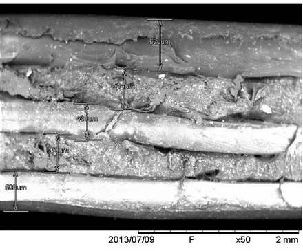
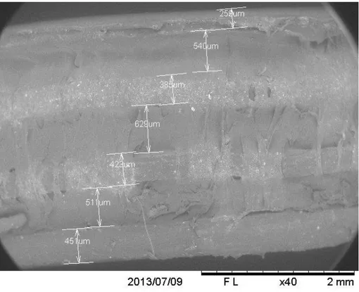
Below, the pictures of the multilayer taken with the scanning electron microscope (SEM) are presented.
This method for the rubber is not precise, as previously stated, in fact is possible to notice that the thickness of the rubber layers are different even if they were made following the same procedure.
In addition it is possible to notice that in the 7 layers the upper Surlyn® layer is smaller, that’s because while pressing the multilayer to compact it, the upper layer, partially molten, flows out of the mould.
Another remark that is possible to do looking at the figures is that the layers are not always perfectly stuck together.
That is probably related to the particular behavior of the rubber and to the pressing procedure which may be further optimized.
- 24 -
Figure 2-3 : 3 layers Multilayer
- 25 -
- 26 -
2.5 Performed test
2.5.1 Rheometer
Rheology can be defined as the science of the flow and deformation of materials.
For many simple fluids, the study of rheology involves the
measurement of viscosity. However, the rheology of polymers is much more complex because polymeric fluids show non ideal behaviour. A rheometer is the instrument used to investigate flow deformation properties of materials via dynamic or steady shear measurements. These measurements are commonly made in parallel plate or cone and plate fixtures.
In this thesis the parallel plate solution is used.
In dynamic oscillation test, shear stresses are applied by sinusoidal oscillation and a phase angle is measured as a function of time and temperature.
The ratio of the stress amplitude to strain as a function of time and temperature determine the shear modulus (G).
The shear storage modulus (G’) represents the elastic behaviour and the shear loss modulus (G”) represents the viscous behaviour.
Steady shear measurements are unique to the rheometer and are used to measure the flow properties of a material, such as viscosity. When measuring viscosity, a stress is applied to the sample and the rate of strain is measured, or vice versa.
Commonly polymeric materials exhibit non-newtonian, pseudoplastic behaviour.
- 27 -
Figure 2-6 : Parallel plate rehometer
In the following chapters the results of dynamic and static tests are presented. The tests were performed on all the materials (except the static test on the ENR50), even if the multilayers are made only by Surlyn® 8940 and ENR50.
That’s because the data could be useful for other studies.
In this thesis, the decision to concentrate the ballistic test only on Surlyn® 8940 was driven by previous works [13 14].
In fact the Surlyn® 8940 is the one that shows the best self-healing behaviour in the pure case for low velocity impact.
2.5.1.1 Dynamic test
The rheological measurements were performed on a controlled stress melt rheometer. Polymer pellets were melted, compressed and
stamped into discs with a diameter of 25 mm and a thickness of 1 mm. Parallel plates were used.
Oscillatory measurements were performed at different temperatures with a frequency sweep between 50 and 0.5 Hz.
When a material undergoes oscillatory stress, the response can be expressed in terms of a storage modulus, G’ (G prime) a loss modulus, G’’ (G double prime) and a complex viscosity, η* (Eta star).
The graphs of the results of the different tests with the different materials are presented below.
- 28 -
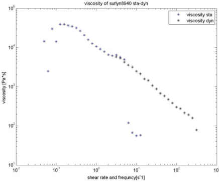
Figure 2-7 : Complex viscosity of Surlyn® 8940
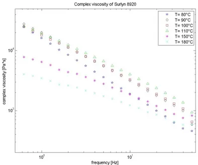
Figure 2-8 : Complex viscosity of Surlyn® 8920
- 29 -
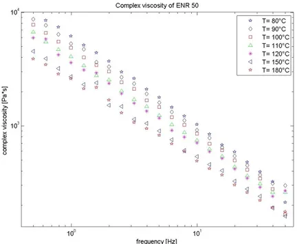
Figure 2-9 : Complex viscosity of Nucrel® 960
- 30 -
From Figure 2-7 and Figure 2-8, it is possible to see that around the temperature of 180 °C, the viscosity of the material is sufficiently low to permit a good but not excessive fluidity and, as a consequence, a good moulding.
The same can be seen for the Nucrel® 960.
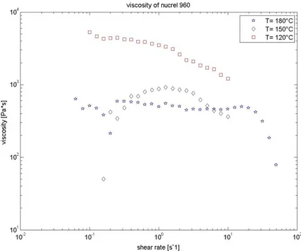
But from Figure 2-10 it is possible to see that the viscosity of the ENR50 is at 180 °C is consistently higher than Surlyn and doesn't change much while changing the temperature.
The high elastic return and the diffficulty in softening even at high temperature make ENR50 very difficult to mold into flat layers. Cutting of the rubber in small pellets allowed to partially solve the molding problems.
2.5.1.2 Static test
The rheological measurements were performed on a controlled stress melt rheometer. Polymer pellets were melted, compressed and
stamped into discs with a diameter of 25 mm and a thickness of 1 mm.
Parallel plates were used.
Steady state measurements were performed at different
temperatures (180 °C 150 °C and 120 °C) with a shear rate of 0,01 s-1.
- 31 -
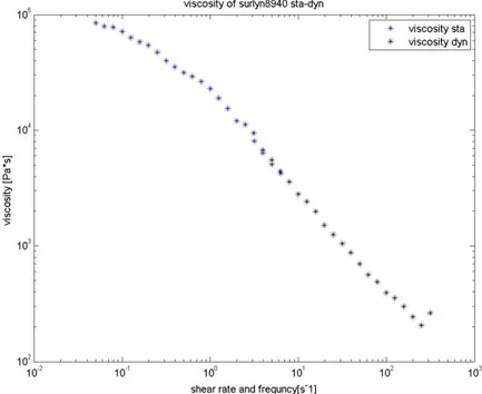
Figure 2-11 : Viscosity vs shear rate of Surlyn® 8940
- 32 -
Figure 2-13 : Viscosity vs shear rate of Surlyn® 8920
As it is possible to see from the figures above, at 120 °C the material has a high viscosity and so the test was stopped before the end because the value of the applied torque was too high.
- 33 -
2.5.1.3 Cox-Merz rule
The so-called Cox-Merz "rule", is an empirical relationship which has been found to be of great use in rheology.
It was observed by Cox and Merz [15] that for many polymeric systems correspondence occurred between the steady state shear viscosity, plotted against shear rate, and the magnitude of the complex viscosity, plotted against angular frequency.
It is important in the application of the rule to ensure that the appropriate values for η and η’ are used.
For example, in both cases, it is the steady state values which are required, i.e. any transient effects due to flow or oscillation start-up, inertia must have fully decayed.
If applied correctly, the Cox-Merz rule can be of great value in polymer rheology, and there are several circumstances in which it might be used.
1. The principle use is probably to predict the steady state viscosity from oscillatory measurements. For many polymeric systems the steady state viscosity is difficult to measure at high shear rates, because of sample fracture, secondary flows and so forth. Data obtained from oscillatory experiments are usually more reliable.
The characteristic shear rate for the ballistic testing
performed here is estimated to be on the order of 10^3 1/s (ỳ =
v/d = 18000/0.8), based on a projectile velocity of 180 m/s and a projectile diameter 0,8 cm.
It is quite high and as shown in previous graphs, the state viscosity is not possible to be obtained with the static test. [16] 2. The rule can also be used to predict η* from steady state
viscosity data, for example in circumstances in which the oscillatory operating mode is not available.
3. The rule can also be used in an analytical sense. A good deal can be learned about the micro-structure of materials from the degree to which they adhere to the rule.
- 34 -
The applicability of the Cox-Merz rule has been reviewed in detail [17]. It has been found to hold for almost all polymer melts, and concentrated and semi dilute solutions.
Deviations from the rule occur at high frequencies, and the oscillatory data can either over or under estimate the steady state data.
The graphs are at temperatures from 120 °C to 180 °C.
Figure 2-14 : Cox –Merz rule Surlyn® 8940 at 120 °C
- 35 -
Figure 2-15 : Cox –Merz rule Surlyn® 8940 at 150 °C
- 36 -
Figure 2-17 : Cox –Merz rule Surlyn® 8920 at 120 °C
- 37 -
Figure 2-19 : Cox –Merz rule Surlyn® 8920 at 180 °C
- 38 -
Figure 2-21 : Cox –Merz rule Nucrel® 960 at 150 °C
- 39 -
In the past, it could confidently be stated that no theoretical basis for the Cox-Merz rule had yet been provided, and indeed some workers felt that the correspondence was merely fortuitous.
However, several, admittedly partial, justifications have been offered [18,19].
A starting point is a requirement of continuum mechanics that the dynamic viscosity and the steady state viscosity are related in the low frequency and shear rate limits, i.e
η’ω→0 = η(ỳ)ỳ→0 (1)
where η’= G’’(ω)/ω.
In the limit the two experimental modes are effectively identical. This equality can be used as a check on the reliability of oscillatory and steady state data. The elastic contribution to η’(ω) disappears in the low frequency limit, and Equation can be rewritten as:
η*ω→0 = η(ỳ)ỳ→0
- 41 -
3 Ballistic tests
The low speed impact studies were used to probe the healing process of the ENR50-Surlyn® 8940 multilayers.
The tests were performed in the LAST laboratory of the Politecnico di Milano.
The goal of these tests is to gain insight on the healing mechanism and to compare the results with the ones of the pure Surlyn® 8940. [20, 13]
Puncture healing in these materials is dependent on how the
combination of the polymer’s viscoelastic properties responds to the energy input from the puncture event which results in an increase of temperature in the vicinity of the impact.
Self-healing behavior occurs upon projectile puncture whereby energy is transferred to the material during impact both elastically and inelastically thus establishing two requirements for puncture healing to occur:
The need for the puncture event to produce a local melt state in the polymer material
The molten material has to have sufficient melt elasticity to snap back and close the hole
In order to have healing it’s necessary that the material melts and has a sufficient elastic return, without these two conditions the healing can’t take place [21].
- 42 -
3.1 Description of the test equipment
The test equipment is composed of an air gun and a target used to keep the sample in front of the barrel (at a distance of 200 mm). The bullets are round balls of steel of different radius, as they are really small in comparison to the diameter of the barrel, in order to shoot it correctly, a sabot is used to accelerate the bullet in the barrel. The sabot is made of polyethylene and the technical design is
presented in Figure 3-6, the balls are inserted in the hole at the top of the sabot and fixed to it with adhesive tape, in order to avoid the exit of the ball before the shoot.
- 43 -
The gun is composed of:
a tank, which is able to maintain a pressure of 7 bar.
a barrel of 6 m with an external diameter of 70 mm and an internal diameter of 40 mm.
an aluminum stopper to stop the sabot from leaving the barrel together with the bullet
The barrel and the tank are clamped together by bolts and the tightness is assured by a rubber gasket.
The stopper was composed of a principal body that can be used at each shot and an aluminum tube of 120 mm long that has the task of absorbing the impact energy of the sabot by plastically deforming. But in order to have less problems related to the excessive
deformation of the tube, the stopper was re-designed adding a steel part to have less deformation.
- 44 - Figure 3-3 : Stopper
A critic aspect of the system is the valve used to keep the pressure in the tank.
It is made of a gold bronze laminate put in front of the tank and screwed up in the connection tunnel.
A non-precise placement of the laminate or a premature rupture of it would result in a failure.
- 45 -
The target is at 200 mm from the stopper of the gun, and is fixed with bolts to a rigid structure fixed to the ground.
When needed, in order to avoid the bouncing of the bullets on the rigid structure, a frame of Styrofoam of 50 mm of thickness can be used, as shown in Figure 3-5.
The data acquisition system is really important in this kind of test. In impact tests, the bullet speed is a really important data to have, and so a high speed camera was used.
The camera was put above the target, as shown in Figure 3-7.
Knowing the number of frames per second (21017 fps), it’s possible to compute the time interval between each frame and, as a consequence, the speed of the bullet.
Figure 3-5 : The target
- 46 -
Figure 3-6 : The sabot
.
- 47 -
3.2 Tests and results
For the tests, steel spheres of different mass and diameter were used, in the table below the characteristics of the projectile are presented.
Mass [g] Diameter [mm] 0.053 2.35 0.110 3 0.41 4 0.511 5 0.62 5.5 1.041 6.35 2.091 8 4.084 10 7.057 12
Table 3-1 : Projectile characteristics
The variables that is possible to modify during the impact test are: speed of the projectile
thickness of the sample
number of layer
diameter of the projectile.
In this case the speed of the projectile is kept fixed.
In fact the maximum nominal velocity that can be reached is 200 m/s which is the one related to the pressure of 6 bar in the reservoir. But in order to be able to compare the results with the ones presented in the previous publications [20] the speed was kept constant and around 180 m/s.
- 48 -
In addition, the thickness of the layers was kept constant too, as the ENR50 samples were difficult to produce, and the thickness of 0.4 mm was the best compromise.
So the only two variables that were kept in account, were the number of layers (and so the total thickness of the sample) and the diameter of the projectile.
The aim of the test is to estimate the limiting ratio thickness/diameter for which the healing process works. 3.2.1 ENR 50
The objective of this thesis is to evaluate the healing efficiency of multilayers of Surlyn® 8940 and ENR50.
But before analyzing the multylayers, a test on the EN50 was made too, in order to confirm, what said in previous studies [22], that ENR50 has self-healing properties.
A square sample (120 X 120 mm) of ENR 50 was mounted on the target and the impact test was performed.
In this case only two tests were made: the first shot was made with a
projectile with diameter of 8 mm and the ENR50 showed a good self-healing response.
The same happened with the projectile of diameter 12 mm. The tests results are reported in Table 3-2.
From Figure 3-8 and Figure 3-9:, it is possible to notice that after the impact, even if it is possible to recognize the impact zone, there is no hole.
ID Diam [mm] Mass [g] Thickness [mm] [m/s] Vin Vout [m/s] [m/s] ∆V Egiven [J] s/d
Self healing Effect
1 8 2.092 1 180 105 75 5.9 0.125
2 12 7.06 1 190 120 70 17.3 0.08
- 49 -
- 50 -
Figure 3-10 : Reaction of ENR50 during the shot
In Figure 3-10it is possible to notice the great deformation that the ENR50 encounters during the test.
It is really higher than the one of the Surlyn® 8940 and there is no melting, since ENR is a non-crystalline rubber.
The self healing mechanism of the ENR50 is different from the one of the Surlyn® 8940 where viscoelasticity as well as recrystallization are responsible for the healing process.
- 51 -
Figure 3-11 : Energy comparison : ENR50 vs Surlyn® 8940
In addition from Figure 3-11it’s possible to notice that the ENR50 dissipate much more energy than the pure Surlyn® 8940.
This can be explained considering the high deformation of the rubber before failure.
This can be seen even taking into account the difference between the two different projectiles used: for the 12 mm diameter ball the
dissipated energy is more than for the 8 mm diameter ball, that happened because the projectile is heavier and the surface exposed to friction is bigger.
- 52 -
3.2.2 Multilayer: 3 layers
The first tests were made on 3 layers multilayer. The sample is made as in Figure 3-12.
Figure 3-12 : 3 Layers sample
In Table 3-3 the results of the tests are presented.
ID Diam [mm] Mass [g] Thickness [mm] Vin
[m/s] [m/s] Vout [m/s] ∆V Egiven [J] s/d bouncing
Self healing Effect 3 3 0.110 1.4 175 0 175 1.68 0.47 4 4 0.41 1.4 161 0 161 5.36 0.35 5 5 0.511 1.4 175 0 175 7.8 0.28 6 5.5 0.62 1.4 175 75 100 3.1 0.25 7 6.35 1.041 1.4 150 62 88 4.03 0.22 8 8 2.091 1.4 175 131 44 2 0.17 9 3 0.110 1 175 95 80 0.35 0.3 10 5 0.511 1 175 55 120 3.7 0.2
Table 3-3 : 3 layers sample ballistic test
Considering the results of the tests and comparing them with the ones presented in previous thesis [13] it is possible to see that the presence of the ENR50 in the multilayers brings some differences. First of all samples of pure Surlyn® with a thickness of 1.4 mm were perforated by projectiles of diameter 2 and 3 mm and they showed self healing effect, this is not true for multilayers.
- 53 -
In fact the multilayer prevents the penetration of the projectile until the diameter is of 5.5 mm.
But on a lower thickness (1 mm) the presence of a multilayer is of no utility, in fact the multilayer works in the same way of a sample of Surlyn® 8940 of the same thickness.
In Figure 3-13 is possible to notice that even if the two solutions are working in the same way, the mechanism during the impact is quite different.
In fact in the case of pure Surlyn® , the dissipated energy during the impact is lower than the one of the multilayer, so the presence of the ENR50 increases the dissipated energy.
Considering the fact that there is a high difference of the ∆E in the case of the 3 mm and 5 mm projectile, it is possible to assume that the presence of ENR50 increases the absorbed energy due to a markedly higher deformation of material before puncture and possibly to an increase of friction.