DiSIT, Computer Science Institute
Universit`a del Piemonte Orientale “A. Avogadro” Viale Teresa Michel 11, 15121 Alessandria
http://www.di.unipmn.it
UML class diagrams supporting formalism definition in the Draw-Net Modeling System
D. Codetta Raiteri ([email protected]) TECHNICAL REPORT TR-INF-2019-07-04-UNIPMN
Research Technical Reports published by DiSIT, Computer Science Institute, Universit`a del Piemonte Orientale are available via WWW at URL http://www.di.unipmn.it/.
Plain-text abstracts organized by year are available in the directory
Recent Titles from the TR-INF-UNIPMN Technical Report Series
2019-03 Tracing and preventing sharing and mutation, P. Giannini, M. Servetto, E. Zucca, July 2019.
2019-02 The Android Forensics Automator (AnForA): a tool for the Automated Forensic Analysis of Android Applications, C. Anglano, M. Canonico, M. Guazzone, June 2019.
2019-01 Deriving Symbolic and Parametric Structural Relations in Symmetric Nets: Focus on Composition Operator, L. Capra, M. De Pierro, G. Franceschinis, March 2019. 2018-03 Deriving Symbolic Ordinary Differential Equations from Stochastic Symmetric Nets
without Unfolding, M. Beccuti, L. Capra, M. De Pierro, G. Franceschinis, S. Per-nice, July 2018.
2018-02 Power (set) Description Logic, L. Giordano, A. Policriti, February 2018.
2018-01 A Game-Theoretic Approach to Coalition Formation in Fog Provider Federations (Extended Version), C. Anglano, M. Canonico, P. Castagno, M. Guazzone, M. Sereno, February 2018.
2017-02 Configuration and Use of Android Virtual Devices for the Forensic Analysis of An-droid Applications (see below for citation details), C. Anglano, M. Canonico, M. Guazzone, June 2017.
2017-01 A dynamic simulation model for comparing kidney exchange policies, M. Beccuti, G. Franceschinis, S. Villa, March 2017.
2016-04 Tracing sharing in an imperative pure calculus, P. Giannini, M. Servetto, E. Zucca, December 2016.
2016-03 SUPPORTING DATA COMMUNICATION AND PATIENT ASSESSMENT DUR-ING EMERGENCY TRANSPORTATION, M. Canonico, S. Montani, M. Striani, September 2016.
2016-02 TECHNICAL NOTE TO Forensic Analysis of the ChatSecure Instant Messaging Application on Android Smartphones (see below for citation details), C. Anglano, M. Canonico, M. Guazzone, September 2016.
2016-01 Reasoning in a rational extension of SROEL, L. Giordano, D. Theseider Dupr´e, May 2016.
2014-02 A Provenly Correct Compilation of Functional Languages into Scripting Lan-guages, P. Giannini, A. Shaqiri, December 2014.
2014-01 An Intelligent Swarm of Markovian Agents, A. Bobbio, D. Bruneo, D. Cerotti, M. Gribaudo, M. Scarpa, June 2014.
2013-01 Minimum pattern length for short spaced seeds based on linear rulers (revised), L. Egidi, G. Manzini, July 2013.
2012-04 An intensional approach for periodic data in relational databases, A. Bottrighi, A. Sattar, B. Stantic, P. Terenziani, December 2012.
Contents
1 Introduction 2
2 DMS general architecture 3
2.1 The formalism level . . . 3 2.2 The model level . . . 4 2.3 The solver level . . . 4
3 CD based management of formalisms 4
3.1 Types of classes in the CD . . . 5 3.2 Building the system model . . . 9
4 Conclusions and future work 9
Acknowledgements 11
UML class diagrams supporting formalism definition in
the Draw-Net Modeling System
Daniele Codetta-Raiteri
DiSIT, Istituto di Informatica, Università del Piemonte Orientale
Viale Teresa Michel 11, 15121 Alessandria, Italy
e-mail:
[email protected]
Abstract
The Draw-Net Modeling System (DMS) is a customizable framework supporting the design and the solution of models expressed in any graph-based formalism, thanks to an open architec-ture. During the years, many formalisms (Petri Nets, Bayesian Networks, Fault Trees, etc.) have been included in DMS. A formalism defines all the primitives that can be used in a model (nodes, arcs, properties, etc.) and is stored into XML files. The paper describes a new way to manage formalisms: the user can create a new formalism by drawing a UML Class Diagrams (CD); then the corresponding XML files are automatically generated. If instead the user intends to edit an existing formalism, a “reverse engineering” function generates the CD from the XML files. The CD can be handled inside DMS, and acts an intuitive and graphical “meta-model” to represent the formalism. An application example is presented.
Keywords: Draw-Net, formalisms, models, UML, Class Diagram, XML, meta-model, Petri Net. Acronym list:
CD Class Diagram
DMS Draw-Net Modeling System MDE Model Driven Engineering PN Petri Net
UML Unified Modeling Language XML eXtensible Markup Language
1
Introduction
The design of complex systems can be fruitfully supported by modeling: both qualitative and quan-titative measures can be evaluated on the models, and the results can be used to guide the design. Models are the basis of Model Driven Engineering (MDE) techniques [1], and it is very important to pursue the goal of embedding in a single flexible framework the possibility of choosing among multiple modeling formalisms and solution methods, in order to represent and evaluate the system by means of the most suitable model and solver. Software tools for performance and dependability analysis have been developed with this goal in mind, such as Möbius [2] and SHARPE [3], but the set of supported formalisms is usually predefined and closed.
The Draw-Net Modeling System (DMS) [4, 5] is a customizable framework supporting the design and the solution of models expressed in any graph-based formalism. The system is characterized by
an open architecture and includes an XML based language family that can be used to define existing as well as new formalisms and the models expressed through such formalisms. The original idea behind DMS, that differentiates it from the other approaches, is the possibility of easily adding new formalisms and the fact that it favours the reuse and integration of existing tools for solving models. The addition of new formalisms does not need to recompile the source code of DMS, and solvers can be integrated with a little programming effort.
During the years, many formalisms (Petri Nets [6, 7, 8], Bayesian Networks [9, 10, 11], Fault Trees[12, 13, 14], etc.) and the corresponding solvers have been included in DMS. The formalisms can be created or edited by manually manipulating the corresponding XML files which have a quite complex structure. So, the Draw-Net Formalism Generator (DNForGe) was implemented inside DMS, and is the graphical editor allowing the user to create or modify all the formalism primitives in a more intuitive way (Sec. 2).
This paper describes a third way to manage formalisms, which has been recently implemented and exploits UML [15] and Class Diagrams (CD) in particular: by means of Draw-Net (the model editor of DMS), the user can create a new formalism by drawing a CD model where several types of class represent the primitives of the formalism (nodes, arcs, properties, constraints, solvers); then, the corresponding XML files are automatically generated, and can be used to build models according to the formalism, still by means of Draw-Net. If instead the user intends to edit an existing formalism, a “reverse engineering” function generates the CD from the XML files (Sec. 3).
Sec. 4 concludes the report with possible future work.
2
DMS general architecture
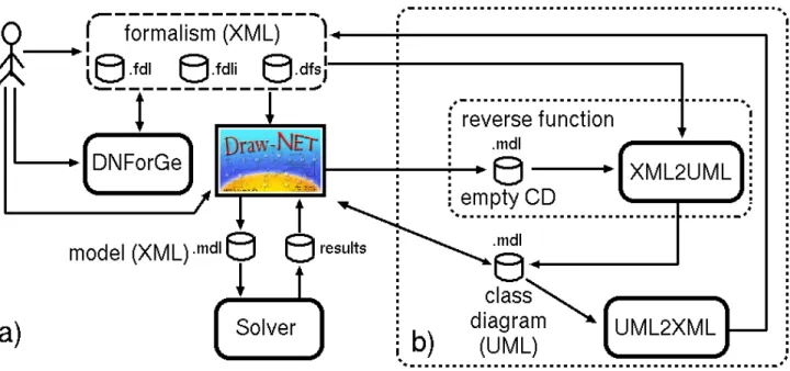
DMS is a Java-based framework exploiting the DNlib library [4, 5]. The general architecture of DMS is composed by the following main levels (Fig. 1.a).
2.1
The formalism level
The formalism level defines all the primitives that can be used to design a model. A formalism is defined as the tuple F = {E, P, C, S, H, TP} where
• E is the set of Elements; • P is the set of Properties; • C is the set of Constraints;
• S is the structure function associating each element to its properties;
• H is the inheritance function setting that one or more elements inherit the properties of a spe-cific (abstract) element;
• TP is the property typing function setting the type of each property.
Elements correspond to the possible nodes and arcs in the model. For example, in the Petri Net (PN) formalism [3], the elements are places, transitions, input/output arcs.
Propertiesare the attributes associated with an element. For example, in PN, the properties of a place are the initial number of tokens (or initial marking) and the mean number of tokens (a measure); a property of a transition is its throughput (mean number of tokens moved by the transition); a property of an arc is its weight (number of tokens moved through the arc). Moreover, an element has graphical properties (shape, size, color, etc.). Properties are typed: they can only contain values of a specific
type (integer, float, string, Boolean, etc.); for example, the initial marking property is integer; the throughput property is float.
Constraints are logical propositions that describe required consistency relations among elements and properties of a model. For example, in a PN, constraints tell that an arc can only connect places to transitions, and transitions to places.
Through DNForGe the user can manipulate the definition of a formalism and automatically gener-ate the corresponding three XML files containing the elements, their properties (including the graph-ical ones), and the solver(s) associated with the formalism. An expert user may avoid the use of DNForGe and directly manipulate the XML files (Fig. 1.a).
2.2
The model level
The model level describes a system using the primitives defined in the formalism to specify a model which is defined by the tuple M = {F, I, m0, T, V } where
• F is the formalism;
• I is the set of element instances (every i ∈ I represents an instance of an element of F ); • m0 ∈ I is the main element;
• T is the element typing function associating i ∈ I with the formalism element to which i corresponds (the element must not be abstract);
• V is the assignment function which specifies the property values (V (i, p) is the value of property p of instance i ∈ I).
The user exploits Draw-Net to select a formalism among the available ones, load its definition from the XML files, and design models conforming that formalism (Fig. 1.a). For example, the PN model of the producer/consumer system (Fig. 4) is composed by two transitions (representing the producer and the consumer respectively) and one place (representing the buffer).
2.3
The solver level
The solver level concerns the analysis or the simulation of the model. Still by means of Draw-Net the user can set the results to compute, save the model into one XML file, and execute the solver on the model. For instance, the user may require the analysis of the PN model in order to compute the mean number of tokens inside the place representing the buffer. The results produced by the solver can be shown by Draw-Net at the end of the model solution (Fig. 1.a).
3
CD based management of formalisms
Fig. 1.b shows how formalisms are now managed through CD. A “reverse engineering” function has been implemented in order to generate the CD of the existing formalisms. To this aim, the CD formalism has been included in DMS; by means of Draw-Net, the user selects the CD formalism, creates an empty CD model, sets the path of the XML files containing the formalism definition, and executes the XML2UML filter which reads the contents of the XML files and generates the representation of the formalism in terms of classes. The resulting CD is saved into a file (still in XML format). At this point, the user can open the CD as an ordinary model, and edit the formalism by manipulating the CD.
Figure 1: a) DMS general architecture. b) CD based management of formalisms.
When the changes to the CD have been completed, the user saves the CD, and executes the UML2XML filter which generates the three XML files containing the formalism specification ac-cording to the classes in the CD. The updated version of the formalism can be used to design models. If the formalism needs to be edited again, this can be done exploiting its CD, in the same way just de-scribed, or by resorting to DNForGe (Fig. 1.a); the contents of the XML files containing the formalism specification, maintain the same format with both solutions.
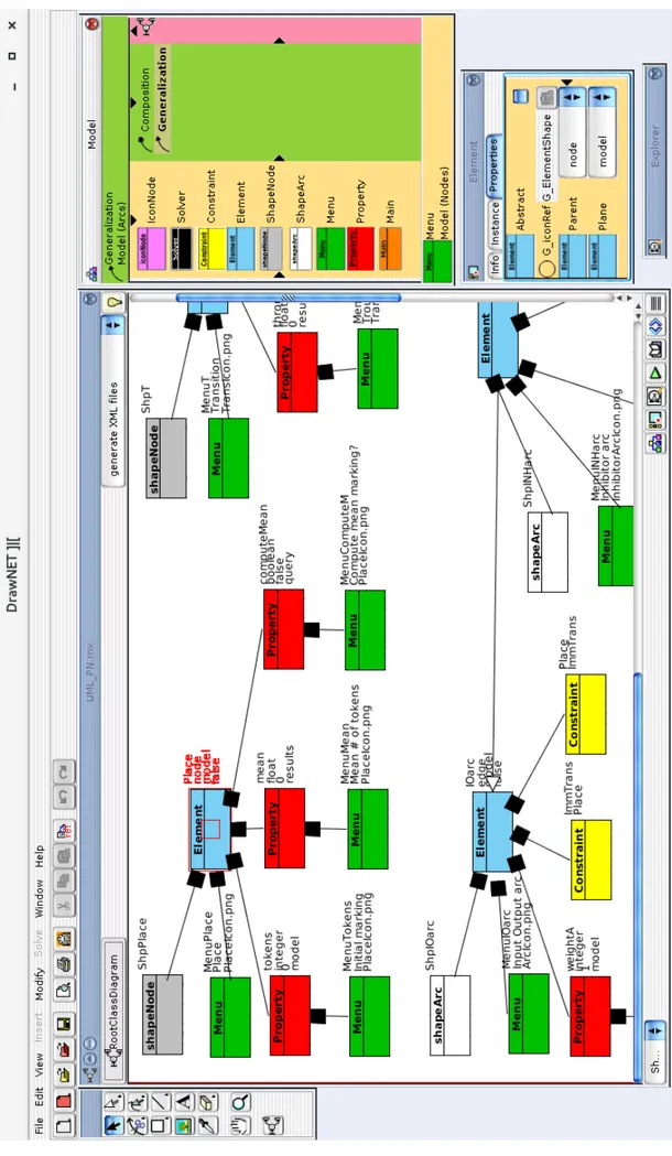
If a new formalism is needed, by means of Draw-Net, the user selects the CD formalism, creates an empty CD model, and inserts all the necessary classes, as shown in Fig. 2 for the PN formalism; then the user saves the CD, and finally executes the UML2XML filter.
3.1
Types of classes in the CD
In UML, a CD specifies a set of classes, where a class acts as a template defining the common attributes of a set of objects (instances); a class is graphically represented by a rectangle. Multiple types of arcs are available, but in this work, only two of them are applied:
• the composition arc indicates that the objects of a class (container) are composed by objects of other classes (a diamond points the container class);
• the generalization arc is used to express that a class is the specialization of a parent class (a closed triangle points the parent class).
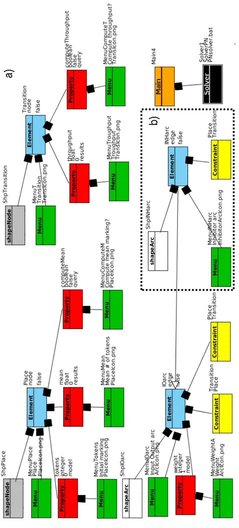
Fig. 3.a shows the complete CD representing the existing PN formalism, obtained from the XML files, by means of the “reverse engineering” function. This CD will be used as a running example during the presentation of the types of classes representing the definition of a formalism. All the classes have an attribute called Id (string) where we can assign a name to the class. In order to be graphically distinguishable, the types of classes have different colours:
Main (orange) represents the main element m0(Sec. 1). An instance of this class in the model will
correspond to the model itself. Only one class of this type can be present in the CD. This class has no attributes.
Solver (black) is used to set the reference to a solver. The CD contains as many Solver classes as the number of solvers associated with the formalism. Each Solver class is connected to the Main class by means of a composition arc because a solver concerns the whole model. The Solver class is characterized by the following attributes necessary to execute the solver:
• Command (string) contains the name of the executable file implementing the solver; • CommandPath (string) contains the path to find the executable solver;
• Parameters (string) contains possible arguments to be passed to the executable file.
Example. In Fig. 3.a, one solver is connected to the main element; in particular, the executable file is PNsolver.bat.
Element (blue) represents a type of node or a type of arc that can be used in the model. This class has the following attributes:
• Abstract (Boolean) indicates whether the element is abstract or not (in the first case, it cannot be instanced in the model and can only be a generalization of other elements);
• Parent (enumeration) can be equal to “node” or “edge”.
Example. In Fig. 3.a, three Element classes represent the possible elements in a PN; the attribute Parentis set to “node” in the classes called Place and Transition, and is set to “edge” for the class IOarc(input/output arc). For all the three classes, the attribute Abstract is set to false.
Property (red) represents a property of an element (possibly the main one), such as the initial marking of a place in a PN. A Property class is connected to the corresponding Element class (or the Mainclass) by means of a composition arc; in this way, the structure function (Sec. 2) is represented. The attributes of the Property class are:
• Default value (string) contains the initial value of the property (if necessary);
• Type (enumeration) can be set to “integer”, “float”, “string”, “Boolean”, “enumeration”, or “fixedArray” (property type function (Sec. 2));
• Size is used to the set the dimension of the array when Type is set to “fixedArray”;
• Plane (enumeration) can be set to “model”, “query”, or “result”, in order to express that the property will be used to characterize the element, require the computation of a certain measure by the solver, or show the corresponding result, respectively.
The inheritance function(Sec. 2), modelled by the generalization arc, allows an element to inherit the properties of another element, possibly an abstract one.
Example. The element Place has three properties: tokens defines the initial marking of the place, its type is integer, its default value is 0, and is on the model plane; computeMean specifies whether the solver has to compute the mean number of tokens or not, its type is Boolean, its default value is false (not to be computed), and is on the query plane; finally, mean, is used to show the value returned by the solver (Fig. 1.a), so its type is float, and is on the result plane. The properties of the element Transition are computeThroughput (query plane) and throughput (result plane). The element IOarc has the property weight on the model plane. In Fig. 3.b, the Element class INHarc (inhibitor arc) is added to the existing PN formalism. In particular, the property weight of IOarc is inherited by INHarc, by means of the generalization arc from INHarc to IOarc.
Constraint (yellow) has two attributes, From (string) and To (string), where we write the names of the types of node that an arc can connect in the model. Each Constraint class is connected to the Elementclass representing the type of arc.
Example. IOarc has two constraints establishing that this kind of arc can go from a transition to a place, or from a place to a transition. INHarc has one constraint: from a place to a transition.
Menu (green) establishes how an element or a property is displayed in the menu panels of Draw-Net. This class has two attributes, Icon (string) and Label (string), setting the path to an image file, and a description, respectively. Each Menu class is connected to the corresponding Element or Prop-erty.
Example. The property tokens of the element Place will appear in the property menu panel of Draw-Neton a line composed by the icon PlaceIcon.png and the label “initial marking”; the property com-puteMeanwill appear on a line composed by same icon and the label “Compute mean marking?”; the property mean will have the label “Mean # of tokens” (Fig. 4).
shapeNode (grey) describes how a specific node graphically appears in the drawing area of Draw-Net. The attributes are: Shape, FillColor, FillStyle, StrokeColor, StrokeStyle, rotation, size_x, size_y. A ShapeNode class is connected to the corresponding Element class.
Example. The shape of a place is an ellipse with size 24 px x 24 px, black stroke color, and white fill color. The shape of a transition is a rectangle with size 24 px x 4 px, black stroke color, and black fill color.
shapeArc describes how a specific arc graphically appears in the drawing area. Its attributes define aspects such as the colour, the style, and the width.
Example. An IOarc is a black continuous line ending with a black triangle. The INHarc instead, ends with a white small circle.
3.2
Building the system model
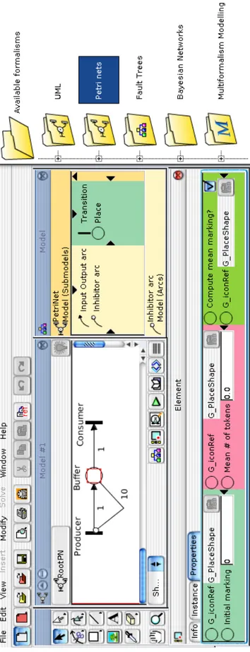
The CD defining the PN formalism, has been edited by means of Draw-Net: after the introduction of the inhibitor arc (Fig. 3.b), the updated XML definition of PN can be automatically generated by the UML2XML filter. Then, still by means of Draw-Net, we can select the PN formalism, and build the PN model of the producer/consumer system (Fig. 4). In particular, it contains: one instance of the Elementclass Place in order to model the buffer; two instances of Transition to produce and consume items (tokens) in the buffer (place); two instances of IOarc to move tokens; one instance of INHarc to disable the production of tokens. In particular, the property tokens of the place is set to 0 (the buffer is initially empty); the property weight is equal to 1 for both input/output arcs (one token is produced or consumed after the firing of a transition); the property weight is equal to 10 for the inhibitor arc, in order to suspend the production of tokens when the content of the buffer reaches 10 items.
4
Conclusions and future work
DMS is a customizable framework supporting any graph-based formalism. The CD based definition of formalisms provides a graphical and intuitive way to manage existing and new formalisms. In this way, the model designer can exploit a familiar language such as UML, and avoids manipulating XML files or learning how DNForGe works. Several types of classes permit to distinguish the primitives composing a formalism; the CD acts as a “meta-model” and can be handled by Draw-Net itself, without the support of UML editors. To this aim, the CD formalism and two filters (UML2XML and XML2UML) have been introduced in DMS. An application example has been shown: the PN
formalism has been defined as a CD (Fig. 3); then the PN model of the producer/consumer system has been designed according to that formalism (Fig. 4).
DMS was designed to deal with single-formalism models, such as PN models, and multi-formalism models [16], i.e. container models composed by several sub-models, each conforming to a different formalism [4, 5]. At the moment, the CD representation does not deal yet with multi-formalism, but this can be faced as future work. Another development can be the definition of other types of con-straint, possibly involving properties; for instance, the initial marking of a place cannot be negative.
Acknowledgements
The author would like to thank the B.Sc. candidates Marina Martinotti, Valentina Libralesso, and and Mattia Scinaldi for implementing the filters UML2XML and XML2UML under his supervision, and prof. Marco Gribaudo for the development and the maintenance of Draw-Net during the years.
References
[1] D. C. Schmidt. Model driven engineering, guest editor’s introduction. IEEE Computer, Special Issue on Model Driven Engineering, pages 25–31, February 2006.
[2] D. Deavours, G. Clark, T. Courtney, D. Daly, S. Derisavi, J. Doyle, W. Sanders, and P. G. Webster. The Möbius Framework and its Implementation. IEEE Transactions on Software Engineering, 28(10):956–969, 2002.
[3] R.A. Sahner, K.S. Trivedi, and A. Puliafito. Performance and reliability analysis of computer systems: an example-based approach using the SHARPE software package. Kluwer Academic Publisher, 1996.
[4] M. Gribaudo, D. Codetta-Raiteri, and G. Franceschinis. Draw-Net, a customizable multi-formalism multi-solution tool for the quantitative evaluation of systems. In International Con-ference on Quantitative Evaluation of Systems, pages 257–258, Turin, Italy, September 2005. [5] D. Codetta-Raiteri, G. Franceschinis, and M. Gribaudo. Defining formalisms and models in the
Draw-Net modeling system. In International Workshop on Modelling of Objects, Components and Agents, pages 123–144, Turku, Finland, June 2006.
[6] M. Gribaudo. FSPNEdit: A fluid stochastic Petri net modeling and analysis tool. In Tools of International Multiconference on Measurements Modelling and Evaluation of computer Com-munication Systems, pages 24–28, Aachen, Germany, September 2001.
[7] M. Beccuti, D. Codetta-Raiteri, G. Franceschinis, and S. Haddad. A framework to design and solve markov decision well-formed net models. In International Conference on Quantitative Evaluation of Systems, pages 165–166, Edinburgh, UK, Sept. 2007.
[8] E. Naumovich, S. Bernardi, and M. Gribaudo. ITPN-PerfBound: A performance bound tool for interval Time Petri Nets. In International Conference on Tools and Algorithms for the Construc-tion and Analysis of Systems, pages 50–53, 2009.
[9] A. Bobbio, D. Codetta-Raiteri, S. Montani, and L. Portinale. Reliability analysis of systems with dynamic dependencies. In Bayesian Networks: A Practical Guide to Applications, pages 225–238. John Wiley & Sons, March 2008.
[10] D. Codetta-Raiteri and L. Portinale. Approaching dynamic reliability with predictive and di-agnostic purposes by exploiting dynamic bayesian networks. Journal of Risk and Reliability, 228(5):488–503, 2014.
[11] D. Codetta-Raiteri and L. Portinale. A Petri net-based tool for the analysis of generalized contin-uous time Bayesian networks. In Theory and Application of Multi-Formalism Modeling, pages 118–143. IGI Global, 2013.
[12] D. Codetta-Raiteri. Extended fault trees analysis supported by stochastic Petri nets. PhD thesis, Dipartimento di Informatica, Università di Torino, November 2005.
[13] L. Portinale, A. Bobbio, D. Codetta, and S. Montani. Compiling dynamic fault trees into dy-namic Bayesian nets for reliability analysis: the Radyban tool. In Bayesian Modeling Applica-tions Workshop, volume 268 of CEUR Workshop Proceedings, Vancouver, Canada, July 2007. [14] M. Beccuti, D. Codetta-Raiteri, G. Franceschinis, and S. Haddad. Non deterministic Repairable
Fault Trees for computing optimal repair strategy. In International Conference on Performance Evaluation, Methodologies and Tools, Athens, Greece, October 2008.
[15] T. Pender. UML Bible. Wiley Publishing Inc., 2003.
[16] V.Vittorini, M. Iacono, N. Mazzocca, and G. Franceschinis. The OsMoSys approach to multi-formalism modeling of systems. Journal of Software and System Modeling, 3(1), 2004.