CFD ANALYSIS OF AN INNOVATIVE VACUUM MICRO-GRIPPER
Urbano D.G.1 Noventa G.1 Fassi I.2 Fontana G.2 Ghidoni A.1 Legnani G.1 Ruggeri S.2 and Lezzi A.M.1 * 1 Dept. of Mechanical and Industrial Engineering, University of Brescia
Via Branze 38, 25123 Brescia, Italy
2 Institute of Intelligent Industrial Technologies and Systems for Advanced Manufacturing, National Research Council of Italy,
Via A. Corti 12, 20133 Milan, Italy *Author for correspondence E-mail: [email protected]
ABSTRACT
A new type of vacuum microgripper is considered. An automatic release device inserted in the gripper body allows to overcome adhesion forces that can prevent detachment of the object to be handled. A CFD analysis of a simplified model of the device is presented. The goal is to evaluate the lifting force on the release device as a function of geometric parameters, an important information for design of this class of microgrippers. A reference geometry has been firstly investigated using a high-fidelity approach, i.e. a Large Eddy Simulation. The results have been used to validate a cheaper CFD approach based on the RANS solution. Then through steady RANS computations a dataset has been obtained varying geometric parameters of the device. Trends of the lifting force in terms of geometry modification are presented and discussed. All calculations have been performed with OpenFOAM®.
1. INTRODUCTION
The continuing trend towards miniaturization which characterizes many industrial and non-industrial sectors (electronics, mechanics, bioengineering, biology, medicine, etc.) requires the design of technologies and devices to manufacture and to assemble components at the micro-scale.
Microgrippers are devices used in order to grasp, move, and handle very small objects. They are widely used in several fields, like e.g. microelectronics, where it is important to place and assemble together microcomponents in complex structures with high precision and velocity. In this contest, automatic manipulation devices play an essential role.
Several types of grippers based on different grasping mechanisms are currently used. For example, electrostatic forces caused by charge difference between the gripper and the object [1]–[3]. Capillarity forces exerted by a liquid interposed between the gripper and the object to be moved [4], [5]. Van der Waals forces as well as cryogenic gripping are other grasping mechanisms used in some applications [6], [7].
Vacuum microgrippers are among the most popular types of grippers. The simplicity of their working principle and structure make this kind of grasping device cheap and easy to replace. Moreover, they allow precise handling of microparts and a high degree of accurancy. However, when the mass of the objects to be handled becomes too small vacuum microgrippers suffer from the effect of adhesive forces, that can overcome the object weight force, preventing or strongly affecting the release.
Different strategies have been set up to deal with this issue. These release techniques can be classified into passive and active strategies. The formers are based on the possibility to create suitable gripping features to reduce the adhesive forces between the gripper and the object, for example, coating with the same material both of them to reduce contact interaction [8]. Active techniques, instead, introduce additional forces to overcome adhesion: mechanical vibrations [9], electric fields [10], positive pressure pulses [11].
In this work a new kind of vacuum microgripper, patented by some of the authors and described in Sec. 2, is considered. The microgripper incorporates an automatic release device which is controlled by gravity and aerodynamic forces. One research goal is to develop a numerical model able to predict the performance of the gripper, i.e. how the aerodynamic force acting on the release device depends on the geometry of the device. Such a model would help in the preliminary design of this class of grippers.
A series of simulations are presented changing the values of some design variables within a set optimized using Design of Experiments (DOE) techniques. Since the number of simulations carried out before the paper submission deadline is not yet sufficiently large only preliminary considerations will be presented in Sec. 6.
2. VACUUM MICROGRIPPER WORKING
MECHANISM
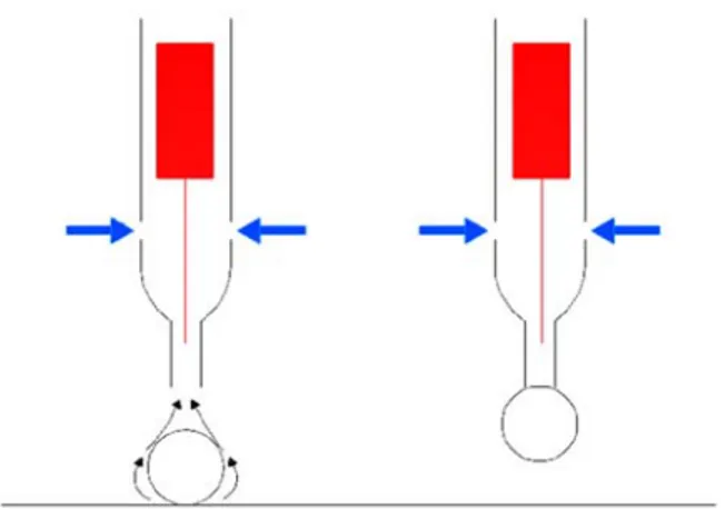
The vacuum microgrippers considered in this work can be represented as hollow cylinders (gripper body): at one end a small diameter cannula is inserted in the gripper body; at the other end a negative gauge pressure (∆p) is imposed through connection to a vacuum pump or an ejector. The pressure difference between the environment and the gripper inside causes an air flow towards the cannula end and then through the cannula and the gripper body. If the cannula end is close enough to the object to be grasped the drag force exerted by the air flow on the object itself will carry it against the cannula (aspiration phase). The drag force must be larger than the weight force acting on the object (see Figs. 1 left and 2 left).
When the object sticks against the cannula end (sticking phase) the forces acting on it are Wo, Fp, and Fa, that is: the object
weight (downwards)
|∆ |
where is the cannula inner section area, and the adhesion forces (upwards), .
In order to keep the object attached to the cannula the following inequality must hold
When the pressure difference is removed, 0, and the object is released (release phase) only if its weight overcomes adhesion forces: that may not be the case for mass below a threshold depending on many factors [12], [13].
To prevent this problem modified versions of the basic vacuum microgripper described above have been proposed. Some of the authors of this paper patented a microgripper with a releasing mass inside the gripper body (in red in Fig. 1). The releasing mass is equipped with a small rod slightly longer than the cannula and with diameter smaller than the cannula inner diameter. During the aspiration phase the drag force exerted on the releasing mass by the flow through the gripper body will lift it. When the object hits and sticks to the cannula end, the flow is blocked and the releasing mass falls down. In order to keep the object attached to the cannula, now Eq. (4) must be satisfied with an additional term on the right side to keep the releasing mass into account
Although the pressure force, as well as the sucking forces on the object and on the releasing mass can be controlled through the gauge pressure, in this version of the device the mass of the releasing mass should be of the same order of that of the object, . There are experimental evidences [13] that the increased mass does not guarantee the actual release of the object, that is the following disequality is not always satisfied
In order to allow releasing inserts of mass much larger than that of the object, a modified version of the gripper has been proposed in [12], [14]. The new layout is sketched in Fig. 2. Thanks to air inlets on the lateral surface of the gripper body, the flow sucking the object is uncoupled from the flow lifting the releasing mass. On one hand, increasing the lateral hole inlet area allows to increase the air flow rate inside the device and the lifting force on the releasing mass. On the other hand, during the sticking phase when the object is attached to the cannula blocking the sucking flow, the air streams through the lateral inlets will still be flowing and lifting the releasing mass.
Figure 1 Patented microgripper layouts with releasing mass only
Figure 2 Patented microgripper layouts with releasing mass and lateral holes
In this way an anticipated detachment of the object is avoided. When the gauge pressure is brought to zero the releasing mass falls, pushing the object away from the cannula: since the mass of the insert can be chosen large enough to overcome any adhesion force the gripper releasing efficiency will tend to 1.
Care must be taken in choosing the lateral inlets area, as well as the thickness of the annulus between the releasing mass and gripper body wall, or the length of the releasing mass: for inlets area too small the air flow decreases significantly and the drag force is not enough to lift the releasing mass, whereas inlets area too large may induce a large air flow through the gripper that reduces the grasping performance of the gripper[13].
A semi-empirical model was proposed in [12] and [13] to find a relation among the gauge pressure, the air flow rate through the gripper body, the drag force on the releasing mass, and three geometric parameters: the lateral holes diameter, the releasing mass length, and the gripper body inner diameter. Coefficients in the model were determined by fitting the results (2)
(3)
(4)
of a limited number of simulations. Here, a new set of simulations is presented: agreement of the results with those in [12] and [13] is acceptable, however unsteady LES simulation for one configuration has been performed with a two-fold goal. Since reliable experimental results on the microgripper are not available yet, these simulations were meant to assess accuracy of the two sets of numerical data. In addition, since the two sets of simulations were obtained on the assumption of steady flow, it was considered necessary to assess the reliability of the assumption through some unsteady simulations. Finally, a DOE approach was planned both to select the parameter combinations to be tested and to interpolate numerical data to obtain correlations for air flow through the gripper and for total lifiting force on the releasing mass. Unfortunately the number of simulations carried out before the paper submission deadline is not sufficient for a reliable application of DOE methods: therefore only preliminary considerations will be presented in Section 6.
3. SIMPLIFIED GRIPPER MODEL
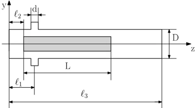
Most of the variables considered in this study are specified in Fig. 3.
Figure 3 Nomenclature for the study of microgripper The mass flow rate through the gripper, q2, is equal to the sum of the mass flow rate through the cannula, q0, and of the mass flow rate through the two lateral holes, 2q1.
q2 = 2q1+ q0
Since the cannula section area, A0, is much smaller than the lateral holes area, A1, A0 << A1, q0 is expected to be much smaller than q1 and can be neglected. Therefore to determine the force acting on the releasing mass the simplified geometry in Fig. 4 is adopted: the cannula is not considered and the gripper body is bounded by a solid wall. The soundness of this assumption was assessed in a set of preliminary simulation with and without cannula [13]. The geometry investigated has two symmetry planes: with reference to Fig. 4, they are 0 and 0. Taking advantage of one of them only half gripper has been modelled in the CFD analysis ( 0 .
Figure 4 Simplified gripper model for CFD simulation In what follows numerical results of mass flow rate and force refer to half gripper, that is q = q1 is the air flow through one lateral hole, and Fz is the force on half releasing mass.
In the prototype presented in [12] and [13] a mechanical stop prevents the releasing mass to be lifted beyond an assigned height. In this model the releasing mass is considered fixed at the maximum allowed height. The distance between the gripper bottom wall and the air inlet axis is ℓ 3.25 mm, whereas that between the gripper bottom wall and the releasing mass is ℓ 2.1 mm. The distance between the gripper bottom wall and the outlet is ℓ 76.3 mm. Other lengths are specified in Tab. 1.
4. PRELIMINARY DOE ANALISYS
DOE analysis is planned to process numerical data, however, being not yet available at this time a sufficient number of simulations to perform a full DOE analysis, only a partial set of data is presented.
Final goal is a full factorial design, using 3 levels for geometrical factors (d, L, D) and 3 levels for the outlet pressure (p3). According to the size of the device, a region of interest and appropriate numerical values have been identified for each level, as shown in Tab 1. Factor Levels d [mm] 0.59 0.69 0.77 L [mm] 16.2 24.2 32.2 D [mm] 3.2 3.4 3.6 p3[kPa] 70 80 90
Table 1 Factors and levels for DOE analysis
Up to now a total of 45 simulations out of 81 have been performed and are the basis for the current analysis.
5. CFD ANALYSIS
The simplified gripper geometry presented in Sec. 3 has been extensively investigated using a Computational Fluid Dynamics (CFD) tool, the open source CFD toolbox OpenFOAM®[15], [16]
Different gripper configurations have been considered, as described in Sec. 4, being interested in determining the air mass flow rate through the lateral hole, and the lifting force on the releasing mass.
The flow-field inside the gripper has been computed using the compressible steady state solver rhoSimpleFoam, solving the
Figure 5 Grid of the computational domain
RANS (Reynolds Average Navier Stokes) equations coupled with SST turbulence model. The meshes for each configuration have been generated using the open source software SALOME [17] , with a target number of elements around 1 million, greater than the value suggested by the grid independence analysis proposed in [13], being this mesh tetra-dominant. In fact, a hybrid unstructured grid has been used, consisting of prismatic layer in the boundary layer regions and tetrahedra elsewhere. The size of the elements adjacent to the solid walls is equal to a non-dimensional distance y+=1, to compute the boundary layer accurately up to the wall. Figure 5 shows a detail of a computational mesh near the lateral hole.At the domain inlet the total temperature (T01=293 K), total pressure (p01=100 kPa), flow angle (the velocity vector is normal to the inlet surface), and turbulence intensity Tu1=4% are prescribed, while at the outflow a static pressure (p3) is set. Adiabatic wall boundary conditions are applied to all domain walls, while a symmetry condition (zero normal gradients for all variable and zero normal velocity) is applied to the symmetry plane. The second-order upwind discretization scheme is applied to the divergence of the velocity and energy, while the first-order upwind scheme is applied to the turbulent quantities. The Laplacian terms are evaluated using a linear second-order bounded central scheme, while a central differencing method approximates the gradient term. The proposed computational approach (RANS) has been first validated on a reference geometry (L = 24.2 mm, d = 0.77 mm, and D = 3.4 mm) for an outlet static pressure p3=90 kPa. Being not available experimental data, the mass flow rate and the force applied on the releasing mass predicted by RANS have been compared with the results obtained with a more accurate approach, i.e. the Large Eddy Simulation (LES). LES approach implemented in the OpenFOAM solver rhoPimpleFoam have been used, and a one-equation eddy viscosity model has been considered as subgrid scale (SGS) model.
6. RESULTS AND DISCUSSION
The RANS approach has been first validated with the LES, computing the flow field for the reference geometry and comparing the predicted massflow and lifting force on the releasing mass. Table 2 summarizes the results, showing a difference between RANS and LES around 8% and 23% for the massflow and force prediction, respectively. The comparison suggests that the unsteady effects are negligible in the evaluation
q [kg/s] Fz [N]
RANS 4.92x10⁻⁵ 6.74x10⁻³
LES 5.35x10⁻⁵ 8.77x10⁻³
Table 2 Comparison of the predicted massflow and lifting force on the releasing mass for RANS and LES approaches
of q and Fz. and justifies the use of the less accurate steady RANS
approach, considering the huge computational saving.
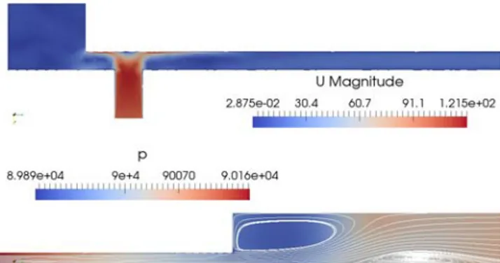
The flow field inside a gripper geometry (d=0.77mm, L=32.2mm, D=3.6mm) considered in the DOE analysis is first analyzed for all the outlet pressures, p3=(90kPa, 80kPa, 70kPa). As expected, the velocity at the inlet increases with the -Δp = p0 -p3 across the gripper, as shown in Fig.s 6, 7, 8 (top). Figures 6, 7, 8 (bottom) show a detail of the zone at the end of the releasing mass. Notice that the recirculation bubble length depends on the -Δp, increasing for greater -Δp. On the outer wall a flow detachment appears, related to the local adverse pressure gradient created by the outlet losses, as shown by pressure contours.
Figure 6Velocity (top) and pressure (bottom) contours, d=0.77mm, L=32.2mm, D=3.6mm, p3=90kPa
Figure 7Velocity (top) and pressure (bottom) contours, d=0.77mm, L=32.2mm, D=3.6mm, p3=80kPa
Figure 8Velocity (top) and pressure (bottom) contours, d=0.77mm, L=32.2mm, D=3.6mm, p3=70kPa
The detachment is more evident for small -Δp, being the flow slower.
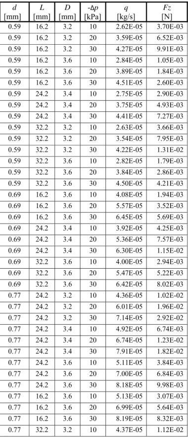
Post processing of CFD simulations provides both the value of air flow rate, q, and resultant force acting on the releasing mass, as shown in Tab. 3.
d
[mm]
L
[mm]
D
[mm]
-
Δp
[kPa]
q
[kg/s]
Fz
[N]
0.59 16.2 3.2 10 2.62E-05 3.70E-03 0.59 16.2 3.2 20 3.59E-05 6.52E-03 0.59 16.2 3.2 30 4.27E-05 9.91E-03 0.59 16.2 3.6 10 2.84E-05 1.05E-03 0.59 16.2 3.6 20 3.89E-05 1.84E-03 0.59 16.2 3.6 30 4.51E-05 2.60E-03 0.59 24.2 3.4 10 2.75E-05 2.90E-03 0.59 24.2 3.4 20 3.75E-05 4.93E-03 0.59 24.2 3.4 30 4.41E-05 7.27E-03 0.59 32.2 3.2 10 2.63E-05 3.66E-03 0.59 32.2 3.2 20 3.54E-05 7.95E-03 0.59 32.2 3.2 30 4.22E-05 1.31E-02 0.59 32.2 3.6 10 2.82E-05 1.79E-03 0.59 32.2 3.6 20 3.84E-05 2.86E-03 0.59 32.2 3.6 30 4.50E-05 4.21E-03 0.69 16.2 3.6 10 4.08E-05 1.94E-03 0.69 16.2 3.6 20 5.57E-05 3.52E-03 0.69 16.2 3.6 30 6.45E-05 5.69E-03 0.69 24.2 3.4 10 3.92E-05 4.25E-03 0.69 24.2 3.4 20 5.36E-05 7.57E-03 0.69 24.2 3.4 30 6.30E-05 1.15E-02 0.69 32.2 3.6 10 4.00E-05 2.94E-03 0.69 32.2 3.6 20 5.47E-05 5.22E-03 0.69 32.2 3.6 30 6.42E-05 8.02E-03 0.77 24.2 3.2 10 4.36E-05 1.02E-02 0.77 24.2 3.2 20 6.01E-05 1.96E-02 0.77 24.2 3.2 30 7.14E-05 2.92E-02 0.77 24.2 3.4 10 4.92E-05 6.74E-03 0.77 24.2 3.4 20 6.74E-05 1.23E-02 0.77 24.2 3.4 30 7.91E-05 1.82E-02 0.77 24.2 3.6 10 5.11E-05 3.84E-03 0.77 24.2 3.6 20 7.00E-05 6.84E-03 0.77 24.2 3.6 30 8.18E-05 9.98E-03 0.77 16.2 3.6 10 5.13E-05 3.07E-03 0.77 16.2 3.6 20 6.99E-05 5.64E-03 0.77 16.2 3.6 30 8.19E-05 8.32E-03 0.77 32.2 3.2 10 4.37E-05 1.12E-02 0.77 32.2 3.2 20 6.06E-05 2.18E-02 0.77 32.2 3.2 30 7.19E-05 3.24E-02 0.77 32.2 3.6 10 5.13E-05 3.89E-03 0.77 32.2 3.6 20 7.00E-05 6.89E-03 0.77 32.2 3.6 30 8.18E-05 9.76E-03 0.77 16.2 3.2 10 4.41E-05 8.47E-03 0.77 16.2 3.2 20 6.13E-05 1.61E-02 0.77 16.2 3.2 30 7.22E-05 2.42E-02Table 3 Computational air flow rate, q, and resultant force on releasing mass, Fz.
As expected a greater lateral hole diameter, d, increases the air flow rate flowing through the gripper.
Also the force on the releasing mass increases with the hole diameter d (Fig. 9). Indeed, a greater air flow rate through the annulus, on one hand increases the shear stresses on the releasing mass lateral surface and the skin friction component, Fv,z of Fz; on the other hand it causes a larger pressure drop when fluid leaves the annulus, increasing the pressure difference between the two basis of the releasing mass and the pressure component of the force, Fp,z.
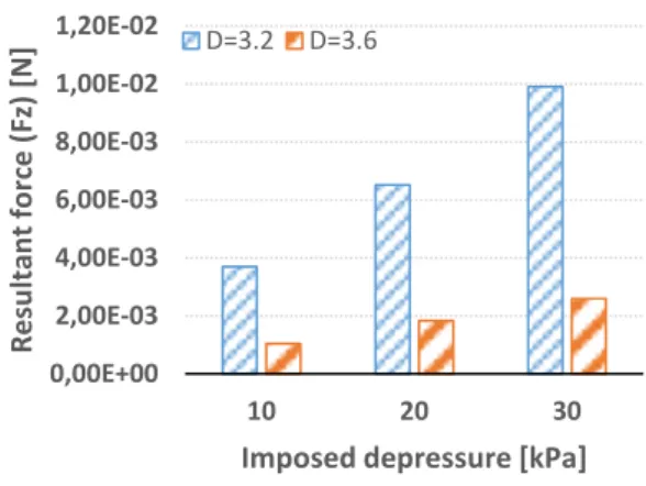
Figure 9 Dependence of Fz on lateral hole diameter d It is interesting to note that force Fz is strongly dependent on the diameter D (Fig. 10). In particular, when the value of D increases, force decreases significantly. Both pressure Fp,z and skin friction component Fv,z decrease: a greater annulus area reduces shear stress on the lateral surface and the difference of pressure between the basis of the releasing mass. The length of the releasing mass L does not affect the value of mass flow rate, whereas has an influence on the value of the lifting force (Fig. 11). In particular, the skin friction component increases with L.
0,00E+00 1,00E‐03 2,00E‐03 3,00E‐03 4,00E‐03 5,00E‐03 6,00E‐03 7,00E‐03 8,00E‐03 9,00E‐03 10 20 30 Re sult ant fo rce (Fz ) [N] Imposed depressure [kPa] d=0.59 d=0.69 d=0.77 L = 16.2 mm ‐ D = 3.6 mm
Figure 10 Dependence of Fz on diameter D.
Figure 11 Dependence of Fz on releasing mass length L. 7. CONCLUSIONS
A numerical investigation of lifting force on the releasing mass of an automatic release device for vacuum microgrippers has been performed and presented. The lifting force determines the maximum releasing mass mrm that can be kept lifted during the
sticking phase. During the release phase this mass must overcome the adhesion force on the object grasped. Although the result dataset is not yet large enough to perform a full DOE analysis and to determine correlations in terms of geometric parameters of the device, trends of the lifting force for varying d, L, and D have been highlighted. Particularly strong is the dependence on D, that is on the thickness of the annulus between releasing mass and gripper body, whereas d and/or L, could be modified for fine tuning. In any case during the release phase the device allows to apply an additional force to the object up to few cN which should overcome any adhesion force preventing the object detachment from the gripper.
REFERENCES
[1] Tsuchiya, K., Murakami, A., Fortmann, G., Nakao, M., & Hatamura, Y. (1999). Microassembly and microbonding in nano manufacturing world. In Microrobotics and Microassembly (Vol. 3834, pp. 132-141).
[2] Enikov, E. T., & Lazarov, K. V. (2001, October). Optically transparent gripper for microassembly. In Microrobotics and
Microassembly III (Vol. 4568, pp. 40-50).
[3] Hesselbach, J., Buettgenbach, S., Wrege, J., Buetefisch, S., & Graf, C. (2001). Centering electrostatic microgripper and magazines for microassembly tasks. In Microrobotics and
Microassembly III (Vol. 4568, pp. 270-278).
[4] Grutzeck, H., & Kiesewetter, L. (2002). Downscaling of grippers for micro assembly. Microsystem Technologies, 8(1), 27-31. [5] Bark, C., Binnenbose, T., Vogele, G., Weisener, T., & Widmann,
M. (1998). Gripping with low viscosity fluids. In Proceedings
MEMS 98. IEEE. Eleventh Annual International Workshop on Micro Electro Mechanical Systems. An Investigation of Micro Structures, Sensors, Actuators, Machines and Systems (pp.
301-305). IEEE.
[6] Kochan, A. (1997). European project develops “ice” gripper for micro-sized components. Assembly Automation, 17(2), 114-115. [7] Arai, F., & Fukuda, T. (1997). A new pick up and release method
by heating for micromanipulation. In Proceedings IEEE The
Tenth Annual International Workshop on Micro Electro Mechanical Systems. An Investigation of Micro Structures, Sensors, Actuators, Machines and Robots (pp. 383-388).
[8] Fantoni, G., Santochi, M., Dini, G., Tracht, K., Scholz-Reiter, B., Fleischer, J., & Hansen, H. N. (2014). Grasping devices and methods in automated production processes. CIRP Annals, 63(2), 679-701.
[9] Haliyo, D. S., Regnier, S., & Guinot, J. C. (2003). MAD, the adhesion based dynamic micro-manipulator. European Journal of
Mechanics-A/Solids, 22(6), 903-916.
[10] Saito, S., Himeno, H., & Takahashi, K. (2003). Electrostatic detachment of an adhering particle from a micromanipulated probe. Journal of Applied Physics, 93(4), 2219-2224.
[11] Zesch, W., Brunner, M., & Weber, A. (1997). Vacuum tool for handling microobjects with a nanorobot. In Proceedings of
International Conference on Robotics and Automation (Vol. 2,
pp. 1761-1766).
[12] Ruggeri, S., Fontana, G., Ghidoni, A., Morelli, A., Legnani, G., Lezzi, A. M., & Fassi, I. (2018). A Preliminary Fluid Dynamic Model of a Vacuum Micro-Gripper With Integrated Release System. In ASME 2018 International Design Engineering
Technical Conferences and Computers and Information in Engineering Conference.
[13] Fontana, G., Ruggeri, S., Ghidoni, A., Morelli, A., Legnani, G., Lezzi, A. M., & Fassi, I. (2018). Fluid Dynamics Aided Design of an Innovative Micro-Gripper. In International Precision
Assembly Seminar (pp. 214-225).
[14] S. Ruggeri, G. Fontana, G. Legnani, and I. Fassi, “Design strategies for vacuum micro-grippers with integrated release system,” in ASME 2017 International Design Engineering
Technical Conferences and Computers and Information in Engineering Conference, 2017.
[15] Weller, H. G., Tabor, G., Jasak, H., & Fureby, C. (1998). A tensorial approach to computational continuum mechanics using object-oriented techniques. Computers in physics, 12(6), 620-631. [16] OpenFOAM 4.1, https://openfoam.org, 13 october 2016. . [17] Ribes, A., & Caremoli, C. (2007). Salome platform component
model for numerical simulation. In 31st Annual International
Computer Software and Applications Conference (COMPSAC 2007) (Vol. 2, pp. 553-564). 0,00E+00 2,00E‐03 4,00E‐03 6,00E‐03 8,00E‐03 1,00E‐02 1,20E‐02 10 20 30 Resu ltant fo rce (F z) [N] Imposed depressure [kPa] D=3.2 D=3.6 d= 0.59 mm ‐ L = 16.2 0,00E+00 1,00E‐02 2,00E‐02 3,00E‐02 4,00E‐02 10 20 30 Re sult ant fo rc e (Fz ) [N] Imposed depressure [kPa] L=16.2 L=32.2 d= 0.77 mm ‐ D = 3.2