Prosthesis 2019, 1, 41–53; doi:10.3390/prosthesis1010006 www.mdpi.com/journal/ Article
Prosthetic and Mechanical Parameters of the Facial
Bone under the Load of Different Dental Implant
Shapes: A Parametric Study
Marco Cicciù 1, Gabriele Cervino 1, Antonella Terranova 1, Giacomo Risitano 2,
Marcello Raffaele 2, Filippo Cucinotta 2, Dario Santonocito 2 and Luca Fiorillo 1,3,*
1 Department of Biomedical and Dental Sciences, Morphological and Functional Images, University of
Messina, Policlinico G. Martino, Via Consolare Valeria, 98100 Messina, Italy; [email protected] (M.C.); [email protected] (G.C.); [email protected] (A.T.)
2 Department of Engineering, Messina University, 98100 Messina, Italy; [email protected] (G.R.);
[email protected] (M.R.); [email protected] (F.C.); [email protected] (D.S.)
3 Multidisciplinary Department of Medical-Surgical and Dental Specialties, Second University of Naples,
80141 Naples, Italy
* Correspondence: [email protected]; Tel.: +39-090-2216920
Received: 26 October 2019; Accepted: 12 November 2019; Published: 14 November 2019
Abstract: In recent years the science of dental materials and implantology have taken many steps
forward. In particular, it has tended to optimize the implant design, the implant surface, or the connection between implant and abutment. All these features have been improved or modified to obtain a better response from the body, better biomechanics, increased bone implant contact surface, and better immunological response. The purpose of this article, carried out by a multidisciplinary team, is to evaluate and understand, through the use also of bioengineering tests, the biomechanical aspects, and those induced on the patient's tissues, by dental implants. A comparative analysis on different dental implants of the same manufacturer was carried out to evaluate biomechanical and molecular features. Von Mises analysis has given results regarding the biomechanical behavior of these implants and above all the repercussions on the patient's tissues. Knowing and understanding the biomechanical characteristics with studies of this type could help improve their characteristics in order to have more predictable oral rehabilitations.
Keywords: dental implants; osseointegrated implants; dental prosthesis design; biomechanical
phenomena; dental occlusion; osseointegration; wound healing; immunological; bone tissue; finite element analysis
1. Introduction
The dental implant (also known as endosseous implant) is a surgical-type medical device used to functionally and aesthetically rehabilitate the loss or congenital deficiency of one or more teeth, allowing the support of a prosthetic substitute through direct bone support thanks to a biological process known as osseointegration. The long-term prognosis of dental implants can be considered reliable and predictable, as it can now be based on more than forty years of worldwide clinical experience. The data reported in the literature report variable failure rates, depending on the operating techniques and types used. The type of surface treatment also appears to involve significant differences in the implant survival data. The failures are divided according to the causes, biological, biomechanical, and aesthetic. Biological failures are divided into early and late, depending on the period in which they occur. Early failure is typically linked to a deficient initial osseointegration process following the surgical procedure, more rarely to operational errors in the procedure itself,
while late failures are due to progressive infectious processes affecting the peri-implant tissues and therefore the supporting bone that surrounds the implant (peri-implantitis) [1–6]. Biomechanical failures derive from problems due to overload and functional trauma, which can occur with structural failure at both the implants and the supported prosthetic structures. The direct implant-bone connection linked to the osseointegration process leads to a greater functional load both on the prosthetic elements of the implants and on the antagonist elements that come into contact with the implant prosthetic elements. The lack of the physiological periodontal ligament also implies the absence of the proprioceptive structures that contribute to limiting trauma, through some opportune reflex mechanisms. This explains the tendency to increase mechanical problems over time. Some systems have been proposed to limit these problems by inserting elastic elements in the structure of the plants. There is talk of aesthetic failure when in areas of high aesthetic relevance there are exposures of metal parts, bone dehiscence and gums with retraction of the interdental papillae and the creation of dark triangles below the contact points of the teeth. The success or failure of the implants depends both on the health status of the person receiving it, on any medications taken which have a possible impact with osseointegration, and the condition of the tissues of the mouth [7,8]. The mechanical stress that the implant would encounter during its life must be carefully evaluated. The correct planning of the position and number of implants is fundamental for the long-term preservation of the prosthesis, as the biomechanical forces acting during chewing can be significant. The position of the implant is determined by the position and angle of the adjacent teeth, by laboratory simulations, or by the use of computerized tomography with CAD / CAM simulations and surgical guides [9].
The objective of this study is to evaluate how the geometric and therefore biomechanical characteristics of a dental implant, in addition to having repercussions on the components of the implant, can influence the response of the patient's oral tissues [10–13].
2. Results
The equivalent Von Mises stress distribution at the maximum load during the masticatory cycle has been evaluated. A vertical compressive load was applied on the three different prostheses and after the simulation was performed the obtained data were post-processed. The results are presented adopting a unified color scale for each kind of prosthesis component, ranging from a minimum value in megapascal (MPa), represented by blue color, and a maximum value, represented by red color. In order to show the internal stress arising in the different parts of the finite element models, the stress has been evaluated in section views.
As a first result, it is possible to see how all of the prosthesis components reach a maximum stress value lower than the yielding stress of the titanium (1020 MPa), therefore plasticization and static rupture of the prosthesis are avoided (Figure 1).
Figure 1. Equivalent Von Mises stress results for the complex bone fixture and prosthodontic
attachments: (a) AnyOne® External; (b) AnyOne® Internal; (c) AnyOne® OneStage.
The AnyOne® Internal presents the most stressed area in the abutment, in the abutment-implant connection interface and in the thread of the internal screw (Figure 2b). On the other hand, AnyOne® External and AnyOne® OneStage present the area of maximum stress in the internal screw thread and in the internal contact area between the screw and the abutment (Figure 2 –c).
(a) (b) (c)
Figure 2. Equivalent Von Mises Stress results on the three prosthesis: (a) AnyOne® External; (b)
AnyOne® Internal; (c) AnyOne® OneStage.
The internal screw, thanks to the applied preload, guarantees the correct mechanical joining between the implant and the abutment. For all three internal screws, regardless of the prosthesis geometry, the most stressed areas are located at the contact interface between the head of the screw itself and the abutment hole and also in the first threads of the threading (Figure 3).
(a) (b) (c)
Figure 3. Equivalent Von Mises stress results on the internal screws: (a) AnyOne® External; (b)
AnyOne® Internal; (c) AnyOne® OneStage.
The implant is the joining part responsible for the load transfer between the prosthesis and the bone and it has to be perfectly osseointegrated in order to allow this load transfer. The AnyOne®
External implant presents higher stress in the proximity of the first thread of the internal nut and on the first thread of the external threading (Figure 4a). The AnyOne® Internal implant shows the most stressed area in the internal contact interface with the abutment and in the thread of the internal nut (Figure 4b), while the AnyOne® OneStage implant has lower stress values compared to the other two implants, but located in the same areas (Figure 4c).
(a) (b) (c)
Figure 4. Equivalent Von Mises stress results on the implants: (a) AnyOne® External; (b) AnyOne®
Internal; (c) AnyOne® OneStage.
The abutment must withstand the time-varying forces coming from the masticatory cycle. The AnyOne® External abutment presents the highest stress in the internal contact area with the retaining screw (Figure 5). The AnyOne® Internal abutment has the highest stress in the same contact area of the previous one, but it exhibits also a large stress area in its upper part, where the load is applied (Figure 5b). The AnyOne® OneStage, in adjunction to the internal screw contact area, presents higher stress also in the lower contacting part with the relative implant (Figure 5c).
(a) (b) (c)
Figure 5. Equivalent Von Mises stress results on the abutments: (a) AnyOne® External; (b) AnyOne®
Internal; (c) AnyOne® OneStage.
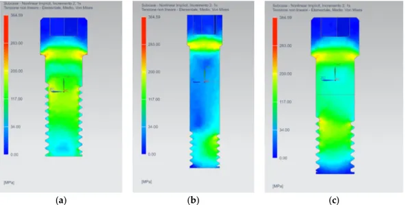
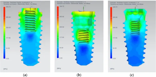
From the analysis of the stress distribution on the bone tissues (Figures 6 and 7), it is possible to see how the AnyOne® External implant stresses a larger part of the cancellous bone, especially the
first threads. On the other hand, the AnyOne® Internal presents a well-defined stressed area around the thread of the implant. The AnyOne® OneStage presents, as the External device, a wide stress area around the threading of the implant with lower stress values for the first threads compared to the other two devices.
(a) (b) (c)
Figure 6. Stress distribution on the cancellous bone for: (a) AnyOne® External; (b) AnyOne® Internal;
(c) AnyOne® OneStage.
As regards cortical tissues, a more homogeneous distribution of the stress for the AnyOne® External and AnyOne® OneStage devices is registered, while greater peaks of stress are exhibited by the AnyOne® Internal prosthesis (Figure 7).
(a) (b) (c)
Figure 7. Stress distribution on the bone tissues (cancellous and cortical) for: (a) AnyOne® External;
(b) AnyOne® Internal; (c) AnyOne® OneStage.
3. Discussion
The finite element analysis is a useful aid for the assessment of stress rising in the bone due to the presence of prosthetic devices. It represents an easy way to investigate complex biomechanical systems instead of experimental techniques that are difficult to apply [14,15]. To perform a reliable simulation, several fundamental parameters have to be taken into account, such as the bone tissues material model, the state of osseointegration of the implant, and the preload of the internal screw. Also, the reverse engineering procedure assumes a fundamental importance in order to establish the
correct geometry and properly models the interaction between the different prosthesis components [16].
The mechanical behavior of the bone tissues is not easy to model due to the marked anisotropy and peculiar aspects depending on the individual biotype. Several authors [17–19] adopted, as a simplification, the linear elastic isotropic model in which the bone exhibits the same mechanical behavior regardless of the direction in which the load is applied. In that case, only a value of Young’s modulus and Poisson’s ratio is needed, and they can be easily retrieved from the literature or by simple mechanical tests. Other authors [20–22], in order to better represent the real mechanical behavior of the bone, adopted a linear elastic orthotropic model. In the present study, for the cancellous bone a linear elastic orthotropic model has been adopted while a transverse orthotropic model has been adopted for the cortical bone, i.e., in-plane properties (x and y direction) are the same while the third direction differs from the other two.
The perfect osseointegration has been considered as a reasonable hypothesis [19,23,24]. Different biological parameters can affect the osseointegration, leading to a failure of the prosthesis [10]: Medical status of the patient, smoking, bone quality, bone age, operator experience, degree of surgical trauma, and bacterial contamination.
Several authors [16,25,26] have highlighted how the internal screw preload is of fundamental importance in order to prevent the loosening of the functional contact between the abutment and the implant, especially under repeated loads. Therefore, the fatigue behavior of the internal screw connection is still an open issue [27,28]. In this study, only the maximum static load acting during the chewing cycle has been considered, hence further investigation under repeated and inclined load should be performed.
The geometry of the prosthesis is of fundamental importance and it can affect the way in which the prosthesis transfers the load to the bone [29]. The neck area and the first threads of the internal screw have the maximum stress, but the AnyOne® Internal retaining screw presents smaller and well confined stress areas compared to the other two geometries. This is due to the fact that the screw has a longer shank with a reduced threaded surface respect to the AnyOne® External and the AnyOne® OneStage internal screws, which conversely present a much-extended threaded surface.
The three dental implants shape adopt different configurations for the connection area with the abutment. The AnyOne® External has an external hexagonal head, while the AnyOne® Internal and OneStage present respectively a hybrid conical-hexa and octa-conical internal connection. The external configuration has the highest stress value compared to the other two internal configurations. As reported by Ceruso et al. [30], the external hexagonal connection presents micro-movement, especially under lateral load, with consequent micro-gap at the abutment-implant interface that can lead to micro-leakage and bacterial infiltration. In addition, the external solution is not able to allow a good redistribution of the stress on the implant. On the other hand, the internal connections are able to withstand in a better way to the load, redistributing the stress homogeneously on the implant and reducing the micro-gap, especially under inclined load [31,32].
The abutments are the most stressed components of the prosthetic device [33]. In this kind of component, the geometry and the shape have a great influence on the stress distribution. The AnyOne® Internal abutment presents the highest stress values followed by the AnyOne® External and AnyOne® OneStage. This behavior could be addressed to the presence of the screw seat near the loaded area of the abutment, that acts as a stress raiser due to the geometrical discontinuity. The AnyOne® External and AnyOne® OneStage are able to better distribute the load due to their unnotched shape. Several studies [34–36] have focused on the influence of the implant-abutment connection on the stress distribution in the peri-implant bone. In the present study, as observed by different authors [17,37–39], the most stressed bone tissue is the cortical one. A possible reason could be the difference in the Young’s modulus for the cortical and cancellous bones. The first has a value of about two order of magnitude greater than the latter, hence it is able to bear a greater stress. The implant design, the thread profile and the pitch distance have a remarkable effect on the contact area, hence on the stress distribution in peri-implant bone [38]. These properties are fundamental in order to guarantee the perfect osseointegration, transferring the correct amount of stress to avoid the bone
reabsorption. The AnyOne® Internal prosthesis stresses in a minor way the bone given the fact that the most stressed region is confined near the threading. As noted by Lee et al. [40], the finer pitch allow an increase of the contact area and a reduction of the stress peak in the cancellous bone. The highest peak stress has been registered in the first thread of the cortical and cancellous bone [17,18,39,41]. On the other hand, the AnyOne® External and AnyOne® OneStage prosthesis tend to stress a greater portion of the cancellous tissues. It is difficult to predict how forces are transmitted to the bone-implant interface, what happens to the implant and how the bone reacts by reshaping. First, the transmission of masticatory loads to osseointegrated implants is characterized by significant biomechanical differences with respect to natural teeth. The natural tooth is connected to the bone by the collagen fibers of the periodontal ligament which allow its intrusion up to 50–100 µm; instead the dental implant is in direct contact with the bone and the elasticity of the system depends on the elasticity of the bone. Secondly, we need to consider the biomechanical properties of bone tissue.
The bone tissue is characterized by:
• Anisotropy: The properties vary with the direction of the stress;
• Inhomogeneity: The properties vary from point to point within the fabric; • Subjective specificity: Property values is different from one subject to another;
• Viscoelasticity: Mechanical properties depend on time; the deformation is increasing over time even at constant load;
• Functional adaptation: The biomechanical properties change in response to stresses. The functional adaptation of bone is characterized by the ability of bone cells to produce or reabsorb the mineral component of the bone matrix.
According to this theory of Frost [42], four levels of increasing bone tissue are distinguished: 1. Pathologic unload zone: If no force is applied to the bone, its mineralization is gradually lost and
consequently its resistance.
2. Adaptation zone: If the bone is correctly stimulated, the right physiological remodeling is created which allows the maintenance of the bone itself.
3. Overload zones: If the applied force exceeds the area of adaptation, the bone tissue reacts by opposing the external stimulus with osteoblast activation and bone apposition.
4. Pathologic overload zone: If the load exceeds the physiological range the function of the osteoblasts can be inhibited, and therefore the osteoclastic function prevails. Consequently, the bone becomes weaker and in the case of dental implants the osseointegration is lost. Finally, when the elastic limit and the resistance of the tissue are exceeded, there is a bone fracture.
4. Materials and Methods
Finite elements analysis is a valid and important aid to assess the mechanical behavior of the prosthodontic devices. In particular, it is easy to predict possible bone overloads and failures that can occur on the prosthesis due to fractures. Despite finite elements analysis being a powerful tool, some fundamental parameters have to be taken into account to properly model the implants and deduce the correct results. Parameters such as model geometry, material properties, the loads, and the constrains, can severely affect the accuracy of the results. Not least, the model discretization operated by means of finite elements assumes a fundamental role in the precision of the results, therefore convergence test must always be performed.
In this comparative study, three commercial prosthesis devices from the same manufacturer (MEGAGEN) with different geometric characteristic were adopted: AnyOne® External, AnyOne® Internal and AnyOne® OneStage.
The simulation process undergoes through two main phases: The former involves the reverse engineering of the prosthesis, in which the stereolithography scan (STL file format) was converted into a three-dimensional CAD model and the jaw bone tissue conditions were modelled; the latter the definition of the material properties, the discretization of the model, i.e., the creation of the mesh, and the application of the loads and of the constraints on the prosthesis and bone.
After the finite elements analysis has been performed, it is possible to post-process the data obtaining the equivalent Von Mises stress distribution on the entire model composed by the prosthesis and the surrounding bone.
4.1. Reverse Engineering
The reverse engineering of the three prostheses was performed in order to obtain a CAD file starting from the STL source file provided by the manufacturer. The STL file format is able to represent only the surfaces of the model, no information about the volume can be retrieved from it. As is possible to note in Figure 1a, some important details are missing, like the external and internal threads, and some components are not completely represented. Therefore, it is necessary to model from scratch the missing parts, such as the internal screws, and retrieve the missing measurements from the real prosthesis. First, the STL files were automatically converted into a solid model adopting the 3D software SpaceClaim®, then the obtained model was modified in order to add the missing features. The measurements were acquired from the real prostheses adopting an electronic microscope with a resolution of 640 × 480 pixel and 5 × zoom (Figure 8).
(a) (b)
Figure 8. (a) STL to 3D CAD reverse engineering process; (b) in red, the deviation between the
reconstructed geometry and the original STL file equals to 0.03 mm.
After the reverse engineering had been performed, it was necessary to verify the deviation of the reconstructed geometry compared to the original STL file. The reverse engineering procedure maintained a maximum deviation respect to the STL geometry file in the order of 1/100 of a millimeter (Figure 8b). The reconstructed geometry and a sagittal section of the three prosthetic devices are reported in Figure 9, in which it is possible to appreciate the different components of the prosthesis (implant, abutment and internal screw) and how they are paired.
(a) (b) (c)
Figure 9. CAD reconstruction of: (a) AnyOne® External; (b) AnyOne® Internal; (c) AnyOne® OneStage.
4.2. FEM Analysis
In order to assess the stresses on the three different prosthetic devices, a series of 3D elastic finite elements analysis was carried out using Siemens NX Nastran® 1859. All the prosthetic devices were modelled with titanium alloy (Ti6Al4V), considered as a homogeneous isotropic material whose properties are reported in Table 1. The interaction between the implants and the bone tissues of the jaw were taken into account and modelled considering a small hexahedral volume of bone with cortical and cancellous bone tissues (Figure 10).
(a) (b) (c)
Figure 10. Reconstructed geometry and bone tissues (cortical and cancellous) for: (a) AnyOne®
External; (b) AnyOne® Internal; (c) AnyOne® OneStage.
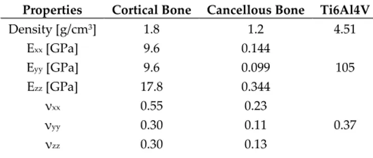
The cortical and cancellous bones exhibit a linear elastic orthotropic behavior, with the necessity of defining the Young’s modulus, Poisson’s ratio and Elastic tangential modulus in the three orthogonal directions (Table 1).
Table 1. Material properties and E module sources accordingly to the literature data (1,16,27,43).
Properties Cortical Bone Cancellous Bone Ti6Al4V
Density [g/cm3] 1.8 1.2 4.51 Exx [GPa] 9.6 0.144 105 Eyy [GPa] 9.6 0.099 Ezz [GPa] 17.8 0.344 νxx 0.55 0.23 0.37 νyy 0.30 0.11 νzz 0.30 0.13
Gxx [GPa] 3.10 0.053
38.32
Gyy [GPa] 3.51 0.063
Gzz [GPa] 3.51 0.045
The solid geometries were meshed with solid 4-node CTETRA4 tetrahedral elements while the contact zones were modelled with BSURFS element type. This kind of finite element defines a contact region which may act as a source or target. In order to obtain reliable stress values maintaining concurrently a reasonable calculation time, a convergence test was performed and an element size of 0.2 mm was chosen with an acceptable error below 5% compared to the 0.1 mm element size (Table 2). The final mesh configuration (Figure 11), in terms of number of nodes and elements, for the three different adopted geometries after the convergence test, are reported in Table 3.
Table 2. Results of the convergence test. Element size of 0.1 mm as taken as the reference.
Element Size [mm] Maximum Stress [MPa] Error [%]
0.1 276.69 −
0.2 268.56 2.94
0.3 194.06 29.86
0.4 181.93 34.25
0.5 176.84 36.09
Table 3. Dimension of the models with 0.2 mm element size.
AnyOne® External AnyOne® Internal AnyOne® OneStage
Elements 498,819 443,946 508,105
Nodes 105,804 96,583 108,369
(a) (b) (c)
Figure 11. Mesh for the three prosthetic devices: (a) AnyOne® External; (b) AnyOne® Internal; (c)
AnyOne® OneStage.
The hexahedral volumes of bone tissues were fixed at their lateral and lower faces and the bone-implant and bone-bone interfaces were modelled as bonded contacts in order to simulate the perfect osseointegration of the implant. The contact between the metal surfaces of the prostheses was modelled as frictional contact with a value of the frictional coefficient equals to 0.3.
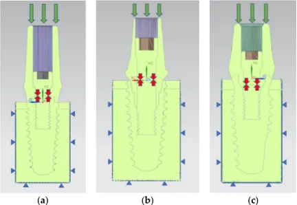
The prosthodontic component surfaces were loaded with a distributed compressive axial force of 800 N along the Y direction in order to simulate the effects of the maximum masticatory load [43] (Figure 12).
The internal screw was preloaded with a force of 875 N in order to simulate the tightening torque of 35 Ncm as suggested by the manufacturer. The value of the preload was estimated with the formula:
M = K D P
where M is the tightening torque (expressed in Nmm), K is a global coefficient that takes into account the friction coefficient on the thread (in this case equal to 0.2), D is the diameter of the screw (expressed in mm) and P is the axial preload to apply to the screw (expressed in N).
(a) (b) (c)
Figure 12. Loads and boundary condition on the prosthesis. The green arrows indicate the masticatory
load, the red arrows indicate the internal screw preload, while the blue triangles indicate the constraints: (a) AnyOne® External; (b) AnyOne® Internal; (c) AnyOne® OneStage.
5. Conclusions
Having clarified a whole series of biomechanical notions related to dental implants, and especially the influence of these on the peri-implant tissues, can lead to an improvement of the implant surfaces and even of their shape. Knowing the behavior of dental implants under masticatory load, and evaluating their effects with different angles, or prosthetic components, can lead to the realization of personalized rehabilitations for each patient and for every clinical need.
Author Contributions: For research articles with several authors, a short paragraph specifying their individual
contributions must be provided. The following statements should be used “conceptualization, G.R. and G.C.; methodology, G.R.; software, M.R., D.S. and F.C.; formal analysis, M.R., D.S. and F.C.; investigation, M.R., D.S. and F.C.; data curation, D.S.; writing—original draft preparation, D.S.; writing—review and editing, L.F.; visualization, M.C. and G.R.; supervision, L.F.; project administration, A.T., M.C. and G.R.
Funding: This research received no external funding.
Conflicts of Interest: The authors declare no conflict of interest.
References
1. Pihlstrom, B.L.; Michalowicz, B.S.; Johnson, N.W. Periodontal diseases. Lancet 2005, 366, 1809–1820. 2. Bjertness, E.; Hansen, B.F.; Berseth, G.; Gronnesby, J.K. Oral hygiene and periodontitis in young adults.
Lancet 1993, 342, 1170–1171.
3. Cervino, G.; Terranova, A.; Briguglio, F.; De Stefano, R.; Famà, F.; D'Amico, C.; Amoroso, G.; Marino, S.; Gorassini, F.; Mastroieni, R.; et al. Diabetes: Oral health related quality of life and oral alterations. BioMed
4. Cicciu, M.; Fiorillo, L.; Herford, A.S.; Crimi, S.; Bianchi, A.; D'Amico, C.; Laino, L.; Cervino, G. Bioactive Titanium Surfaces: Interactions of Eukaryotic and Prokaryotic Cells of Nano Devices Applied to Dental Practice. Biomedicines 2019, 7, 12.
5. Fiorillo, L. Chlorhexidine Gel Use in the Oral District: A Systematic Review. Gels 2019, 5, 31.
6. Germano, F.; Bramanti, E.; Arcuri, C.; Cecchetti, F.; Cicciù, M. Atomic force microscopy of bacteria from periodontal subgingival biofilm: Preliminary study results. Eur. J. Dent. 2013, 7, 152–158.
7. Cicciu, M.; Cervino, G.; Herford, A.S.; Fama, F.; Bramanti, E.; Fiorillo, L.; Lauritano, F.; Sambataro, S.; Troiano, G.; Laino, L. Facial Bone Reconstruction Using both Marine or Non-Marine Bone Substitutes: Evaluation of Current Outcomes in a Systematic Literature Review. Mar. Drugs 2018, 16, 27.
8. Cicciù, M. New Technological Opportunities and Innovative Biomedical Devices. Prosthesis 2019, 1, 1–2. 9. Cervino, G.; Fiorillo, L.; Arzukanyan, A.V.; Spagnuolo, G.; Cicciu, M. Dental Restorative Digital Workflow:
Digital Smile Design from Aesthetic to Function. Dent. J. 2019, 7, 30.
10. Esposito, M.; Hirsch, J.-M.; Lekholm, U.; Thomsen, P. Biological factors contributing to failures of osseointegrated oral implants, (II). Etiopathogenesis. Eur. J. Oral Sci. 1998, 106, 721–764.
11. Cicciu, M.; Bramanti, E.; Matacena, G.; Guglielmino, E.; Risitano, G. FEM evaluation of cemented-retained versus screw-retained dental implant single-tooth crown prosthesis. Int. J. Clin. Exp. Med. 2014, 7, 817–825. 12. Bramanti, E.; Cervino, G.; Lauritano, F.; Fiorillo, L.; D’Amico, C.; Sambataro, S.; Denaro, D.; Famà, F.; Ierardo, G.; Polimeni, A.; et al. FEM and Von Mises Analysis on Prosthetic Crowns Structural Elements: Evaluation of Different Applied Materials. Sci. World J. 2017, 2017, 1–7.
13. Cervino, G.; Fiorillo, L.; Iannello, G.; Santonocito, D.; Risitano, G.; Cicciù, M. Sandblasted and Acid Etched Titanium Dental Implant Surfaces Systematic Review and Confocal Microscopy Evaluation. Materials 2019,
12, 1763.
14. Fanuscu, M.I.; Caputo, A.A. Influence of attachment systems on load transfer of an implant-assisted maxillary overdenture. J. Prosthodont. 2004, 13, 214–220.
15. Dhatrak, P.; Shirsat, U.; Sumanth, S.; Deshmukh, V. Finite Element Analysis and Experimental Investigations on Stress Distribution of Dental Implants around Implant-Bone Interface. Mater. Today Proc.
2018, 5, 5641–5648.
16. Cicciù, M.; Cervino, G.; Milone, D.; Risitano, G. FEM analysis of dental implant-abutment interface overdenture components and parametric evaluation of Equator® and Locator® prosthodontics attachments. Materials 2019, 12, 592.
17. Topkaya, T.; Solmaz, M.Y. The effect of implant number and position on the stress behavior of mandibular implant retained overdentures: A three-dimensional finite element analysis. J. Biomech. 2015, 48, 2102–2109. 18. Rismanchian, M.; Bajoghli, F.; Eblaghian, G.; Reihany, A.; Yousefshahi, H. Stress Analysis of Ball and Locator Attachments and Bone in Overdenture Supported by Tissue Level and Bone Level Implants: A Three-dimensional Finite Element Analysis. J. Int. Oral Health 2016, 8, 952–957.
19. Arat Bilhan, S.; Baykasoglu, C.; Bilhan, H.; Kutay, O.; Mugan, A. Effect of attachment types and number of implants supporting mandibular overdentures on stress distribution: A computed tomography-based 3D finite element analysis. J. Biomech. 2015, 48, 130–137.
20. Wang, C.; Fu, G.; Deng, F. Difference of natural teeth and implant-supported restoration: A comparison of bone remodeling simulations. J. Dent. Sci. 2015, 10, 190–200.
21. Taheri, R.A.; Jarrahi, A.; Farnoosh, G.; Karimi, A. A comparative finite element simulation of stress in dental implant–bone interface using isotropic and orthotropic material models in three mastication cycles. J. Braz.
Soc. Mech. Sci. Eng. 2018, 40, 489.
22. Dhatrak, P.; Girme, V.; Shirsat, U.; Sumanth, S.; Deshmukh, V. Significance of Orthotropic Material Models to Predict Stress Around Bone-Implant Interface Using Numerical Simulation. BioNanoScience 2019, 9, 652– 659.
23. Van Staden, R.C.; Guan, H.; Loo, Y.C. Application of the finite element method in dental implant research.
Comput. Methods Biomech. Biomed. Eng. 2006, 9, 257–270.
24. Petrie, C.S.; Williams, J.L. Comparative evaluation of implant designs: Influence of diameter, length, and taper on strains in the alveolar crest. Clin. Oral Implant. Res. 2005, 16, 486–494.
25. Versluis, A.; Korioth, T.W.; Cardoso, A.C. Numerical analysis of a dental implant system preloaded with a washer. Int. J. Oral Maxillofac. Implant. 1999, 14, 337–341.
26. Jörn, D.; Kohorst, P.; Besdo, S.; Rücker, M.; Stiesch, M.; Borchers, L. Influence of lubricant on screw preload and stresses in a finite element model for a dental implant. J. Prosthet. Dent. 2014, 112, 340–348.
27. Cicciù, M.; Cervino, G.; Bramanti, E.; Lauritano, F.; Lo Gudice, G.; Scappaticci, L.; Rapparini, A.; Guglielmino, E.; Risitano, G. FEM Analysis of Mandibular Prosthetic Overdenture Supported by Dental Implants: Evaluation of Different Retention Methods. Computat. Math. Methods Med. 2015, 2015, 1–16. 28. Cervino, G.; Romeo, U.; Lauritano, F.; Bramanti, E.; Fiorillo, L.; D'Amico, C.; Milone, D.; Laino, L.;
Campolongo, F.; Rapisarda, S.; et al. Fem and Von Mises Analysis of OSSTEM ® Dental Implant Structural Components: Evaluation of Different Direction Dynamic Loads. Open Dent. J. 2018, 12, 219–229.
29. El-Anwar, M.I.; El-Zawahry, M.M. A three dimensional finite element study on dental implant design. J.
Genet. Eng. Biotechnol. 2011, 9, 77–82.
30. Ceruso, F.M.; Barnaba, P.; Mazzoleni, S.; Ottria, L.; Gargari, M.; Zuccon, A.; Bruno, G.; DI Fiore, A. Implant-abutment connections on single crowns: A systematic review. ORAL Implantol. 2017, 10, 349–353.
31. Saidin, S.; Abdul Kadir, M.R.; Sulaiman, E.; Abu Kasim, N.H. Effects of different implant–abutment connections on micromotion and stress distribution: Prediction of microgap formation. J. Dent. 2012, 40, 467–474.
32. Liu, Y.; Wang, J. Influences of microgap and micromotion of implant–abutment interface on marginal bone loss around implant neck. Arch. Oral Biol. 2017, 83, 153–160.
33. Chang, H.S.; Chen, Y.C.; Hsieh, Y.D.; Hsu, M.L. Stress distribution of two commercial dental implant systems: A three-dimensional finite element analysis. J. Dent. Sci. 2013, 8, 261–271.
34. Yamanishi, Y.; Yamaguchi, S.; Imazato, S.; Nakano, T.; Yatani, H. Influences of implant neck design and implant–abutment joint type on peri-implant bone stress and abutment micromovement: Three-dimensional finite element analysis. Dent. Mater. 2012, 28, 1126–1133.
35. Macedo, J.P.; Pereira, J.; Faria, J.; Pereira, C.A.; Alves, J.L.; Henriques, B.; Souza, J.C.M.; López-López, J. Finite element analysis of stress extent at peri-implant bone surrounding external hexagon or Morse taper implants. J. Mech. Behav. Biomed. Mater. 2017, 71, 441–447.
36. Kaleli, N.; Sarac, D.; Külünk, S.; Öztürk, Ö. Effect of different restorative crown and customized abutment materials on stress distribution in single implants and peripheral bone: A three-dimensional finite element analysis study. J. Prosthet. Dent. 2018, 119, 437–445.
37. Soliman, T.A.; Tamam, R.A.; Yousief, S.A.; El-Anwar, M.I. Assessment of stress distribution around implant fixture with three different crown materials. Tanta Dent. J. 2015, 12, 249–258.
38. Abuhussein, H.; Pagni, G.; Rebaudi, A.; Wang, H.-L. The effect of thread pattern upon implant osseointegration. Clin. Oral Implant. Res. 2010, 21, 129–136.
39. Merdji, A.; Bachir Bouiadjra, B.; Achour, T.; Serier, B.; Ould Chikh, B.; Feng, Z.O. Stress analysis in dental prosthesis. Computat. Mater. Sci. 2010, 49, 126–133.
40. Lee, C.-C.; Lin, S.-C.; Kang, M.-J.; Wu, S.-W.; Fu, P.-Y. Effects of implant threads on the contact area and stress distribution of marginal bone. J. Dent. Sci. 2010, 5, 156–165.
41. Borges Radaelli, M.T.; Idogava, H.T.; Spazzin, A.O.; Noritomi, P.Y.; Boscato, N. Parafunctional loading and occlusal device on stress distribution around implants: A 3D finite element analysis. J. Prosthet. Dent. 2018,
120, 565–572.
42. Frost, H.M. Bone’s mechanostat: A 2003 update. Anat. Rec. Part A Discov. Mol. Cell. Evolut. Biol. 2003, 275, 1081–1101.
43. Lauritano, F.; Runci, M.; Cervino, G.; Fiorillo, L.; Bramanti, E.; Cicciu, M. Three-dimensional evaluation of different prosthesis retention systems using finite element analysis and the Von Mises stress test. Minerva
Stomatol. 2016, 65, 353–367.
© 2019 by the authors. Licensee MDPI, Basel, Switzerland. This article is an open access article distributed under the terms and conditions of the Creative Commons Attribution (CC BY) license (http://creativecommons.org/licenses/by/4.0/).