SIMULTANEOUS EFFECT OF SPATIAL VARIABILITY OF GROUND MOTION DUE TO
SITE CONDITIONS AND SSI ON THE SEISMIC RESPONSE OF MULTI-SPAN VIADUCTSMaria Chiara Capatti Università Politecnica delle Marche
[email protected] Sandro Carbonari
Università Politecnica delle Marche [email protected]
Francesca Dezi
Università della Repubblica di San Marino [email protected]
Graziano Leoni Università di Camerino [email protected]
Michele Morici
Università Politecnica delle Marche [email protected]
Francesco Silvestri Università di Napoli Federico II
[email protected] Giuseppe Tropeano Università di Cagliari [email protected]
Abstract
This work focuses on the effects of the spatial variability of the seismic motion due to site effects on the seismic response of multi-span viaducts on pile foundations. A methodology is proposed to include the effects of both soil-structure interaction and non-synchronous seismic actions in the nonlinear response of bridges. Then, some results of nonlinear dynamic analyses performed on a multi-span bridge founded on soft soil are presented. The deposit is characterized by an inclined layout of the bedrock and the seismic input is represented by a set of suitably selected real accelerograms. Comparisons with results obtained considering synchronous seismic motions demonstrate the influence of site effects on the response of long bridges.
1. Introduction
Seismic design of bridges is traditionally performed assuming that piers are fixed at their base and subjected to the same input motion. It is evident from previous investigations (Carbonari et al., 2012) that Soil Structure Interaction (SSI) may sensibly affect the superstructure response. In fact, the beneficial or detrimental effects on each individual structural element can not be determine without performing more refined analyses that consider SSI. Furthermore previous researches (e.g. Lupoi et al., 2005) have proved that Spatial Variability of Ground Motion (SVGM) may be responsible for significant additional forces and deformations in structural members, especially for long bridges and other lifelines.
SVGM is usually attributed to three main factors: (i) the different arrival times of seismic waves at different locations due to the finite propagation velocity (wave-passage effect); (ii) the loss of coherency induced by multiple refractions and reflections of the incident seismic waves and their mutual interference;(iii) the different local soil conditions at each soil-structure contact points. In particular, the latter may produce significant variation of the ground motion amplitude and frequency content between different supports. To evaluate the contributions relevant to the seismic response of bridges, the above factors are often studied separately (e.g. Monti et al et al., 1996). However, SSI analysis is considered only in few works (e.g. Sextos et al., 2003). This note aims at investigate the effects of the non-synchronous ground motion induced by the variability of the local site amplification, on the seismic response of multi-span viaducts founded on piles, including the SSI effect.
2. General procedure
Following the substructure approach, the kinematic interaction analysis of the soil-foundation system is formulated in the frequency domain by adopting the model of Dezi et al. (2009), while the inertial interaction analysis is carried out in the time domain to account for the non-linear structural behaviour. The frequency-dependent behaviour of the soil-foundation system is included through the Lumped
Parameter Model (often called LPM) (Wolf, 1994). This approach is adopted to predict the seismic
response of a multi-span bridge founded on a soft soil deposit characterized by an inclined soil-bedrock interface. The reference input motion is defined by a set of selected real accelerograms satisfying specific constraints. In order to predict the stratigraphic amplification under each support both several independent 1D linear-equivalent site response analyses orand a single 2D non linear site response analysis can be performed. The bridge response is compared with the one obtained considering a horizontal bedrock.
2.1 Analitycal model
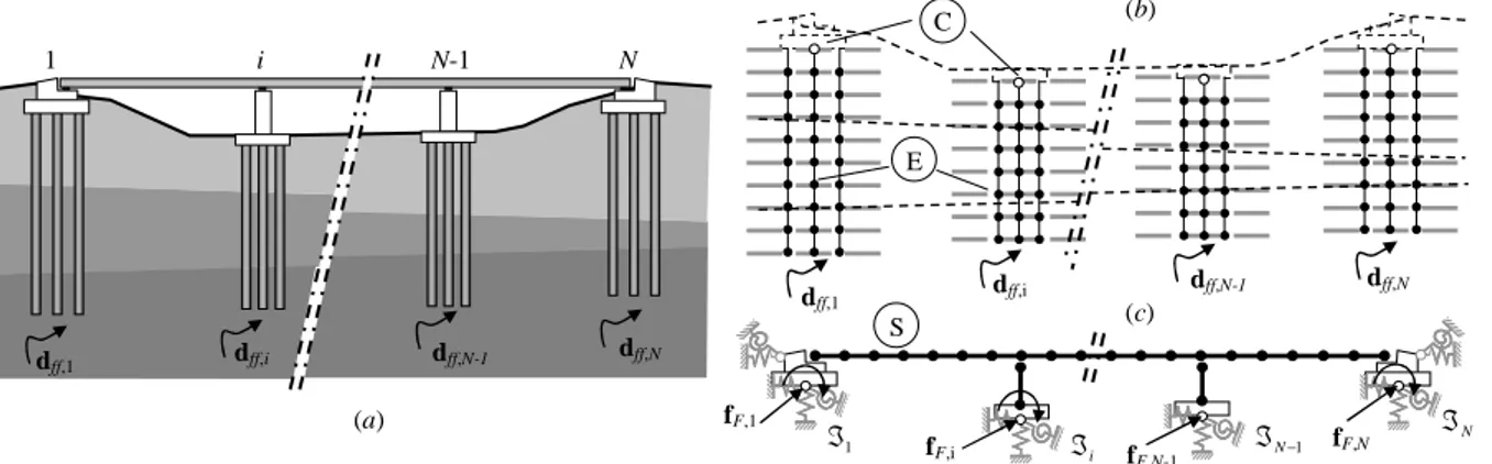
A generic bridge founded on N pile groups is considered (Figure 1a). Assuming that the non-linear behaviour of the soil-foundation system may be analysed through a linear equivalent approach, the SSI problem can be handled according to the substructure method, addressing the kinematic problem in the frequency domain. By neglecting the interaction between pile groups supporting different piers, the soil-foundation system relevant to each pier is analysed separately, using the finite element model proposed by Dezi et al. (2009) for the kinematic interaction of pile groups. For the i-th foundation, the following system of complex linear equations, governing the dynamic problem, may be assembled:
i E C i E C i F EE EC CE CC = f f d d Z Z Z Z , (1)
where Z is the dynamic stiffness matrix of the system, f is the vector of nodal forces and d is the vector of nodal displacements, which are suitably partitioned in order to highlight components of the embedded piles (E) and of the rigid cap (C) (Figure 1b). According to the adopted model, matrix Z accounts for soil-pile and pile-soil-pile interaction, while f collects the soil-pile interaction forces arising as a consequence of the seismic soil motion; they are defined as:
(
P,i 2 P,i P,i)
i T i i , F EE EC CE CC A Z M K A Z Z Z Z + − = ω i , ff i , P T i i E C A Z d f f = (2a, b) In Equation (2), KP,i and MP,i are the frequency-independent stiffness and mass matrices of piles, respectively, ZP,i is the complex frequency-dependent impedance matrix of the unbounded soil and dff,i is the free-field displacement vector within the deposit at the location of the i-th foundation. Being a the free-field displacement vector potentially different at each foundation, the approach allows to include non-synchronism effects on the bridge induced by the local soil conditions; these may be captured by performing either independent 1D S-wave propagation analyses under each support or a unique 2D or 3D seismic response analysis. Finally, Ai is a geometric matrix enforcing the kinematic constraint at the head of the i-th pile group. By simply manipulating system (1), the soil-foundation impedance matrixℑ
i and the foundation input motion, dC, necessary to perform inertial soil-structure interaction analysis, may be derived as follows:i F EC i F EE i F CE i F CC i , , 1 , , , , , ,
Z
Z
Z
Z
−
−=
ℑ
Ci i(
Ci CEFi EEFi C,i)
1 , , , , , 1 ,f
Z
Z
f
d
=
ℑ
−−
− (3a, b)The inertial interaction analysis is performed in the time domain to reproduce the non-linear behaviour of the superstructure. The frequency-dependent dynamic behaviour of the soil-foundation system is simulated by introducing suitable LPMs with frequency-independent parameters at the base of the superstructure (Wolf, 1994).
1 − ℑN N ℑ 1 ℑ i ℑ dff,1 E C 1 N S i N-1 dff,1 dff,i dff,N (a) dff,N-1 dff,i dff,N-1 dff,N fF,1 fF,i fF,N-1 fF,N (b) (c)
Figure 1. (a) Whole system; (b) model for soil-foundation system, (c) superstructure system
Impedances of LPMs
ℑ
~
i must approximate those of the soil-foundation system ℑi in the frequency range in which the input motion has the highest energy content and the fundamental periods of the structural vibration modes fall. The range 0÷10 Hz is usually considered for this purpose. From above, the dynamic stiffness matrix may be re-formulated for the i-th pile group:i LPM HH HC CH CC i LPM HH CC i LPM HH HC CH CC i F EE EC CE CC i , , 2 , , ω + ω − ≅ C C C C M 0 0 M K K K K Z Z Z Z (4) where subscript H refers to internal degrees of freedom of the LPM. K, M and C are positive definite matrices with frequency-independent components. The Foundation Input Motion (hereafter called FIM) is applied at the base of the superstructure by considering forces fF,i acting at the caps of pile groups for the i-th group, properly transformed in the time domain. The inertial interaction problem of the discrete system (Figure 1c) may be formulated as:
( )
= + + + + + F NL F S LPM F S LPM FF FS SF SS F S LPM FF SS f 0 u u f u u K 0 0 0 u u C C C C C u u M M 0 0 M & & & & & & & , (5)where M is the mass matrix of the system, obtained by assembling structural masses of the deck (MSS), piers and foundation caps (MFF) and masses of LPMs (MLPM): C is the damping matrix resulting from the contributions of LPMs (CLPM) and of the structure. KLPM is the stiffness matrix obtained by considering contributions of LMPs and fNL is the vector of the non-linear restoring forces of the system. Finally, fF is the vector collecting forces fF,i evaluated considering different FIMs at each pier. 3. Case study
The procedure depicted above is adopted to investigate effects of spatial variation of ground motion induced by site effects on the seismic response of the 10-span viaduct with continuous steel-concrete composite deck showed in Figure 2a, b. Foundations are constituted by groups of bored r.c. piles with 1.2 m diameter and 30 m long (Figure 2c). The 15 m high circular piers of diameter 2.4 m are designed to withstand the displacement demand (due to the bidirectional action) with an expected ductility µ ≈ 2. Further details of the bridge design can be found in Carbonari et al. (2012).
For the present application, a soft soil deposit overlying a seismic bedrock is considered; in the longitudinal direction of the bridge, the soil–bedrock interface plane is either horizontal (HB configuration) or sloped 15° (IB configuration), so that the bedrock depth at the middle bridge support is equal to 97 m, for both the configurations (Figure 2a). The deposit is constituted by normally consolidated clays with properties reported in Figure 2d; the variability with depth of the small-strain shear modulus (G0) is defined according to the empirical formulas of d’Onofrio and Silvestri (2001).
The shear wave velocity profile (Figure 2e) corresponds to an equivalent Vs,30 (149 m/s) falling in the range defined by EN1998-1 for soil class D. The bedrock has shear wave velocity Vs,b = 1000 m/s and density ρb = 2.0 Mg/m
3
3.1 Non Synchronous Seismic Input due to Site Effects
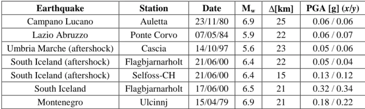
The reference input motion is constituted by a set of seven real records defined at outcropping bedrock and selected so that their mean pseudo-acceleration elastic response spectrum (normalised with respect to PGA) matches the relevant spectrum suggested by EN1998-1 for soil type A. The input motions, reported in Table 1, are characterized by 2 orthogonal horizontal components digitized by free-field stations located on rock outcrop, with magnitude, Mw, ranging between 5 and 7, and epicentral
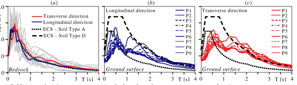
distances, ∆, less than 30 km. The signals are scaled in order to obtain the design hazard level; the mean scale factor adopted is about 4.3. Figure 3a shows the mean elastic acceleration response spectra of longitudinal (x) and transverse (y) components of the selected records, compared with the code reference spectrum. Spectra relevant to all records are reported with light grey lines to provide a pictorial view of the input variability.
Independent 1D site response analyses are performed in the x and y directions to evaluate the non-synchronous seismic motion at the ground surface due to different stratigraphic amplification. A linear equivalent model is used for the soil, calibrating shear modulus and damping consistently with the maximum strain level attained during the shaking on the basis of the curves suggested by Vucetic and Dobry (1991) for similar kind of soil, Figure 3b and c shows the mean elastic response spectra obtained at the ground surface at the location of each pier, compared with the reference spectrum of the code for soil type D.
10 m (a) (b) (c) 2 m 1.8 m 7.4 m 6 m 12 m 2.9 m 13.2 m 13.2 m x y ρl = 1.56% ρw = 0.76% 60 P1 P2 P3 P4 P5 P6 P7 P8 P9 75 75 75 75 75 75 75 75 60 x y IB – Inclined Bedrock 15° 97 0 Vs [m/s] 250 -2 -10 -20 -30 z [m] -40 g.l. Mass density PI Undrained resistance Friction angle 1.83 20 [Mg/m3] [%] 28 [°] 0.35 · σ’v0 (z) [kPa] CS CS (d) (e) HB – Horizontal Bedrock
Figure 2. (a) Lateral view of the viaduct; (b) pie; (c) foundation and pier cross section; (d) soil properties and (e) Vs profile
Table 1. Selected earthquake, including station name, magnitude and epicentral distance
Earthquake Station Date Mw ∆[km] PGA [g] (x/y)
Campano Lucano Auletta 23/11/80 6.9 25 0.06 / 0.06
Lazio Abruzzo Ponte Corvo 07/05/84 5.9 22 0.06 / 0.07
Umbria Marche (aftershock) Cascia 14/10/97 5.6 23 0.05 / 0.06 South Iceland (aftershock) Flagbjarnarholt 21/06/00 6.4 22 0.05 / 0.04 South Iceland (aftershock) Selfoss-CH 21/06/00 6.4 15 0.13 / 0.12 South Iceland Flagbjarnarholt 17/06/00 6.5 21 0.32 / 0.34
Figure 3. Mean acceleration response spectra of selected accelerograms (a), mean acceleration response spectra at ground surface of each support for the IB configuration: longitudinal (b) and transverse (c) directions
Spectral amplifications are evident at all piers for periods greater than 1 s, and result overall consistent with those quantified by the code; moving from P1 to P9, the period corresponding to the highest amplification increases, as a consequence of the increasing bedrock depth. It is worth noting that results obtained for P5 are representative of the HB configuration of the soil deposit.
3.2 Kinematic and Inertial interaction
Analyses of the soil-foundation systems are performed with the numerical model described above; the piles, modelled with 1 m long beam elements, have density ρp = 2.5 Mg/m³ and Young’s modulus
Ep ≈ 23.5 GP. Figure 4 shows the translational, rotational and coupled roto-translational components of the impedance matrix for the piers foundation (solid lines).
Non-linear analyses of inertial interaction are carried out in time domain, developing a 3D finite element model of the bridge. Linear elastic beam elements are used for the deck, while fiber elements are adopted for piers to capture their non-linear behaviour under bidirectional excitation. Figure 4 shows the impedances of the LPMs calibrated to approximate the behaviour of the soil-foundation system in the range 0÷10 Hz (dashed lines).
The foundation input motion is represented by generalised forces applied at the level of pile caps. For IB configuration, the seismic actions are different at each pier and account for the site-induced non-synchronism. Conversely, the FIM relevant to HB configuration is synchronous at all supports and is the same as that obtained for pier P5.
ℑx Im Re 0 10 f [Hz] 20 Re Im ℑry Re Im ℑx-ry LPM Foundation impedance 0 ·106 [kN/m] ·107 [kNm/rad] ·105 [kN/rad] 20 5 x y x z 0 5 10 f [Hz] 20 0 5 10 f [Hz] 20 ℑy ℑrx ℑy-rx -10 10 0 50 75 -25 25 100 15 20 25 10 5 30 0
Figure 4. Components of the soil-foundation system impedance matrix
P1 P2 P3 P4 P5 P6 P7 P8 P9 0 1 2 3 µ Design Ductility 5 Ultimate Ductility HB IB 0 D is p l. [ m ] 0.8
Longitudinal direction Transverse direction
Min Mean Max Design displ. Yielding displ. P1 P2 P3 P4 P5 P6 P7 P8 P9 P1 P2 P3 P4 P5 P6 P7 P8 P9 (a) (b) (c) HB IB
Figure 5. Deck displacements in (a) longitudinal (b) transverse direction; (c) ductility demand Sa /P G A 4.0 0 1.0 2.0
EC8 – Soil Type A Transverse direction Longitudinal direction
Bedrock
EC8 – Soil Type D
Ground surface P1 P2 P3 P4 P5 P6 P7 P8 P9 P1 P2 P3 P4 P5 P6 P7 P8 P9 Ground surface Transverse direction 0 1 2 3 T [s] 4 (a) 0 1 2 3 T [s] 4 0 1 2 3 T [s] 4 (b) (c) Longitudinal direction
3.3 Main results
The effects of the spatial variability of ground motion due to site effects on the non-linear seismic response of the case study can be assessed comparing the results obtained for IB and HB configurations. Some significant results will be shown in terms of mean values obtained from the non-linear dynamic analyses performed with the whole set of accelerograms.
Figure 5a and b shows the peak values of the relative displacements of the deck with respect to the foundation, in the longitudinal and transverse directions, respectively. The spatial variability of ground motion (IB configuration) affects displacements in the longitudinal direction where the coupling effect exerted by the rigid deck is more pronounced, being the displacements at P6-P7-P8-P9 about one half those obtained for HB configuration. In the transverse direction, very slight differences can be observed between displacements resulting from HB and IB configurations.
Figure 5c compares the displacement ductility demand of each pier, evaluated with reference to the combined longitudinal and transverse displacements resulting from HB and IB configurations, by suitably accounting for the effects of the foundation rigid rotation. The ductility demand is almost coincident with the design one (dotted line) and is far from the ultimate ductility (dashed line). Effects of the spatial variability of ground motion are evident at the edge piers and particularly at piers with thicker soil deposits (P7-P8-P9) where a significant decrease of the ductility demand is observed, consistently with the reduction of the longitudinal and transverse displacements.
4. Conclusion
A numerical methodology to include effects of non-synchronous seismic motion induced by local stratigraphic conditions in the SSI analysis of multi-span viaducts on pile foundations is presented and applied to study a multi-span bridge founded on a soft soil deposit overlying an inclined bedrock. The reference input motions is represented by a set of suitably selected real accelerograms, and spatial variability of ground motion due to site effects is evaluated with multiple 1D site response analyses. Comparing the results with those obtained by considering an horizontal bedrock (i.e. synchronous motion) proves that the specific soil conditions at each bridge support play a key role in the definition of the seismic action and that considering in the analyses the SVGM due to site effects is crucial for a reliable prediction of the structural response. Future developments of the research will focus on the role of the buried bedrock geometry in the modification of the resulting bridge motion, by means of 2D non linear seismic response analyses.
References
Carbonari S, Morici M, Dezi F, Nuti C, Silvestri F, Tropeano G., Vanzi I. Seismic response of viaducts accounting for soil-structure interaction. 15 WCEE 2012, Lisbon, Portugal, Sept. 2012, paper n.4150.
Dezi, F, Carbonari S, Leoni G. A model for the 3D kinematic interaction analysis of pile groups in layered soils. Earthquake Engng Struct. Dyn., 2009; 38 (11): 1281–1305.
d’Onofrio A, Silvestri F. Influence of micro-structure on small-strain stiffness and damping of fine grained soils and effects on local site response. IV Int. Conf. on 'Recent Advances in Geotech. Earthquake Engng and Soil Dynamics', 2001, S. Diego, CA. Paper 1.19.
Lupoi A, Franchin P, Monti G, Pinto PE. Seismic design of bridges accounting for spatial variability of ground motion. Earthq. Eng. & Struct. Dyn., 2005; 34: 327-348.
Monti G, Nuti C, Pinto PE. Nonlinear response of bridges under multisupport excitation. ASCE Jnl Struct. Eng. 1996; 122 (10):1147-1159.
Sextos AG, Pitilakis KD, Kappos AJ. Inelastic dynamic analysis of RC bridges accounting for spatial variability of ground motion, site effects and soil-structure interaction phenomena. Part 2: Parametric study. Earthquake Engng Struct. Dyn., 2003; 32 (4): 629-52.
Vucetic M, Dobry R. Effect of soil plasticity on cyclic response. Journ. of Geot. Eng. ASCE, 1991; 117 (1), 89-107. Wolf JP. Foundation Vibration Analysis Using Simple Physical Models, Prentice-Hall: Englewood Cliffs N.J., 1994.