University of Pisa
Engineering Ph.D. School "Leonardo da Vinci”
Ph.D. course in Chemical and Material Engineering
XXIV cycle
Realization and characterization of
bioactive composite materials for
locomotor tissue regeneration
ING-IND34
Tutor
Eng. Giovanni Vozzi
Prof. Giuliano Cerulli
PhD student
Francesca Montemurro
Abstract
Tissue Enginnering emerges as a potential and alternative therapeutic process to treat severely injured patients with minimally invasive techniques. Cartilage and bone injuries occur due to several reasons and they compromise quality of life. This thesis was focused on development of biomaterials that could mimic cartilage and bone tissue, using only natural substances, gelatin and/or colla-gen, crosslinked with genipin (GP) and hydroxyapatite (HA) . These materials are cheap and easy to handle, and in particular collagen, represents a chemo-attractor factor, that may help cellular colonization. First of all genipin reaction was studied to establish reaction rate constant and crosslinking degree as func-tion of genipin concetrafunc-tions. The optimal genipin concentrafunc-tion was decided primarly assuring that it was not cytotoxic, meseauring its release in acqueous enviroment. Then elastic moduli of scaffolds prepared with different GP con-centrations, different protocols and different HA concentrations were measured taking into account that scaffolds had to present mechanical properties suited to the implant site. Roughness surface of scaffolds, was also investigated with SEM, to ensure an optimal integration with implant site and to verify the presence of a right porosity to allow its cell colonisation. Bone scaffolds were arranged to reproduce a HA gradient, an important bone feature, and their anisotropy was valueted. Biocompatibility tests, in vitro tests, for cartilage and bone
als were performed using primary and immortalised cells. Finally preliminary in vivo tests using small animal models, rats with a femur lesion, were performed for cartilage and bone substitute, selected on the basis of their mechanical prop-erties. The aim was to follow bone and cartilage regeneration, after injection of biomaterials, and to compare it with the physiological regeneration.
Acknowledgements
Ed ora la parte più difficile per me....Siccome ormai inizio ad avere una “certa età”, e le persone da ringraziare sono tante, mi scuso da subito se dimentico qualcuno. Inizio ringraziando i tutor: Giovanni Vozzi per aver creduto in me sin dall’inizio e per avermi voluto nel “regno” del Centro Piaggio, e soprattutto per avermi introdotto e svelato il mondo della Bioingegneria; il Professor Cerulli per avere sostenuto e reso possibile tutto questo lavoro di ricerca attraverso la Nicola’s Foundation e la Let People Move; il co-tutor Dott. Claudio Domenici, che mi ha ospitato nel fondamentale laboratorio della Fisiologia Clinica del CNR e che ha diviso con me i suoi buoni pasto della mensa (anche se il risotto con gli spinaci e un pò di sugo sopra è la negazione della cucina mediterranea!!!). Ringrazio la Prof. Arti Ahluwalia per i suoi continui stimoli e preziosi consigli, poi tutto l’MCB group (Ma Che Bel gruppo!!!): naturalmente inizio con Tita (per gli amici Annalisa) spalla lavorativa ed extra-lavorativa, che mi ha support-ato e sopportsupport-ato, poi il compagno di avventura di PhD Carmelo (l’altra metà del neurone...), il Vozzino (Federico) amico di lunga data, che mi ha svelato tutti i segreti del mondo cellulare, Serena che riesce sempre a risollevare le giornate degli altri (non volendo) con i suoi piccoli inghippi....Continuo con l’Elbano (Daniele) e le sue perle di saggezza, Tommy “il diplomatico”, Giorgi(o) ed i suoi fegatelli, Gianni e il silicone, Nadia e il suo tentativo di ordinare il lab, l’italiano Yudano, la
dott.ssa Vinci la donna più impegnata del mondo. Ringrazio la Dott.ssa Monica Mattioli Belmonte e Concetta per l’ospitalità riservatami in quel di Ancona e per il fondamentale apporto nella parte biologica di questo lavoro. Ugualmente im-portanti sono stati gli amici (Dina in primis) e la valvola di sfogo extralavorativa, il calcetto con tutte le ragazze ed i mister che si sono succeduti nel tempo. Infine, naturalmente ringrazio tutta la mia famiglia per avermi sostenuto in tutto e per tutto. Grazie a tutti.
Francesca
Contents
Abstract i
Acknowledgements iii
Table of Contents v
List of Abbreviations xi
List of Figures xiii
List of Tables xix
1 Bone and cartilage 1
1.1 Cartilage . . . 2
1.1.1 Cartilage defects . . . 2
1.1.2 Tissue engineering . . . 4
1.2 Bone . . . 5
1.2.1 Bone repair . . . 5
1.2.2 Bone tissue engineering . . . 6
1.3 Material selection . . . 7 v
1.3.1 Gelatin . . . 7 1.3.2 Collagen . . . 9 1.3.3 Genipin . . . 10 1.3.4 Hydroxyapatite . . . 13 2 Genipin reaction 15 2.1 Introduction . . . 15 2.1.1 Mechanism reaction . . . 15
2.1.2 Rate and order reaction . . . 17
2.1.3 Diffusion coefficient . . . 19
2.2 Experimental section . . . 21
2.2.1 Sample preparation to evaluate reaction rate constant . . . 21
2.2.2 Image elaboration . . . 22
2.2.3 Diffusion device . . . 22
2.2.4 Fluorescamine assay . . . 23
2.3 Results . . . 24
2.3.1 Reaction rate constant . . . 24
2.3.2 Static and dynamic diffusion coefficient . . . 29
2.3.3 Fluorescamine assay . . . 34 2.4 Conclusions . . . 35 3 Scaffold characterisation 37 3.1 Introduction . . . 37 3.1.1 Young’s modulus . . . 38 3.1.2 Stress-strain curve . . . 39 3.2 Experimental section . . . 40 3.2.1 Scaffold preparation . . . 40
Collagen matrix constructs . . . 40
Agar matrix constructs . . . 41
Gelatin matrix constructs . . . 41
3.2.2 Collagen release . . . 43
3.2.3 Genipin Release . . . 43
3.2.4 Swelling tensile stress-strain and creep tests . . . 44
3.2.5 Dynamic loading test . . . 44 vi
3.2.6 Compression stress-strain . . . 45
3.2.7 Genipin release . . . 46
3.2.8 Load unload cyclic tests . . . 46
3.2.9 SEM and SEM-EDX . . . 46
3.3 Results . . . 47
3.3.1 Collagen release . . . 47
Cartilage scaffolds and bone scaffolds . . . 47
3.3.2 Genipin release . . . 47 Cartilage scaffolds . . . 47 Bone scaffolds . . . 47 3.3.3 Stress-strain test . . . 48 Cartilage scaffolds . . . 48 Bone scaffolds . . . 50
Bone scaffolds with lower GP concentration and higher HA content . . . 50
48h after preparation . . . 51
10 days after preparation . . . 54
3.3.4 Swelling test . . . 55 Cartilage scaffolds . . . 55 Bone scaffolds . . . 56 3.3.5 Creep test . . . 57 Cartilage scaffolds . . . 57 Bone scaffolds . . . 58
3.3.6 Dynamic loading test . . . 59
Cartilage scaffolds . . . 59 3.3.7 SEM micrographies . . . 60 Cartilage scaffolds . . . 60 Bone scaffolds . . . 62 3.3.8 SEM-EDX . . . 62 3.4 Conclusions . . . 63 4 Graded Scaffolds 67 4.1 Introduction . . . 67 vii
4.1.1 Gradients in natural structures . . . 67
4.1.2 pH during fracture healing . . . 68
4.2 Experimental section . . . 69
4.2.1 Homogeneous and discrete graded samples preparation . . . 69
4.2.2 Buffer solution preparation . . . 70
4.2.3 Load-unload cyclic tests . . . 70
4.3 Results . . . 70
4.3.1 Cyclic compression tests on discrete gradient samples . . . 70
48h after preparation . . . 71
10 days after preparation . . . 74
4.3.2 Elastic modulus at different pH . . . 75
48h casting . . . 75 10 days casting . . . 75 4.4 Conclusions . . . 76 5 In vitro tests 77 5.1 Introduction . . . 77 5.1.1 Genipin biocompability . . . 77 5.2 Experimental section . . . 78 5.2.1 Scaffold sterilization . . . 78
5.2.2 Cell culture and seeding . . . 79
Cartilage scaffolds . . . 79
Bone scaffolds . . . 79
5.2.3 Alamar blue assay . . . 79
5.2.4 DAPI staining . . . 80
5.2.5 SEM and SEM-EDX . . . 80
5.3 Results . . . 81 5.3.1 Cell viability . . . 81 5.3.2 SEM micrographies . . . 82 5.3.3 SEM-EDX micrographies . . . 85 5.4 Conclusions . . . 86 viii
6 In vivo tests 87 6.1 Introduction . . . 87 6.2 Experimental section . . . 88 6.2.1 Implantation procedure . . . 88 6.2.2 Micro CT analysis . . . 89 6.2.3 Histology . . . 89 6.3 Results . . . 90 6.3.1 In vivo µCT . . . 90 6.3.2 Ex vivo µCT . . . 91 6.3.3 Histology . . . 92 6.4 Conclusions . . . 96 Conclusions 97 Author Publications 99 Bibliography 111 ix
List of Abbreviations
A Agar
ACC Agar and crosslinked collagen AHA agar hydroxyapatite
ANCC Agar and not crosslinked collagen ANCCHA agar+not crosslinked collagen+HA BSA Bovine serum albumin
Ca-P calcium phosphate CC Collagen Constructs CPD critical point drying DAPI 4’,6-diamino-2-phenyldione
DMEM Dulbecco’s Modified Eagle’s Medium DMSO Dimethyl sulfoxide
ECM extra-cellular matrix
EDC 1-ethyl-3-(3-dimethyl aminopropyl)-carbo-diimide G gelatin and genipin
GAG glycosaminoglyan
GHA gelatin+HA crosslinked with genipin
GNCC gelatin and genipin with not crosslinked collagen GNCCHA gelatin+not crosslinked collagen+HA
GPCC gelatin and genipin with pre crosslinked collagen HA hydroxyapatite
NHS N-hydroxysuccinimide PBS phosphate buffered saline PEG poly(ethylene glycol) PEO polyethylenoxide PGA poly(glycolic acid) PLA poly(D,L-lactic acid) PLGA poly(lactic-co-glycolic acid) PO propylene oxide
SEM Scanning electron microscopy
SEM-EDX Scanning electron microscopy-energy dispersive xray micro-analysis TCP tricalcium phosphate
TE Tissue Engineering
List of Figures
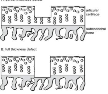
1.1.1 A partial thickness focal defect in articular cartilage (A) and a full
thickness defect involving the subchondral bone (B). . . 3
1.3.1 Gelatin structural unit. . . 8
1.3.2 Principal types of collagen . . . 9
1.3.3 Schematic diagram of Type I collagen fibril structure. . . 11
1.3.4 The structure of collagen, from the α chains to the fiber. . . 12
1.3.5 The chemical structures of genipin and geniposide. . . 12
2.1.1 Crosslinking structures presumed for (a) a fresh gelatin hydrogel (a gelatin hydrogel without crosslinking), (b) a GP-crosslinked gelatin hydrogel, (c) an EDC/NHS-crosslinked gelatin hydrogel. . . 16
2.1.2 The fastest crosslinking reaction involving genipin. . . 17
2.1.3 (a) Concentration-time graph and (b) rate-concentration graph to evaluate order reaction. . . 19
2.2.1 Gelatin and gelatin/collagen samples crosslinked with genipin at different concentrations. . . 21
2.2.2 Diffusion device. . . 22
2.2.3 Divider composition. . . 23 xiii
LIST OF FIGURES LIST OF FIGURES 2.3.1 Blue intensity against time as expression of rate reaction, for gelatin
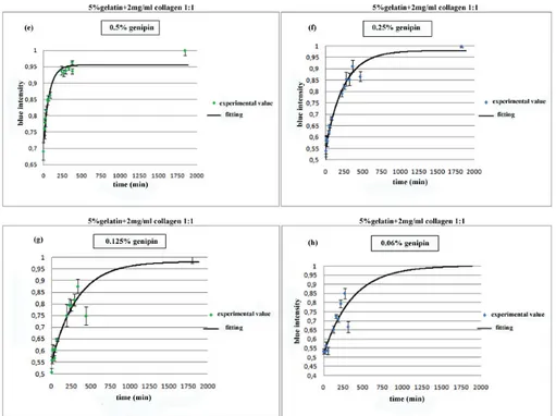
collagen samples at different genipin concentration (a)2.5%, (b)2%, (c)1.5%, (d)1% w/w. . . 26 2.3.2 Blue intensity against time as expression of rate reaction, for gelatin
collagen samples at lower genipin concentration (e)0.5%, (f)0.25%, (g)0.125%, (h)0.06%w/w. . . 28 2.3.3 Blue intensity against time as expression of rate reaction, for 5%
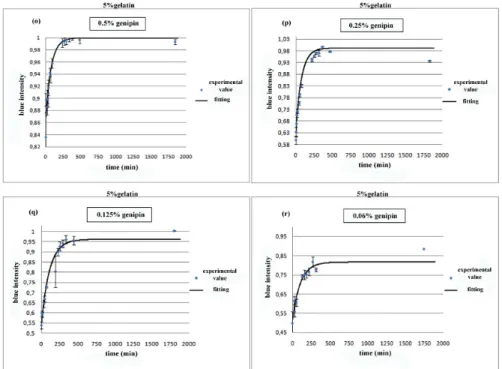
gelatin samples at different genipin concentration (i)2.5%, (l)2%, (m)1.5%, (n)1% w/w. . . 29 2.3.4 Blue intensity against time as expression of rate reaction, for 5%
gelatin samples at different genipin concentration (o)0.5%, (p)0.25%, (q)0.125%, (r)0.06% w/w. . . 30 2.3.5 Genipin concentrations in diffusion chambers through 1% w/v agarose
membrane versus time and fitting curve; (a) 0.5% w/v genipin con-centration and (b) 0.25% w/v genipin concon-centration in the bigger chamber. . . 33 2.3.6 Genipin concentrations in diffusion chambers through 5% w/v gelatin
membrane versus time and fitting curve; (a) 0.5% w/v genipin con-centration and (b) 0.25% w/v genipin concon-centration in the bigger chamber. . . 34 2.3.7 Free amino groups content at different GP concentrations. . . 34 3.1.1 Stress-strain curve: stress σ� as function of strain ε. 1) true elastic
limit; 2) proportionality limit; 3) elastic limit; 4) offset yield strength. 39 3.3.1 Genipin release from cartilage subsitutes after 8 days. . . 47 3.3.2 GP release from bone scaffolds (0.5% w/w GP) after one week,
prepared with two different protocols. . . 48 3.3.3 (a) Stress-strain curves of agar matrix samples; (b) Stress-strain
curves of gelatin matrix samples. . . 49 3.3.4 Young’s moduli of agar and gelatin samples with 2.5% GP content. 49 3.3.5 Young’s moduli of gelatin/collagen samples with lower GP content. 50 3.3.6 (a) Stress-strain curve for bone sustitutes based on gelatin matrix
and (b) on agar matrix. . . 51 xiv
LIST OF FIGURES LIST OF FIGURES 3.3.7 Young’s moduli for samples after 48h casting, prepared with two
different protocols. . . 52 3.3.8 Young’s moduli for samples after 48h casting, prepared with the
second protocol. . . 53 3.3.9 Young’s modulus for samples after 48h casting calculated in the
normal and tangential direction. . . 53 3.3.10Young’s moduli for all HA concentrations tested after 48h casting 53 3.3.11 Young’s moduli for samples after 10 days casting, prepared with
two different protocols. . . 54 3.3.12 Young’s modulus for samples after 10 days casting calculated in
the normal and tangential direction. . . 54 3.3.13 Young’s moduli for samples after 10 days casting, prepared with
the second protocol. . . 55 3.3.14Young’s moduli of all HA concentration after 10 days of casting.
Values on Y axis are in logarithmic form. . . 55 3.3.15Gelatin+collagen+0.5%GP+60% HA sample swelling. . . 56 3.3.16Creep experimental data with fitting curve for CC(crosslinked
col-lagen), A(agar), ANCC(Agar+not crosslinked colcol-lagen), ACC(agar+crosslinked collagen), G(gelatin+GP), GNCC(gelatin+not-crosslinked collagen+GP), GPCC(gelatin+pre-crosslinked collagen+GP). . . 58 3.3.17Creep test with fitting curve for ANCCHA (agar+not-crosslinked
collagen+43.7%HA) and GNCCHA (gelatin+not-crosslinked col-lagen+2.5%GP+43.7%HA). . . 59 3.3.18Dynamic loading curve of (CC) Cross-linked collagen; (A) Agar;
(ANCC) Agar and not cross-linked collagen; (ACC) Agar and cross-linked collagen. . . 61 3.3.20 SEM micrographs of (a) GNCCHA (gelatin+not-crosslinked
col-lagen+2.5%GP+43.7%HA) at 35x magnification; (b) at 250x mag-nification and (c) at 1000x magmag-nification. . . 62
3.3.21SEM-EDX for bone sustitute gelatin+not-crosslinked collagen+2.5%GP+43.7%HA. 63 xv
LIST OF FIGURES LIST OF FIGURES 3.3.19SEM micrographs of (a) Gelatin (1000x magnification); (b) Genipin
and not cross-linked collagen (35x magnification); (c) Genipin and not cross-linked collagen (250x magnification); (d) Genipin and not cross-linked collagen (500x magnification); (e) Genipin and
not cross-linked collagen (1000x magnification). . . 65
4.1.1 pH variation during healing fracture. . . 69
4.3.1 Load application to discrete scaffolds. . . 71
4.3.3 Elastic modulus of multilayer scaffold after one compression cycle. 71 4.3.2 Elastic moduli (after 48 hours from preparation) of discrete gradi-ent scaffolds made by homogeneous samples. . . 72
4.3.4 Voigt and Reuss models. . . 73
4.3.5 Elastic moduli (after 10 days from preparation) of discrete gradient scaffolds made by homogeneous samples. . . 74
4.3.6 Elastic moduli trend at different pH for 48h casting sample. . . 75
4.3.7 Elastic moduli trend at different pH for 10 days casting sample. . . 76
5.3.1 Fibroblasts viability seeded on cartilage scaffolds respect to control . 81 5.3.2 Dapi staining for (a) fibroblasts on cartilage scaffolds and (b) on gelatin/collagen coating (control) at third day. . . 82
5.3.3 SEM of 22.5% HA samples at 500X and 1000X magnification. . . 83
5.3.4 SEM of 47.5% HA samples at 500X and 2000X magnification. . . 83
5.3.5 SEM of 60% HA samples at 500X and 2000X magnification. . . 84
5.3.6 SEM of 70% HA samples at 250X and 1000X magnification. . . 84
5.3.7 SEM of 80% HA samples at 500X and 1000X magnification. . . 84
5.3.8 SEM of 90% HA samples at 1000X magnification. . . 85
5.3.9 SEM-EDX of (a) 60% HA and (b) 70% HA samples showing Ca (red) and P (green) distribution. . . 85
5.3.10 SEM-EDX of 90% HA sample showing Ca (red) and P (green) inclusions and distribution. . . 86
6.2.1 Cartilage biomaterial injenction in rat knee. . . 88
6.2.2 Bone biomaterials implantation in left rat femur. . . 89
6.3.1 Bone volume of left and right legs after 45 days and 100 days. . . . 90 xvi
LIST OF FIGURES LIST OF FIGURES 6.3.2 Axial plane of (a) right and (b) left femur of rats with 80% HA
biomaterial. . . 92 6.3.4 Ex vivo high resolution image of cartilage damage after 100 days
from biomaterial implant. . . 92 6.3.3 Sagittal plane of (a) right and (b) left femur of rats with 80% HA
biomaterial. . . 93 6.3.5 Macroscopic identification of diaphysis lesion. . . 93 6.3.6 Microscopic images: (a) medullary spaces and (b) blood vessels and
new osteocytes in cortical bone. . . 94 6.3.7 (a) Periosteal (left femur) and (b) endosteal (right femur) Howship
lacunae. . . 94 6.3.8 (a) Reduced cortical thickness, medullary spaces; (b) irregular
en-dosteal profile. . . 94 6.3.9 Macroscopic identification of epiphysis femoral lesion. . . 95 6.3.10Cartilage damage, and cancellous bone replaced with fibrous tissue. 95
LIST OF FIGURES LIST OF FIGURES
List of Tables
2.1 Coefficients from Matlab elaboration for gelatin collagen and high genipin concentration. . . 26 2.2 Coefficients from Matlab elaboration for gelatin collagen and low
genipin concentration. . . 27 2.3 Coefficients from Matlab elaboration for 5% gelatin and high genipin
concentration . . . 27 2.4 Coefficients from Matlab elaboration for 5% gelatin and low genipin
concentration . . . 28 2.5 Coefficients from Matlab elaboration with its confidence interval
for genipin diffusion through agarose. . . 33 2.6 Coefficients from Matlab elaboration with its confidence interval
for genipin diffusion through gelatin. . . 33 3.1 Young’s modulus of bone substitute based on agar and on gelatin
matrix. . . 52 3.2 Swelling results for CC(crosslinked collagen), A(agar), ANCC(Agar+not crosslinked collagen), ACC(agar+crosslinked collagen), G(gelatin+GP), GNCC(gelatin+not crosslinked collagen+GP), GPCC(gelatin+pre crosslinked collagen+GP). . . 56
LIST OF TABLES LIST OF TABLES 3.3 Calculated coefficients for cartilage creep test. . . 57 3.4 Calculated coefficients for bone subsittutes creep test. . . 60 4.1 Experimental and calculated elastic moduli for 30%-50% HA
sam-ple after 48h casting. . . 73 4.2 Experimental and calculated elastic moduli for multilayer HA
sam-ple after 48h casting. . . 74 4.3 Experimental and calculated elastic moduli for 30%-50% HA
sam-ple after 10 days casting. . . 75 6.1 Bone volume, bone surface ratio as parameter for bone regeneration
for all HA tested;*reffered to a period inferior to 100 days. . . 91
1
Bone and cartilage
Introduction
Cartilage and bone injuries occur due to several reasons including degenerative, surgical, and traumatic processes, which significantly compromise quality of life and for this reason, they have long presented a challenge to physicians. Currently, millions of patients are suffering from bone and cartilage defects. Attention is focused especially on cartilage that has a reduced capacity to repair, due to the low mitotic activity of chondrocytes. On the contrary, bone has a high self repair capacity but for a large bone defect a surgical intervention is often required. In this chapter some traditional clinic techniques with their advantages and disad-vantages, and the promising development of Tissue Engineering (TE) for bone and cartilage will be described. TE represents as a potential alternative therapeu-tic process to treat severely injured patients with minimally invasive techniques. Many and different are the materials used to obtain a suited biomaterial for bone and cartilage, this work is focused only on the use of natural components gelatin, collagen, hydroxyapatite (HA) and genipin. These materials are easy to obtain, to process, to sterilize and to handle in the surgical room (without preparation procedures, thus avoiding risks of infection).
1.1. Cartilage Chapter 1. Bone and cartilage
1.1 Cartilage
1.1.1 Cartilage defects
In 1743, the famous English anatomist William Hunter wrote ‘an ulcerated car-tilage is a trouble-some problem... that, once destroyed, it is not recovered’ [1]. Why so many problems derives from a cartilage damage? This is a tissue that has a low self-repair capacity due to its particular and unique features: it is predomi-nantly composed of a unique extra-cellular matrix (ECM), made of proteoglycans, negatively charged glycosaminoglyan (GAG) chains that swell and hydrate car-tilage, and collagen type II, a fibrillar collagen that traps the proteoglycans and provides tensile strength. The biomecanical properties derive from ECM, and to regain a functional joint, cartilage defects would ideally be replaced by tissue of this precise composition. After a damage, which does not penetrate to the subchondral bone, intrinsic cartilage repair has different barriers: it is avascular, meaning that the nutrients required for energetic repair processes and the re-moval of metabolic waste products are limited by diffusion to ⁄ from surrounding tissues. It is relatively acellular; therefore few cells are available to affect repair [2]. These obstacles conspire to limit repair of defects to a fibrocartilaginous substitute tissue with different molecular composition (more type I collagen, less proteoglycan) and biomechanical behaviour (less proteoglycan and collagen type II, more collagen type I), compared with the original hyaline tissue [3]. On the contrary, a full-thickness (osteochondral) defect goes through the subchondral bone, accessing the bone marrow cells, including mesenchymal stem cells and also growth factors and cytokines [4]. The repair consists in the formation of a fibrocartilaginous tissue in the defect void. The events leading up to the forma-tion of the repair tissue in a rabbit model have been characterised, indicating an immediate response to penetration of the subchondral bone in a full thickness defect with, in some cases, formation of hyaline-like articular cartilage[5]. This repair tissue is a poor substitute for articular cartilage, and a degeneration of both repaired and adjacent native tissues will be often observed after long-term follow-up (figure 1.1.1) [6].
Today, cartilage damage is still an issue for physicians and patients, and there is still no universally accepted and successful treatment approach for damaged
Chapter 1. Bone and cartilage 1.1. Cartilage
24
S.N. Redman et al. Review of Cartilage Repair Strategies
is not only the absence of access to the bone marrow cells that prevents the repair of partial thickness defects, there are clearly other mechanisms involved that remain to be fully elucidated.
Full Thickness Defects
Full thickness defects pass through the zone of calcified cartilage and penetrate the subchondral bone thereby gaining access to the cells that reside in the bone marrow space including the mesenchymal stem cells located therein (Fig. 1B). The repair response elicited by this type of defect results in the formation of a fibrocartilaginous tissue in the defect void. The events leading up to the formation of the repair tissue in a rabbit model have been characterised (Shapiro et al., 1993), indicating an immediate response to penetration of the subchondral bone in a full thickness defect with, in some cases, formation of hyaline-like articular cartilage. This repair tissue is a poor substitute for articular cartilage and, with time, there is marked degeneration of the repair tissue and continued degeneration of the native articular cartilage. It has been noted (Shapiro et al., 1993) that during this process, the tissue adjacent to the wound margins becomes necrotic and apart from occasional chondrocyte cluster formation, little to no remodelling occurs. It was also noted that the empty lacunae observed in the native tissue at the wound margins were not filled by either native migrating chondrocytes or mesenchymal cells from the defect void. By light microscopy, continuity between the native and repair tissue was observed but polarised light microscopy revealed no true integration of the two matrices and also
revealed frequent regions of discontinuity. Although the outcome of the natural repair response to full thickness defects is poor, many operative procedures to alleviate joint pain are based upon this mechanism of repair.
Repair Strategies Arthroscopic Repair Procedures
Arthroscopic lavage and debridement are often used to alleviate joint pain. Lavage involves irrigation of the joint during arthroscopy. This rinsing of the joint appears to alleviate pain although the mechanism for this is unclear (Livesley et al., 1991). The procedure may remove debris from the joint space thereby alleviating pain. Debridement is the arthroscopic removal of damaged tissue from the joint, which has also been shown to alleviate pain and when used in conjunction with lavage, pain relief appears to last longer (Chang et al., 1993). Both of these procedures are used routinely to alleviate joint pain and have been shown to be successful in treating the early stages of osteoarthritis (Jackson and Dieterichs, 2003; Shannon et al., 2001). Both lavage and debridement, however, do not induce repair of articular cartilage and a recent study has demonstrated that pain relief observed following debridement and lavage procedures may be no more than a placebo effect following surgery (Moseley et
al., 2003).
Many arthroscopic procedures used to induce repair of articular cartilage take advantage of the intrinsic repair response, observed upon penetration of the subchondral bone in full thickness defects. These techniques include
Figure 1. Diagram illustrating a partial thickness focal defect in articular cartilage (A) and a full thickness defect
that penetrates to the subchondral bone (B).
Figure 1.1.1: A partial thickness focal defect in articular cartilage (A) and a full thickness defect involving the subchondral bone (B).
cartilage. The common treatmentes for cartilage includes [7]: • arthroscopic debridement, in which loose cartilage is trimmed; • microfracture, in which bone marrow based repair is stimulated;
• autologous osteochondral grafting, in which bone-cartilage plugs are har-vested from non-weight bearing joint sites and implanted directly into the defect;
• autologous chondrocyte implantation , a two-stage procedure involving har-vest of chondrocytes, growth in vitro, then reimplantation.
These therapies were unsuccessful for a long term repair, they showed many side effects and they were limited to small lesions.
1.1. Cartilage Chapter 1. Bone and cartilage
1.1.2 Tissue engineering
Tissue engineering has emerged as a new multidisciplinary field, that joins the latest developments in cell/molecular biology, materials science and engineering, chemistry and medical sciences towards the development of hybrid substitutes. These are obtained combining biodegradable supports (scaffolds), cells and sig-nalling molecules, such as growth factors, aimed at restoring tissue or organs functions, using the natural signalling pathways and components of the organism [8]. Tissue engineering strategies have potential to be used in the regeneration of a series of tissues and organs and are especially adequate for the regener-ation of articular cartilage, due to its own limited repair capacity. A critical requirement is the correct choice of the materials and the design of the scaffold structure. Even for a single tissue, the ‘ideal scaffold’ does not yet exist, and much more investigative work is needed on different materials combinations, the effect of porosity (porosity content, pore size distribution and interconnectivity), adequate cell sources and the best delivery strategies for growth factors [9]. Scaf-folds will provide a shape, drive tissue development and permit the convenient delivery of cells into patients, it should be biodegradable and the degradation rate should match the extracellular matrix produced. Generically, three-dimensional (3D) porous scaffolds or hydrogels are the most widespread solutions for con-structs, due to the high standard of cellular attachment and mechanical stability that is attained. The macrostructure of the scaffolds plays an important role also on the proliferation and migration of seeded cells into the matrix. Many types of materials have been proposed for both cartilage tissue engineering, most of them biocompatible and biodegradable polymers. Here they are grouped on the the basis of their different origin. Natural polymers are the most suitable to favor cell growing, they contain important domains that send signals to cells to favour their development, but at the same time these polymer could cause antigenicity [10]. The most common natural polymers are proteins particurarly those extracted from extracellular matrix, i.e collagen and glycosaminoglycan, or polypeptides, polysaccharides (chitosan, hyaluronic acid and alginate). Syn-thetic polymers can be modulated in many ways such as mechanical properties (strength and modules), degradation rate, molecular weight and chemical mod-ification. In addition, they can be manufactured in a large scale. The most
Chapter 1. Bone and cartilage 1.2. Bone popular biodegradable synthetic polymers include poly (α-hydroxy acids) such as poly (glycolic acid) PGA , poly (D,L-lactic acid)PLA, and their copolymers poly (lactic-co-glycolic acid) PLGA, poly(ε-caprolactone), poly(propylene fumarate), poly(dioxanone), poly orthoesters, polycarbonates. Poly (ethylene glycol) PEG is a linear polyether that is used extensively in biomedical applications due to its hydrophilic and highly biocompatible properties, and at low molecular weight can be safely excreted by metabolism in body. Some products, such as Hyaff®-11 (FIDIA Advanced Biopolymers, Italy) are already commercialized.
1.2 Bone
1.2.1 Bone repair
Bone possesses the intrinsic capacity for regeneration as part of the repair process in response to injury, as well as during skeletal development or continuous remod-elling throughout adult life. Bone regeneration is comprised of a well-orchestrated series of biological events of bone induction and conduction, involving a number of cell types and intracellular and extracellular molecular-signalling pathways, with a definable temporal and spatial sequence, in an effort to optimise skeletal repair and restore skeletal function [11]. In the clinical setting, the most com-mon form of bone regeneration is fracture healing, during which the pathway of normal fetal skeletogenesis, including intramembranous and endochondral ossifi-cation, is recapitulated [12]. Unlike in other tissues, the majority of bone injuries (fractures) heal without the formation of scar tissue, and bone is regenerated with its pre-existing properties largely restored, and with the newly formed bone being eventually indistinguishable from the adjacent uninjured bone [11]. When this natural process do not occur, because of fracture non-unions or large scale traumatic bone injury, surgical intervention is warranted. A surgical approach concerns the use of rigid internal fixation, which is a nonresorbable material and are susceptible to long-term fatigue and fracture. Bone grafting is a commonly performed surgical procedure to augment bone regeneration in a variety of or-thopaedic and maxillofacial procedures, with autologous bone being considered as the ‘gold standard’ bone-grafting material, as it combines all properties
1.2. Bone Chapter 1. Bone and cartilage quired in a bone-graft material: osteoinduction (bone morphogenetic proteins (BMPs) and other growth factors), osteogenesis (osteoprogenitor cells) and os-teoconduction (scaffold) [13]. Furthermore, because it is the patient’s own tissue, autologous bone is histocompatible and non-immunogenic, reducing to a mini-mum the likelihood of immunoreactions and transmission of infections. Neverthe-less, harvesting requires an additional surgical procedure, with well documented complications and discomfort for the patient, and has the additional disadvan-tages of quantity restrictions and substantial costs [14, 15]. An alternative is allogeneic bone grafting, obtained from human cadavers or living donors, which bypasses the problems associated with harvesting and quantity of graft mate-rial. There are issues of immunogenicity and rejection reactions, possibility of infection transmission, and cost [16]. Given the shortcomings of autografts and allografts and the large demand for bone grafts, tissue engineering approaches emerged as a potential alternative therapeutic process to treat severely injured patients with minimally invasive techniques. Tissue engineering represents one promising strategy.
1.2.2 Bone tissue engineering
Bone tisse engineering develops graft substitutes formed from a variety of ma-terials (natural and synthetic polymers, ceramics, and composites) that are de-signed to mimic the three-dimensional characteristics of autograft tissue while also providing the ability to sustain cells seeded onto the construct [17, 18, 19]. In addition to appropriate mechanical properties, the scaffold must also have the right internal micro-architecture with interconnected pores of 200-400 �m diam-eter (the average size of the human osteon is approximately of 223 �m) [20]. Pore size is known to affect cellular affinity and viability by influencing cellular movement, binding and spreading, intracellular signaling, and transport of nutri-ents and metabolites [21]. The inorganic phase is represented by ceramics, such as hydroxyapatite (HA) or other calcium phosphate (Ca-P) ceramics (including tricalcium phosphate, TCP) or bioactive glasses (such as Bioglass®). They are known to promote, when implanted, the formation of a bone-like apatite layer on their surfaces. This is considered to be a positive characteristic in terms of bone-bonding behaviour, assuring enhanced fixation of the implant [22, 23, 24].
Chapter 1. Bone and cartilage 1.3. Material selection Even if hydroxyapatite, calcium phosphate and a wide variety of ceramic ma-trices are appropriate for cell transport as they stimulate their differentiation and bone growth, they are not osteoinductive and they are reabsorbed relatively slowly. Also, there are problems associated with biodegradability, inflammatory and immunological reactions when they are used as carriers of osteoinductive fac-tors. To overcome these drawbacks the inorganic phase is combined with natural or synthetic polymers or polymer precursors, above mentioned, that will allow produce bioactive, inert, biodegradable or injectable composites [25]. Injectable materials (small particles or semi-liquid polymers that can be cross-linked in situ) are preferable for irregular defects reconstruction, while solid materials are more appropriate for large bone defects [26]. These materials can also acellular or celluar. Acellular materials can be solid, absorbable fillers that will disappear with time, or porous scaffold that can be rapidly colonized by cells. Instead, cellular materials are structures in which a cellular component is embedded prior to implantation. Inclusion of growth factors in the scaffolds may be a route for its controlled delivery during the differentiation process. A briefly description of materials used in this thesis will follow in the next section.
1.3 Material selection
1.3.1 Gelatin
Gelatin is widely used in the pharmaceutical industry as well as in the biomed-ical field: hard and soft capsules, microspheres, sealants for vascular prostheses, wound dressing and adsorbent pad for surgical use are among its most frequent applications. Gelatin is obtained by thermal denaturation or physical and chem-ical degradation of collagen which involves the breaking of the triple-helix struc-ture. The result is a biodegradable, biocompatible and nonimmunogenic product, suitable for medical applications [27]. At a temperature of about 40°C, gelatin aqueous solutions are in the sol state and form physical thermoreversible gels on cooling. During gelling, the chains undergo a conformational disorder-order transition and tend to recover the collagen triple-helix structure [28]. As a bio-material, gelatin displays several attractivness: it is a natural polymer which has
1.3. Material selection Chapter 1. Bone and cartilage
Figure 1.3.1: Gelatin structural unit.
not shown antigenity, it is completely resorbable in vivo and its physicochemical properties can be suitably modulated [29, 30].
Commercially there are two processes for the production of gelatine from col-lagen. In the first method, the alkali process, the raw material is treated with a basic suspension to dissolve impurities. It is suitable to destroy certain chemical crosslinkages still present in a more complex collagen e.g. collagen from bovine skin and bone, but this process requires longer time, normally several weeks. The gelatin obtained from this process is referred to as type-B gelatin. The second or acid process does not involve a pretreatment, is especially suitable for less fully crosslinked materials such as pig skin collagen. Pig skin collagen is less complex than the collagen found in bovine hides. Acid treatment is faster than alkali treatment and normally requires from 10 to 48 hours. This gelatin is called type-A gelatin. It is important to know by which of these two processes the gelatin was made, since the two types differ in properties. They have different viscosity, gel strength (Bloom index) and different isotonic point. Gelatin obtained is a heterogeneous mixture of single or multi-stranded polypeptides, each with ex-tended left-handed proline helix conformations and containing between 50 - 1000 amino acids. Gelatin contains many glycine (almost 1 in 3 residues, arranged every third residue), proline and 4-hydroxyproline residues. A typical structure is -Ala-Gly-Pro-Arg-Gly-Glu-4Hyp-Gly-Pro- (fig. 1.3.1).
Thanks to the large number of functional side groups it contains, gelatin readily undergoes chemical cross-linking, which is very important for its possible use as a biomaterial. In fact, as collagen based biomaterials are rapidly degraded in vivo, their structure must be reinforced so that they will not significantly alter
Chapter 1. Bone and cartilage 1.3. Material selection in the body for the required period. This is usually achieved through the use of cross-linking agents. Gelatin used in this work is gelatin type A from porcine skin (Sigma Aldrich, Italy).
1.3.2 Collagen
Collagen is the major insoluble fibrous protein in the extracellular matrix and in connective tissue. There are at least 16 types of collagen, but 80%-90% of collagen in the body consists of type I, II and III (figure1.3.2).
Type Molecule
Composition Structural Features Representative Tissues
Fibrillar Collagens
I [!1(I)]2[!2(I)] 300-nm-long fibrils Skin, tendon, bone,
ligaments, dentin,interstitial tissues
II [!1(II)]3 300-nm-long fibrils Cartilage, vitreous
humor
III [!1(III)]3 300-nm-long fibrils;
often with type I Skin, muscle, blood vessels
V [!1(V)]3 390-nm-long fibrils
with globular N-terminal domain; often with type I
Similar to type I; also cell cultures, fetal tissues Fibril-Associated Collagens
VI [!1(VI)][!2(VI)] Lateral association
with type I; periodic globular domains Most interstitial tissues IX [!1(IX)][!2(IX)] [!3(IX)] Lateral association with type II; N-terminal globular domain; bound glycosaminoglycan Cartilage, vitreous humor Sheet-Forming Collagens
IV [!1(IV)]2[!2(IV)] Two-dimensional
network All basal laminaes
Figure 1.3.2: Principal types of collagen
These collagen types are usually packed togheter to form long thin fibrils. While type IV forms a two dimensional reticulum, several other types associate with fibril-type collagens linking them to each other or to other matrix compo-nents. At one time it was thought that all collagens were secreted by fibroblasts in connective tissue, but we now know that numerous epithelial cells make cer-tain types of collagens. The first collagen characterized was type I collagen. Its
1.3. Material selection Chapter 1. Bone and cartilage fundamental structure is a long and thin protein made of three α chains subunits, arranged in a right-handed triple helix. There are at least 30 different types of αchains that may result in theory in 20000 different triple helices, but we know only 19 types. The triple-helical structure of collagen arises from an unusual abundance of three amino acids: glycine, proline, and hydroxyproline. These amino acids make up the characteristic repeating motif Gly-Pro-X, where X can be any amino acid. Each amino acid has a precise function. The side chain of glycine, an H atom, is the only one that can fit into the crowded center of a three-stranded helix. Hydrogen bonds linking the peptide bond NH of a glycine residue with a peptide carbonyl group in an adjacent polypeptide help hold the three chains together. The fixed angle of the C-N proline or peptidyl-hydroxyproline bond enables each polypeptide chain to fold into a helix with a geometry such that three polypeptide chains can twist together to form a three-stranded helix. Many three-three-stranded type I collagen molecules pack together side-by-side, forming fibrils with a diameter of 50-200 nm. In fibrils, adjacent collagen molecules are displaced from one another by 67 nm, about one-quarter of their length. This staggered array produces a striated effect that can be seen in electron micrographs of stained collagen fibrils; the characteristic pattern of bands is repeated about every 67 nm (figure 1.3.3 on the next page).
Type I collagen fibrils have enormous tensile strength; that is, such collagen can be stretched without being broken. These fibrils, roughly 50 nm in diameter and several micrometers long, are packed side-by-side in parallel bundles, called collagen fibers [31](figure 1.3.4 on page 12). This collagen type has been used in this work, it was extracted from Wistar rat tail [32].
The critical aspect in using collagen gel as a biomaterial, is that its mechanical strength is too small and easily deforms its triple-helix structure into a random coil structure when heated and it dissolves in water. Like gelatin to overcome these problems, chemical crosslinking methods have been used.
1.3.3 Genipin
Genipin has been used in this work as crosslinker, chosen among the most used crosslinkers, on the basis of its chemical features and reduced toxicity. In chemical cross-linking methods, cross-linkers are used to bond functional groups of amino
Chapter 1. Bone and cartilage 1.3. Material selection
Figure 1.3.3: Schematic diagram of Type I collagen fibril structure. acids. Commonly used chemical cross-linkers include formaldehyde, glutaralde-hyde, polyepoxy compounds, tannic acid, dimethyl suberimidate, carbodiimides and acyl azide. However, these synthetic cross-linking reagents were relatively highly cytotoxic, impairing the biocompatibility of bioprostheses [33, 34]. This is the reason for the increasing demand for a cross-linking reagent that can form stable and biocompatible cross-linked products, without causing problems of cy-totoxicity. Genipin showed to be a low-toxic and naturally occurring cross-linking agent [35, 36, 37]. It was about 10000 times less cytotoxic than glutaraldehyde [35], and it can form stable cross-linked products with resistance against enzy-matic degradation that is comparable to that of glutaraldehyde-fixed tissue [38]. Genipin and its related iridoid glucosides, are extracted from the fruits of Gar-denia jasminoides Ellis. The fruit is an oriental folk medicine which has been included in traditional formulations. Its folkloric use was for the treatment of inflammation, jaundice, headache, edema, fever, hepatic disorders and hyperten-sion, and its pigments were used as food colorants in oriental countries. The pharmacological actions of the whole fruit, such as protective activity against ox-idative damage, cytotoxic effect, antiinflammatory activity and fibrolytic activity have already been elucidated [39]. Among the drug extracted form the dried fruit
1.3. Material selection Chapter 1. Bone and cartilage
Figure 1.3.4: The structure of collagen, from the α chains to the fiber. of gardenia, geniposide is one of the major iridoid glycosides and is hydrolyzed to the aglycone genipin (figure 1.3.5).
yet. Genipin has been shown to inhibit hepatocyte apoptosis induced by transforming growth factor h1 via the interfer-ence with mitochondrial permeability transition(Yamamoto
et al., 2001) and protect hippocampal neurons from
Alz-heimer’s amyloidh protein toxicity(Yamazaki et al., 2001). Although gardenia fruit has been used for the treatment of inflammation, its antiinflammatory mechanism remains to be investigated. One finding suggests that geniposide has an antiinflammatory effect (Nishizawa et al., 1988). Because geniposide is transformed into genipin by bacterial enzymes in the body (Akao et al., 1994), it may be that genipin mainly plays an important role in the efficacy. Thus, when geniposide is orally administered, genipin seems to be effectively produced in the intestine and then absorbed. In this article, we have presented some pharmacological actions of genipin.
2. Materials and methods 2.1. Chemicals
Dulbecco’s Modified Eagle’s Medium (DMEM), fetal bovine serum, penicillin-streptomycin and trypsin-EDTA were obtained from Gibco-BRL (Gaithersburg, MD). LPO-586k for the lipid peroxidation assay was obtained from Bioxytech (Gagny, France). Bradford protein dye reagent was purchased from Bio-Rad (Melvile, NY). Gen-ipin was purchased from Wako (Osaka, Japan). Glucose, 3-(4,5-dimethylthiazol-2-yl)-2,5-diphenyltetrazolium bromide (MTT), croton oil, ascorbic acid, indomethacin, Griess reagent, sodium nitrite, sodium dodecyl sulfate (SDS), EDTA, leupeptin, pepstatin, phenylmethanosulfonyl fluo-ride (PMSF), Tween 20, retinoic acid, dimethyl sulfoxide (DMSO), Trizma base, xanthine, xanthine oxidase, HEPES, H2O2, 1,1-diphenyl-2-picrylhydrazyl (DPPH), BHT
(butyl-ated hydroxytoluene), interferon-g (IFN-g) and lipopolysac-charide from Escherichia coli were purchased from Sigma (St. Louis, MI). Multi-well plates were obtained from Nalge
Nunc International (Rocklide, Denmark). All other chem-icals were of reagent grade or better.
2.2. Cell culture
RAW 264.7, a murine macrophage cell line, was obtained from American Type Culture Collection (Mana-ssas, VA). Cells were cultured in phenol red-free DMEM containing 100 U/ml penicillin G, 100 Ag/ml streptomycin and 10% heat-inactivated fetal bovine serum and were maintained at 37 jC in a humidified incubator containing 5% CO2.
2.3. Animals
Male ICR mice (about 25 g) or female Sprague – Dawley rats (130 – 150 g) were inbred and grown in the animal room at the College of Pharmacy, Sookmyung Women’s Univer-sity, Seoul, Korea. The animal room was maintained at 23F 2 jC with a 12-h light/dark cycle. Food and tap water were supplied ad libitum. The ethical guidelines described in the NIH Guide for Care and Use of Laboratory Animals were followed throughout the experiments. The fertilized eggs used in this work were purchased from Pulmuone Food, Seoul, Korea.
2.4. Assay for inhibition of lipid peroxidation
For the determination of the ability to inhibit iron-dependent lipid peroxidation, rat brain homogenate (20 mg/ml) was prepared in 20 mM Tris buffer (pH 7.4) and centrifuged at 3000! g for 10 min at 4 jC, and the supernatant was used for the lipid peroxidation assay. The incubation mixture in a final volume of 200Al contained rat brain homogenate (195Al), 100 AM Fe2 +, 400AM ascorbic acid and various concentrations of genipin dissolved in DMSO. The resulting lipid peroxidation was evaluated by the formation of malondialdehyde (Nair et al., 1986). Malondialdehyde, the main decomposition product of per-oxides derived from polyunsaturated fatty acids, was deter-mined by chromogenic reagent N-methyl-2-phenylindole, which reacts with malondialdehyde to yield a stable chro-mophore at 45jC for 60 min (Bioxytech; Chabrier et al., 1999). The reaction mixture was centrifuged at 15,000! g for 10 min to obtain a clear supernatant, and then the absorbance was measured at 586 nm.
2.5. Assay for DPPH radical scavenging activity
DPPH radical scavenging activities of genipin were tested according to the method previously described(Song
et al., 2003). In brief, reaction mixtures containing various
concentrations of genipin dissolved in DMSO and 300 AM DPPH solution in a 96-well microtiter plate were incubated at 37 jC for 30 min, and absorbance was measured at 515 nm.
Fig. 1. The chemical structures of genipin and geniposide.
H.-J. Koo et al. / European Journal of Pharmacology 495 (2004) 201–208 202
Figure 1.3.5: The chemical structures of genipin and geniposide.
The same Genipin has been shown to inhibit hepatocyte apoptosis induced by transforming growth factor β1, via the interference with mitochondrial per-meability transition [40], and to protect hippocampal neurons from Alzheimer’s amyloid β protein toxicity [41]. Genipin was found to possess a significant
Chapter 1. Bone and cartilage 1.3. Material selection tilipoperoxidative, antiinflammatory, and potent antiangiogenic activities. The latter activity could let genipin be used as adjuvant or combination chemother-apy for the treatment of cancer [42]. The great advantage of genipin is to be not only a crosslinker, but it is able also to reduce the inflammatory response of the engineered tissue upon implantation [43].
As far as genipin crossliking activity, it reacts with primary amino groups of amino acid or proteins to form dark blue pigments. The mechanism of the reaction of amino acids or proteins with genipin will be explained later.
1.3.4 Hydroxyapatite
Bone is a complex material composed of nanocrystals of a basic calcium phos-phate deposited within an organic matrix. The inorganic phase of bone is assimi-lated to synthetic hydroxyapatite (HA), Ca10(PO4)6(OH)2. HA has the ability to
induce mesenchymal stem cells differentiation towards osteoblasts [44], whereas nanosized HA has been found to improve osteoconductivity due to its similarity with morphology of bone minerals [45]. When implanted in vivo, this material is non-toxic, antigenically inactive, do not induce cancer and bond directly to bone without any intervening connective tissue layer. Recent reports on ectopic bone formation (osteoinduction or material-induced osteogenesis) of calcium phosphate biomaterials showed that osteoinduction might be an intrinsic property of cal-cium phosphate biomaterials [46, 47]. The addition of HA in the gelatin/HA composites has been found to improve the mechanical properties of scaffolds and the activity and viability of rat osteoprogenitor cells cultured on them [48].
1.3. Material selection Chapter 1. Bone and cartilage
2
Genipin reaction
Abstract
In this chapter genipin crosslinking reaction will be describe, to optimize the experimental protocol for scaffold manifacturing. Particularly, kinetic constant and diffusion constant have been studied, while mechanism reaction has been already described in literature. Finally, to establish the degree of crosslinking, fluorescamine assay ha been performed.
2.1 Introduction
2.1.1 Mechanism reaction
Previous studies [35, 49] have demonstrated that genipin reacts with materials containing primary amine groups, such as chitosan, gelatin and some peptides and polypeptides, to form covalently crosslinked networks. It is believed that the crosslinks are formed via a series of reactions involving different sites on the genipin molecule ending with a radical polymerization responsible of the blue product. Thanks to radical reactions genipin is able to establish long-range intermolecular crosslinks, besides intramolecular and short-long-range inter-molecular crosslinks respect to the other crosslinkers e.g. 1-ethyl-3-(3-dimethyl aminopropyl)-carbo-diimide (EDC) and N-hydroxysuccinimide (NHS), or
2.1. Introduction Chapter 2. Genipin reaction
Figure 3 Schematic illustrations of the crosslinking structures presumed for (a) a fresh gelatin hydrogel (a gelatin hydrogel without crosslinking), (b) a GP-crosslinked gelatin hydrogel, (c) an EDC-crosslinked gelatin hydrogel, (d) an EDC/NHS-crosslinked gelatin hydrogel, and (e) an EDC/NHS–GP-crosslinked gelatin hydrogel.
CROSSLINKING STRUCTURES OF GELATIN HYDROGELS 4021 completed within 30 min after the initiation of crosslinking. It has been reported that carbodiimide crosslinking is a rapid reaction. 16,30 In contrast, the reaction of GP with the free amino groups in a gelatin hydrogel was comparatively slow. However, the re-duction in the free-amino-group content for the GP-crosslinked gelatin hydrogel was significant as the duration of crosslinking increased. Afte r 3 h of crosslinking, the free-amino-group content of the GP-crosslinked gelatin hydrogel was significantly lower than that of the EDC-and EDC/NHS-crosslinked gel-atin hydrogels. In a study of crosslinking biological tissues with carbodiimide or GP conducted by our group, 36 it was found that the reduction in the free-amino-group con-tent for the carbodiimide-crosslinked tissue was ap-proximately 33%, w hereas that for the GP-crosslinked tissue was approximately 90%. This was because car-bodiimide could basically form intramolecular and short-range intermolecular crosslinks within collagen-based materials, and each crosslinking produced with carbodiimide simply consumed one free amino group. Therefore, the consumption of free amino groups in the carbodiimide-crosslinked tissue was limited. In contrast, besides intramolecular and short-range inter-molecular crosslinks, GP may further establish long-range intermolecular crosslinks, and each crosslinking with GP may consume two free amino groups. Thus, the consumption of free amino groups in the GP-crosslinked tissue was significantly greater than in the carbodiimide-crosslinked tissue. However, as indicated in Figure 4, the remaining amounts of free amino groups in the gelatin hydrogels were still abundant for all test groups. The reductions in the free-amino-group content for the EDC-and GP-crosslinked gelatin hydrogels were approximately 25 and 35%, respectively. For the EDC-crosslinked gelatin hydrogel, this was again because each crosslinking produced with carbodiimide simply con-sumed one free amino group. For the GP-crosslinked 4022 LIANG ET AL.
Figure 2.1.1: Crosslinking structures presumed for (a) a fresh gelatin hydrogel (a gelatin hydrogel without crosslinking), (b) a GP-crosslinked gelatin hydrogel, (c) an EDC/NHS-crosslinked gelatin hydrogel.
taraldehyde [50](fig.2.1.1).
The polymerization reaction involves a SN2 nucleophilic substitution reaction
that involves the replacement of the ester group on the genipin molecule by a secondary amide linkage. This reaction is slower than the other reaction which must have already formed by the time that the ester substitution occurred. The reaction scheme begins with an initial nucleophilic attack of the genipin C3 car-bon atom from a primary amine group to form an intermediate aldehyde group. Opening of the dihydropyran ring is then followed by attack on the resulting aldehyde group by the secondary amine formed in the first step of the reaction. A heterocyclic compound of genipin linked to the residues containing primary amine groups in gelatin is thereby formed (fig.2.1.2). The formation of blue pigments suggests that, in addition to these reactions, other more complex reac-tions occurred. Previous studies of the blue pigments obtained in the reaction of genipin with amino acids [51] found that they were formed from the oxygen radical-induced polymerization of genipin and dehydrogenation of intermediate compounds, following the ring-opening reaction because of attack of genipin by a primary amine group. The polymerization reactions are induced by the presence
Chapter 2. Genipin reaction 2.1. Introduction
form an intermediate aldehyde group. Opening of the dihydropyran ring is then followed by attack on the resulting aldehyde group by the secondary amine formed in the first step of the reaction. A heterocyclic compound of genipin linked to the glucosamine residue in chitosan and the residues containing primary amine groups in BSA and gel-atin, via the primary amine group, is thereby formed. In this study, the immediate increase in the intensity of an IR band at 1092 cm!1at the
expense of the 1076-cm!1band, combined with
the decrease in intensity of the protonated amine band at 1550 cm!1 upon mixing chitosan and
genipin, is interpreted as the formation of C–N bonds at the expense of C–O bonds during the formation of the heterocyclic genipin–chitosan compound. Because this occurred as soon as the genipin and chitosan were mixed, this must have been the first reaction to occur. Additional evi-dence for the immediate occurrence of this reac-tion was provided by the immediate decrease in intensity of the13C NMR peak that was
attrib-uted to the C3 carbon atom in the genipin mole-cule and the immediate increase in intensity of the UV–vis absorption at 280 nm that is believed to be due to the presence of a heterocyclic geni-pin–glucosamine/chitosan compound.22 The
ne-cessity for acid catalysis of at least the SN2 ester
substitution reaction and possibly the ring-open-ing reaction39explains the much slower rate of
crosslinking in the presence of deuterium oxide. The constant absorbance of the IR peaks at 1710, 1280, 1155, and 1022 cm!1justifies their
assign-ment to bonds present in the chitosan or acetic acid solvent that did not participate in the crosslinking reaction.
The formation of blue pigments suggests that, in addition to the reactions involved in crosslink-ing, other more complex reactions occurred. Pre-vious studies of the blue pigments obtained in the reaction of genipin with amino acids found that they were formed from the oxygen radical-in-duced polymerization of genipin and dehydroge-nation of intermediate compounds, following the ring-opening reaction because of attack of genipin by a primary amine group.22,34,40,41The change in
intensity of the13C NMR peaks due to the genipin
C6, C8, and C10 carbon atoms that were mea-sured during the reaction provided evidence for the occurrence of reactions other than those in-volving the C3 and C11 carbon atoms that were directly involved in crosslinking. These results support the suggestion that the polymerization reactions are induced by the presence of oxygen radicals because the blue coloration was initially more pronounced at the interface of the gelled samples and gradually moved down through the sample with time. These results also suggest that the polymerization reactions could only occur once one of the crosslinking reactions had taken
Figure 18. Crosslinking reactions involving genipin.
CROSSLINKING REACTION 3951
Figure 2.1.2: The fastest crosslinking reaction involving genipin.
of oxygen radicals because the blue coloration was initially more pronounced at the interface of the gelled samples and gradually moved down through the sample with time. When the radical reaction starts, genipin molecules react with one (a dimery) or more genipin molecules before crosslinking with amino group-containing compounds, so we can explain the long-range intermolecular crosslinking (fig.2.1.1). Moreover Butler et al. [52] showed that the radical reac-tion occurs only after that one of the previous reacreac-tions described take place. No blue pigments formed when genipin was mixed with acetyl-glucosamine because it was unable to initiate either of the crosslinking reactions.
The crosslinking genipin reaction is strongly pH dependent. At a high basic pH, the polymerization of genipin molecules is favoured to link protein chains distant from each other, but the final product shows a low crosslinking degree, a high swelling and high enzymatic hydrolysis rate. While at acid or neutral pH, genipin can for maximum a tetramer, so shorter links, but with a lower swelling and enzymatic hydrolysis [53].
2.1.2 Reaction rate constant and order reaction
It is important to know when the reaction between gelatin/collagen and genipin can be considered ended. On the contrary with the other crosslinkers, genipin reaction is not so fast, so in this work the reaction has been studied over a period of 48 hours. Rate equation for a chemical reaction is an equation that links the reaction rate with concentrations or pressures of reactants and constant parameters (normally rate coefficients and partial reaction order). For a reaction aA+bB→pP
2.1. Introduction Chapter 2. Genipin reaction
v = k [A]m[B]n
Where k is the reaction rate coefficients that quantifies the speed of a chemical reaction, it depends on temperature not on reagent or on product concentration. While m and n are not the stoichiometric coefficients of the balanced equation, they must be determined experimentally, and they are the order of the reaction with respect to reagent or product while the sum of m and n is the overall order of reaction. Reactions may commonly be zero order, first order or second order. A reaction is zero order when changing the concentration of the reactant has no effect on the reaction rate. A reaction that is first order has its rate doubled when the concentration of that reactant is doubled.
v = k [A]
Where doubling the concentration of a reactant results in a quadrupling (x4) of the rate, the reaction is second order.
v = k [A]2
The order of reaction with respect can be establish from a concentration against time graph. However, it can sometimes be difficult to decide if a reaction is first-order or second-first-order from the concentration-time graph. A rate-concentration graph quickly reveals the order with respect to a reactant (fig. 2.1.3).
Reactions can also have an undefined reaction order with respect to a reactant. The common method used to determine the rate equation is the isolation method. The concentration of one of the reactants remains constant, because it is in great excess with respect to the other reactants, so its concentration can be included in the rate constant, obtaining a pseudo constant. If B is the reactant whose concentration is constant then
v = k [A]m[B]n = k�[A]m.
This is the treatment to obtain an integrated rate equation much easier. 18
Chapter 2. Genipin reaction 2.1. Introduction
Figure 2.1.3: (a) Concentration-time graph and (b) rate-concentration graph to evaluate order reaction.
2.1.3 Diffusion coefficient
Diffusion, is the thermal motion of all liquid or gas particles at temperatures above absolute zero. Diffusion explains the net flux of molecules from a region of higher concentration to one of lower concentration, but it is important to note that diffusion also occurs when there is no concentration gradient. Diffu-sive equilibrium is reached when the concentrations of the diffusing substance in the two compartments becomes equal. Molecular diffusion is typically described mathematically using Fick’s laws of diffusion.
J =−DdCdx (2.1.1)
Equation 2.1.1, is the first Fick’s law that relates the diffusive flux J to the concentration by postulating that the flux goes from regions of high concentration to regions of low concentration with a magnitude that is proportional to the concentration gradient. Flux doesn’t change with time, the system is in the steady state. It is important to determine rate of genipin diffusion through gelatin, that is diffusion coefficient, but it is also hard because genipin diffusion involves also a chemical reaction with gelatin. Free diffusion through a membrane is linked to flux definition and Teorell equation. The flux in free diffusion can be written in a form proposed by Teorell (eq.2.1.2)
2.1. Introduction Chapter 2. Genipin reaction
Js= ηs· Cs· ∇µs (2.1.2)
where Jsis the flux, that is the numbers of mols of solute crossing one square
meter of membrane per second, and it proportional to the product of ηsthat
is the solute mobility, to Cs that is the solute concentration, and ∇µs is the
driving force of the solute. The choice of a proper driving force is dictated by thermodynamic considerations by analogy with electrical phenomena. When the chemical potential of the solute is the same in the two phases bounding the membrane, the solute is in equilibrium, and its flux across the membrane is zero. An analogous situation occurs in electrical circuits; when there is no electrical potential difference, there is no current flow. When the electrical potentials at two points are different, the potential gradient defines a field, and charged particles move in response to it. The force acting on the charges is the negative of the electrical potential gradient. The analogous driving force for solute flux is the negative of the chemical potential gradient -∇µs. Diffusion coefficient D is linked
with its mobility η by the equation 2.1.3:
D = η· R · T (2.1.3) where R = 8.3144 ·J/(mol·K)is the ideal gas constant, T is the absolute
temper-ature. Considering Stokes-Einstein equation for diffusion of spherical particles through liquid (eq2.1.4):
D = kB· T
6π· νf · r (2.1.4)
where kB= 1.381· 10−23J/Kis the Boltzmann constant, νf is the fluid viscosity,
and r is the particle radius, D depends on the solute dimension particularly on its radius. Decreasing particle radius, D will increase so the particle transport would be easier. So using a material with a similar viscosity to gelatin, but unreactive with genipin could be a method to obtain a real diffusion coefficient of genipin. The material choosen was agarose.
Chapter 2. Genipin reaction 2.2. Experimental section
Figure 2.2.1: Gelatin and gelatin/collagen samples crosslinked with genipin at different concentrations.
2.2 Experimental section
2.2.1 Sample preparation to evaluate reaction rate
con-stant
The rate constant has been studied for the genipin crosslinking reaction with gelatin alone, and gelatin mixed with collagen. Gelatin type A from porcine skin was purchased from Sigma-Aldrich (Italy). 5% w/v gelatin solution was obtained dissolving gelatin in phosphate buffered saline (PBS), heating and mixing it to 70°C on a stirrer for 1h till the solute was totally dissolved. Collagen type I was extracted from rat tail [32] with a 4 mg/ml concentration. Genipin (98% by HPLC) was purchased from Challenge Bioproducts Co., Ltd (CBC, Taiwan).
A series of samples were prepared mixing 5% w/v gelatin with genipin a different concentration: 2.5%, 2.0%, 1.5%, 1.0%, 0.5%, 0.25%, 0.125% e 0.06% w/w of the gelatin solution weight. The solutions were stirred to favour genipin dissolution and let to crosslink in a 24 multiwell plate once at room temperature and once at 37°C. Other samples were prepared mixing 5% gelatin and 2 mg/ml collagen solutions in a 1:1 weight ratio (i.e 1g of gelatin with 1g of collagen) and were crosslinked with the same genipin concentration as above described at room temperature and at 37°C (fig.2.2.1).
2.2. Experimental section Chapter 2. Genipin reaction
2.2.2 Image elaboration
To evaluate the rate reaction, the blue pigment formation was considered as an index of crosslinking progress. The reaction was followed for 48 hours and picture were taken at established time. Wells from pictures were imported as RGB matrices in Matlab. The blue component of each matrix, based on the media value, was extracted after elaboration. Values of the blue intensity were plotted against time and then they were fitted to obtain the progress of crosslinking reaction at different genipin concentration.
2.2.3 Diffusion device
The diffusion device is composed of two adjacent sub-chambers separated by thin removable Teflon divider (S) which contains a thin membrane of gelatin or agarose, as shown in figure2.2.2. Agarose for routine use was purchased from Sigma-Aldrich with a gelling point between 34.5°C and 37.5°C. A 1% w/v agarose solution was prepared in boiling deionized water and allowed to solidify in the divider hole for membrane. The same experimental setting was followed for gelatin membrane prepared with a 5% w/v gelatin solution. The large
sub-Figure 2.2.2: Diffusion device.
chamber is the liquid chamber containing a 0.5% or 0.25% w/v genipin solution in 100 ml of PBS, and the small sub-chamber (diffusion chamber) contains 10 ml
Chapter 2. Genipin reaction 2.2. Experimental section of PBS solution. The sub-chamber is 10 cm x 10 cm and 1 cm in height, while diffusion sub-chamber is 5 cm x 2 cm and 1 cm in height. The divider is composed of three parts as shown in the figure 2.2.3. The first part (A in the figure), has
Figure 2.2.3: Divider composition.
a central hole with a surface of 1 cm2. The second part (B in the figure) is a
thin silicone film, thickness 1 mm, which support membrane and it is put on the first part A. Finally the third part (C in the figure), is a plexiglass skin put on the previous two parts to hold them. On A an C, a gauze with big mesh to not interfere in the measure, is glued in order to confine membrane in the divider. Thanks to the design of the device some remarks can be made: the ratio 1:10 between volume solutions let the steady state reach quickly; osmotic pressure can be considered in inverse relation to volume, so it has a low value if the solution with genipin is in the bigger chamber and diffusion in the smaller chamber is easier. Samples were collected from the diffusion chamber at established time at room temperature, and genipin concentration was evaluated using FLUOstar Omega spectrofluorimeter (BMG Labtech, Ortenberg Germany) at 244 nm.
2.2.4 Fluorescamine assay
Fluorescamine assay was performed for the quantification of amine groups unre-acted (�g/ml) at the end of reaction in order to evaluate the crosslinking degree. The Fluorescamine protein dye is a fluorescent stain for quantitating minute amounts of protein and peptides in solution. Fluorescamine is a spiro compound