POLITECNICO DI MILANO
Scuola di Ingegneria Industriale e dell’Informazione
Dipartimento di Energia
Corso di laurea magistrale in
Ingegneria Energetica
Calcium-Copper looping process for hydrogen production applied to
ammonia plants
Relatore: Chiar.mo Prof. Matteo Carmelo ROMANO
Correlatore: Dott. Isabel MARTINEZ
Tesi di Laurea di:
David ARMAROLI
Matr. 820675
3
Index
1) Ammonia ... 8 1.1) Ammonia uses ... 8 1.2) Ammonia market ... 11 2) Ammonia production ... 152.1) Inside the ammonia synthesis reactor ... 16
2.2) Modern ammonia production plants ... 23
2.2.1) Syngas production ... 24
2.2.1.1) Feedstock pre-treatment ... 24
2.2.1.2) Steam reforming ... 25
2.2.1.3) Water-gas shift ... 28
2.2.1.4) Syngas purification ... 28
2.2.2) Ammonia synthesis loop ... 29
2.2.3) Performances and improvements ... 32
3) Reference ammonia plant ... 35
3.1) Reference ammonia plant scheme ... 35
3.2) Stream tables ... 40
3.3) Calculation method and main assumptions ... 45
3.4) Heat exchange diagrams (T-Q) ... 46
3.5) Turbomachinery mechanical power output and consumption ... 49
3.6) General results ... 50
4) Calcium-Copper looping process for hydrogen production ... 52
4.1) General assumptions ... 55
4.2) Stage A: enhanced steam reforming ... 59
4.2.1) Stage A: calculation method ... 63
4.3) Stage B: bed oxidation ... 69
4.3.1) Stage B: calculation method. ... 72
4.4) Stage C: sorbent regeneration. ... 75
4.4.1) Stage C: calculation method. ... 77
4.5) Performances and sensitivity analysis ... 79
4.5.1) Effect of the steam to carbon ratio at stage A. ... 80
4.5.2) Effect of pressure of stage A (equal to that of stage B). ... 82
4
4.5.4) Effect of stage B gas inlet temperature. ... 83
4.5.5) Effect of stage B maximum temperature. ... 84
4.5.6) Effect of the steam to carbon ratio at stage C. ... 85
4.5.7) Effect of stage C gas inlet temperature. ... 85
4.6) Possible improvements for pre-combustion carbon capture power plants. ... 87
4.7.1) Beds number and size, pressure drops and thermal dissipations: economic considerations. ... 93
4.7.1.1) Beds number and size ... 93
4.7.1.2) Pressure drops ... 95
4.7.1.3) Thermal dissipations ... 97
4.7.1.4) Economic considerations ... 99
5) CaCu looping process in ammonia production plants ... 107
5.1) Case 1: Base case with P,A = P,B = 34,5 bar. ... 109
5.2) Case 2: base case with P,A = P,B = 44 bar. ... 118
5.3) Case 3: heated pre-reformer at stage A with P,A = P,B = 23,5 bar. ... 126
5.4) Performance comparison and discussion ... 135
6) Conclusions ... 137
List of figures ... 138
List of tables ... 142
6
Sommario
L’ammoniaca (NH3) è uno dei prodotti chimici più largamente diffusi a livello mondiale. Il suo impiego nel
settore dei fertilizzanti è stato decisivo per la crescita demografica della seconda metà del secolo scorso e per il nostro attuale benessere. Ciononostante, molti altri sono i suoi utilizzi: dal settore farmaceutico, a quello dei disinfettanti, a quello delle munizioni e degli esplosivi, eccetera. Attualmente il processo più efficiente e diffuso (almeno nei paesi occidentali) per la produzione della corrente gassosa di idrogeno e azoto introdotta nel reattore di sintesi dell’ammoniaca è il reforming del gas naturale.
L’obiettivo di questa tesi è proporre e analizzare un sistema completamente diverso per la produzione del gas di sintesi. Tale sistema è comunemente indicato come “calcium-copper looping process” e sfrutta il meccanismo di “sorption enhanced reforming” del gas naturale. Il processo ha luogo in tre fasi conseguenti, all’interno di letti fissi la cui alimentazione è cambiata ciclicamente. Nella prima fase ha luogo la produzione
della corrente di idrogeno e la contestuale carbonatazione del sorbente: il CaO cattura la CO2 trasformandosi
in CaCO3; nella seconda fase ha luogo l’ossidazione del rame presente nel letto; nella terza fase, l’ossidazione
di una corrente di combustibile ad opera dell’ossigeno presente nel letto (in forma di ossido di rame) rilascia il calore necessario alla rigenerazione del sorbente.
Nella prima parte della tesi si presenta la tecnologia attuale per la produzione di ammoniaca, di cui si analizza uno schema di impianto. Nella seconda parte si passa ad analizzare il sistema oggetto di studio, prima
nell’ambito della produzione di syngas grezzo, utilizzabile in centrali termoelettriche con cattura della CO2
pre-combustione, quindi, con maggiore dettaglio, nell’ambito della produzione di idrogeno ad elevata purezza. Infine, nell’ultima parte, si confrontano le due tecnologie applicate alla produzione di ammoniaca.
Parole chiave: ammoniaca, idrogeno, steam-reforming, chemical looping, calcio-rame, sorption-enhanced reforming (SER)
7
Abstract
Ammonia (NH3) is one of the most widespread chemical. Its use in fertilizer industry has been vital for the
demographic growth of the twentieth century and for our present affluence. Nonetheless, ammonia has many other employments: from the pharmaceutical sector, to the disinfectants sector, to the explosive and munitions sector, and so on. Currently, the most efficient and common (at least in western countries) process to produce the hydrogen and nitrogen stream introduced into the ammonia synthesis reactor, is the natural gas reforming.
Purpose of this thesis is to analyse a completely different system to produce such hydrogen and nitrogen stream. Such system is referred to as “CaCu looping process” and exploits the “sorption enhanced reforming”. The process is made of three subsequent stages, performed in fixed beds, which feed is cyclically changed. In the first stage the hydrogen production and the contextual sorbent carbonation take place: the
CaO captures the CO2 converting into CaCO3. In the second stage the copper in the bed is oxidised by an air
flow. In the third stage a fuel flow is oxidised by the oxygen in the bed (in the form of CuO), releasing the heat required by the sorbent regeneration.
In the first part of the thesis we present the current technology for ammonia production, of which we analyse a plant scheme. In the second part we analyse the new system, first applied to raw syngas production, as is the case of pre-combustion carbon capture power plants, then, more specifically, applied to high-purity hydrogen production. In the last part we compare the two processes, applied to ammonia production.
Keywords: ammonia, hydrogen, steam-reforming, chemical looping, calcium-copper, sorption-enhanced reforming (SER)
8
1) Ammonia
Ammonia (NH3) is a compound formed by one nitrogen and three hydrogen atoms. As nitrogen has five
electrons in the external shell, while hydrogen has one, three bonds are formed, with three couples of electrons involved, and the remaining two electrons of nitrogen left free. This explains the nitrogen trigonal pyramidal shape. Since the lone pair of electrons repels more than the bond pairs, the tetrahedral is not regular. This shape gives the molecule a dipole moment and so makes it polar. Besides, because of the free electrons couple, ammonia is a proton-acceptor, or, in other words, a base.
Ammonia is found, at ambient conditions, in gas phase, which can be easily liquefied thanks to the strong hydrogen bonding between molecules (at ambient pressure its boiling temperature is about -33,3 °C). The
ammonia density at ambient conditions is 0,73 kg/m3, so it is lighter than air. The presence of ammonia in
environment is quite uncommon and it is due above all to the breakdown (putrefaction) of organic waste matter(1). Although it is a colourless gas, its presence can be detected for its characteristic pungent smell. Ammonia is toxic, corrosive and dangerous for the environment and so its production, transportation and uses are regulated by restrictive safety laws (see Dangerous Substances Directive 67/548/EEC). Ammonia is highly miscible with water, forming a basic solution; the most common high-concentration commercial product (“household” ammonia) is composed by up to 30% by weight of ammonia(2).
1.1) Ammonia uses
It is not an exaggeration to state that the demographic growth of the twentieth century and our present affluence could have hardly been possible without ammonia industrial-scale production. Since the 1950's, after the first and second world wars, the Haber-Bosch process to produce ammonia started to affect heavily farming. Ammonia stocks, diverted in wartime to make bombs and bullets, started being used to produce the synthetic nitrogen fertilizers, used everywhere today. Ammonia is one of the most commonly produced industrial chemicals, with about 146 500 000 tonnes produced in 2006 and 198 000 000 in 2012(2).
More than 80% of the ammonia production is destined to fertilizers production. Most of the fertilizers currently used are based on nitrogen compounds and ammonia is precursor to most of those compounds. The elements provided by fertilizers are typically nitrogen, phosphorus and potassium(7), in several forms. As shown in the graphic below nitrogen is the most used.
9 Figure 1: trend in fertilizers use: nitrogen (green line), phosphorus (red line), potassium (blue line) (4).
It can be useful to point out that plant roots need to take up nutrient from the soil usually as positive or negative ions, which therefore must be present in the soil. Nitrogen is taken up by most plants in only two
forms: as nitrate ions (NO3--) and as ammonium ions (NH4+). In some dry soils, exposed to the air, ammonium
ions are oxidised to nitrate ions, which are absorbed to form amino acids and hence proteins; in wet soils, as those for rice cultivation, most of the nitrogen is taken up in ammonium ions. While in western Europe the most common nitrogen-containing fertilizers are mixture of ammonium nitrate and calcium ammonium nitrate, in Asian countries, such as India and China, nitrogen is more often employed in its carbonate form, urea(6).
One of the most important ammonia derivatives is nitric acid (HNO3), produced through the Ostwald process,
in which anhydrous ammonia is oxidized to nitric oxide (NO2), which then reacts with water to form nitric
acid. Nitric acid has several uses. It is used to produce explosives (such as TNT); it is neutralized with ammonia
to give ammonium nitrate (NH4NO3), one of the most worldwide used fertilizers; it is used to produce sodium
nitrate (used in the production of fertilizers, smoke bombs, pyrotechnics, food preservatives and solid rock propellant(3)) and nitric phosphate(4). Ammonia is also precursor to ammonium sulphates and ammonium
phosphate. One of the most important fertilizers derived from ammonia is urea (CO(NH2)2), with a global
production in 2012 of 184 million tonnes(5). Since many soil bacteria possess the enzyme urease, which allows them to transform urea in ammonium ions and bicarbonate ions, urea is effectively absorbed by plants. Urea is produced through the Bosch-Meiser process, developed in 1922, consisting of a first
10
and pressure (around 190 °C and 140-175 bar(5)) to form ammonium carbamate (H2N-COONH4), and a
second slow endothermic reaction of decomposition of ammonium carbamate in urea and water. Urea is also used to produce plastics, resins (such as urea-formaldehyde resins), adhesives and explosives (especially urea nitrate).
Figure 2: different kind of nitrogen fertilizers used in 2011(4)
Ammonia has also employs different from fertilizers. Ammonia is used in the synthesis of nitro-glycerine (used as vasodilator for instance), sodium hydrogen carbonate, hydrazine (used in rock propulsion systems) and many others. Ammonia is employed in production of nylon and others polyamides. Ammonia was used (and still is, in spite of its toxicity), especially before the popularization of Freons, as a very efficient refrigerant fluid (R717), either to make ice than for air- conditioning units, especially in big plants. An ammonia derivative, ammonium hydrogen sulphite, is employed in the paper industry, enabling some hardwoods to be used. Ammonia is employed in the textile industry for mercerisation treatment of cotton and to prewash wool. Although it can sound odd, ammonia is also used in food industry for its strong antiseptic properties (it has been proved that ammonia destroys 99,999% zoonotic bacteria in three types of animal feed(2)); for example ammonia is currently used to strongly reduce the microbial contamination of beef. But ammonia can also be found in our houses: solution of ammonia and water, usually with around 5-10% of ammonia by weight, are used as cleaner for glasses, porcelains and steel.
11
1.2) Ammonia market
Ammonia production has been constantly growing since the Haber-Bosch process (see next chapter) has been developed.
Figure 3: ammonia production trend (4)
The major ammonia producer is by far China (responsible for 32% of global production), which production is still ceaselessly growing, followed by India, US and Russia.
12 The driver for ammonia consumption increase in the last decades has mainly been the demographic growth in the developing countries, accordingly with the figures above.
The EU-27 has a total capacity of around 21 million tonnes of ammonia per year, spread over just 42 plants(2). From this figure we can deduce that ammonia plants are very big, capital-intensive and prone to significant economy of scale, as will be clear when we will talk about ammonia production. The average ammonia plant in Europe produces around 1110 tonnes per day, with a trend towards the upsizing (modern plants have a capacity of around 1500 tonnes per day or even more). Nevertheless the ammonia (and so the fertilizers) production costs are mainly due to the raw material used as feedstock (primarily natural gas), as shown in the figure below.
Figure 5: natural gas weight in ammonia production cost for European plants (1)
This has two important implications. The first is that the efficiency of the plants is decisive to reduce the production cost. The second is that the ammonia price, and subsequently that of food, is bound to that of natural gas, at least in the long run. The countries with lower natural gas price, such as Russia and US, can produce fertilizers at a lower cost, and so sell fertilizers and food in the global market at a lower price.
13 The figure below, which shows ammonia and natural gas average prices in US, confirms the relation between the two. It is interesting to note that, despite the natural gas price has never recovered its pre-crisis value, the ammonia price has been keeping quite high, and it is still growing in the last years, thanks to the high demand. This means that ammonia producers, at least in US, have indeed increased their profit.
Figure 7: ammonia and natural gas prices in US (8)
14 Figure 8 shows the prices trend for different fertilizers compound (ammonia, diammonium phosphate and potassium based fertilizers) in US. In the very last years the ammonia price has not gone through a decline, like other fertilizers have, because of its global demand, coming above all from developing countries. Nonetheless, the fertilizers prices, especially in the new century, are prone to a significant instability. The ammonia plants designing, for the presence of strong economies of scale (due to the specific technological high requirements for instance), is a very “concentrated” sector. The main actors are KBR, BASF, Casale, Haldor-Topsoe, Linde AG, ThyssenKrupp(10).
15
2) Ammonia production
The importance of nitrogen compounds as fertilisers in agriculture is known since the 17th century (1). The
first unsuccessful experiments to synthesize ammonia (NH3) date back to the same period. In 1900, one of
the most prominent chemists of the time, W. Ostwald, thought he succeeded in synthesizing ammonia, though later experiments proved he was wrong. Before 1913 the whole ammonia production process was “natural”, coming from dry distillation (e.g. heating of solid material to obtain gaseous products) of animal and vegetable waste (i.e. manure and guano) and coal. At that time, the first ammonia producer was Chile, thanks to the large deposits of sodium nitrate present in the Atacama Desert (2), covering 58% of the worldwide ammonia production.
The catalytic synthesis of ammonia from nitrogen and hydrogen atoms in their molecular form (e.g. as H2 and
N2) is one of the greatest achievements of industrial chemistry (3). This breakthrough is due to the German
chemist Fritz Haber, who, together with his assistant Robert Le Rossignol, developed the process (and the instrumentation) to produce ammonia from air nitrogen. This process, patented in 1908(11), is still the foundation of modern ammonia production, with very little changes: it already comprised the main ammonia synthesis features (discussed in detail in the following sections), such as the use of an iron catalyst, high pressure and high temperature, recycle of unreacted reagents and separation of ammonia by condensation. In 1908, Haber approaches BASF (Badische Anilin & Soda Fabrik) to seek support for his work. The firm decided to supply him with the financial and technical resources required. The task to develop a reliable industrial-scale system was committed to Carl Bosch, who, together with a team of high-skilled workers, succeeded in less than five years. The first plant, in Oppau (Ludwigshafen), started the production in 1913 (3). The process is still known with the name Haber-Bosch. During the years of the World War One the production of ammonia was decisive for Germans, allowing them to produce nitric acid, a precursor to munitions (the Germans had no access to Chilean sodium nitrate, almost entirely controlled by England). After the war, the ammonia and its derivatives began to be consistently employed in farming and the global production began to increase steadily. In the years 1924-1929 the German ammonia production passed from less than 0,25 to more than 0,8 million metric tons per year (1), making Germany the first global producer in the thirties. In 1934 64% of the global production was due to the Haber-Bosch process. Haber and Bosch were both awarded with Nobel Prize in 1918 and in 1931 respectively.
Until the 50’s the main source of feedstock raw gasses for ammonia production (namely high-heating value hydrogen-containing gasses) was coal gasification. The next step forward in the improvement of the technology started in USA, where the reforming of natural gas was employed to obtain synthesis gas (syngas). This process was firstly developed and commercialized, once again, by BASF, and then improved and extended to naphtha by ICI (3). With the growing availability of cheap natural gas and improved techniques for steam reforming, natural gas became the cheapest and most popular feedstock for ammonia plants (4), being the hydrocarbon with the highest hydrogen/carbon ratio. Nonetheless partial oxidation of naphtha or coal is still largely used in Asian countries like China (where 66 % of the production is based on coal (3)).
16 The last breakthrough in ammonia production is due to Morris W. Kellogg, who introduced the single-train steam-reforming plant concept. Such plants, still in use today, are based on the use of only one large line of production (exploiting the strong economy of scale of components) and are designed to be as much energetically integrated and self-sufficient as possible, reducing as much as possible the import of electricity (with the transformation losses related) and the import/export of low pressure steam. Modern plants are self-sufficient indeed. This new philosophy allowed to strongly increase the efficiency and to reduce the cost of plant at the same time, resulting in the quick growth of the global ammonia production capacity of the sixties (see Fig. 3, ch.1).
2.1) Inside the ammonia synthesis reactor
The reaction through which ammonia is produced is the following
3H2 +N2 ↔ 2NH3 (ΔHr° = -46,22 kJ/mol,NH3) (1)
It is exothermic and entails a reduction in molar flow, so it is favoured at low temperature and high pressure. In the absence of a catalyst, the system does not react spontaneously at temperatures below 900 °C, at which the chemical equilibrium dictates a negligible reactants conversion. This is because a significant energy input is required for the nitrogen molecule to achieve the activated state, the nitrogen dissociation energy being 945 kJ/mol (compared to 436 kJ/mol for hydrogen). This fact explains why all the old attempts to combine
molecular nitrogen (N2) and hydrogen “thermally” failed: it is necessary either to furnish the energy in a
different way or to change the path of reaction. For instance, in addition to the thermal energy, electrical energy or ionizing radiation can be exploited. The reason why these processes are economically unfeasible is that the energy supplied is used only in part for ammonia formation, whereas the greater part is dispersed. On the other hand, when a proper catalyst is employed, the molecules lose their translational degrees of freedom by fixation on the catalyst surface. As a result, the activation energy is drastically reduced (to around 103 kj/mol using an iron-based catalyst), allowing to perform the reaction at much lower temperatures.
17 Generally speaking, a catalytic reaction can be divided into five main steps: (i) transport of the reactants from the gas bulk stream to the outer surface of the catalyst and then to the inner surface (pore walls) by diffusion, (ii) adsorption of the reactants on the inner surface (and in case catalyst poisoning), (iii) reaction of the adsorbed species, (iv) desorption of the products, and (v) diffusion of the reaction products towards the outer surface and from there back to the bulk phase. In the case of interest, the nitrogen adsorption and dissociation can be regarded as the rate-determining step. As can be seen from figure 2, since the adsorption is exothermic, the energy gain associated with surface atom bonds overcompensates the nitrogen dissociation energy and the first step becomes slightly exothermic.
The most widespread catalysts in ammonia reactors are iron-based and are still quite similar to those
developed by Mittasch in 1950(7). They are composed of iron oxides (mainly magnetite, Fe3O4) and a few
percent of Al, Ca and K as promoters (usually around 2,5-3,5% CaO, 2,3-5% Al2O3 and 0,8-1,2% K2O(3)). Other
elements, such as Mg and Si, may also be present in small amounts (3). The catalyst can be reduced in situ, with synthesis gas (magnetite reacts with hydrogen to form iron (Fe) and water), or pre-reduced by the seller. During the reduction, the oxygen present in the lattice is removed and the iron atoms themselves are redistributed. The reduction of catalyst plays an important role in its performance, since it determines its porosity. It is therefore important to keep a low reduction temperature in order to limit the reduction velocity (7). The process for catalyst production requires melting of iron minerals, to which are then added the promoters. Once the molten substance is solidified, it is shaped into grains of 1,5-3 mm, in order to maximize the surface to volume ratio. The final product obtained has a porosity around 40% and a total surface around
10-12 m2/g(7). The activity of the catalyst can be further increased introducing Cobalt (3-6% by weight), which
is built-in in crystal lattice and, during the reduction, forms an alloy with the iron.
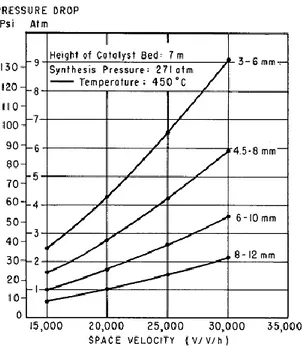
The size and shape of catalyst is determined by two factors: catalyst performance and pressure drops. While smaller and more irregular particles allow catalyst performance to be increased, they also result into higher pressure drops. Moreover, under a certain size, there is the risk of fluidizating the catalyst. To make an idea, suffice it to say that an increase in granular size from 1,5-3 mm to 6-10 mm entails an increase in catalyst volume requirement of around 23% (3). The effect of granular size and space velocity (defined as standard cubic meters of gas processed per hour per cubic meters of catalyst) on pressure drops is shown in figure 3.
Also others catalysts are feasible, the most promising being those Ruthenium (Ru)-based. The use of Ru catalysts, with Cs or Ba as promoters, allows levels of activity one order of magnitude higher than the iron-based ones, with also a lower inhibition by ammonia(7). Despite those second-generation catalysts have already been tested in industry, their use is very limited because of their high cost.
Pure iron (Fe) cannot be used as catalyst since it deactivates very fast due to sintering. A structural promoter
(such as Al2O3) should be therefore used as support to sustain Fe and so to promote catalyst performance,
allowing an operative life of catalysts exceeding a decade (7). The Fe-based catalysts are easily poisoned by oxygen compounds, the most common being water and carbon oxides (e.g. CO and CO2). A distinction should be made between irreversible (which causes permanent damages to the catalyst) and reversible poisons. The compounds mentioned above (water and carbon oxides) can be classified as reversible, as the activity loss is gradually recovered when they are no longer present in the gas. Anyway, the continuing exposure to these Figure 3: pressure drop in the synthesis reactor over
18 compounds (prolonged for more than 3-6 days), especially at high temperature and high concentration, can lead to an irreversible loss of activity of catalyst. This is probably the main cause of the decline of converter performance over the course of catalyst operative life. The content of those compounds at the reactor inlet should be reduced to ppm (usually no more than 5 ppm, corresponding to 12-15 ppm in the fresh synthesis gas entering the loop). On the other hand, sulphur, phosphorus, chlorine and arsenic compounds have an irreversible poisoning effect on Fe-based catalysts even at contents lower than one ppm. Fortunately, in methane-fed plants, the only poison of some relevance is sulphur, which is eliminated in a first stage, as seen later on in this chapter.
In modern plants the synthesis pressure is around 150-250 bar (7), which is more than a hundred bar lower than pressure used in old plants, thanks to the increase in catalysts performance, allowing a reduction of compression costs.
In the light of what has been said above, the reaction optimal temperature is a compromise between two opposite needs. In fact, the reaction rate for a catalytic reaction is proportional to the product of three factors: the first is the kinetic factor, which increases roughly exponentially with temperature according to the Arrhenius law; the second is the driving-force group, which indicates how far the system is from equilibrium (in our case it would require the lowest possible temperature); the third is the adsorption group, which accounts for the speed at which reactants and products are adsorbed and desorbed, respectively. The relation between the reaction rate and the thermodynamic state of the system is called rate equation and depends on the reaction path and so on the catalyst employed. The catalyst therefore dictates the minimum operative temperature of the process: under a certain temperature, the kinetic is too slow.
Figure 4a: reaction rate as a function of ammonia concentration for a temperature of 400°C at several pressures. Figure 4b: reaction rate as a function of temperature for several pressures for an ammonia content of 12% (8).
Figure 4a shows the reduction in reaction rate as the ammonia concentration increases. Figure 4b shows that for a pressure of 200 bar and an ammonia content of 12% the optimal temperature for maximising the reaction rate is around 490 °C. However, as appreciated, the reaction rate collapses at a slightly higher
19 temperature due to the decrease of the driving-force group. In modern plants the reactor outlet temperature is usually around 440-490 °C with an ammonia content of 17-21%.
The optimal temperature depends also upon the ammonia concentration. At the reactor inlet, where the ammonia concentration is low, the system is far from chemical equilibrium, and so the driving-force is high. Therefore, it is advantageous to operate at higher temperature at reactor inlet in order to increase the kinetic factor. As the gas reaches the exit of the reactor, the ammonia content increases, and the limiting factor becomes the driving-force group. Consequently, to maximize the reaction rate along the end of the reactor is therefore necessary to reduce the temperature. Since at the outlet temperatures mentioned above the kinetic is quite slow, for economic reasons, the reactors are usually not designed to reach chemical equilibrium at the exit.
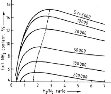
The last operative parameter to be discussed is the hydrogen to nitrogen ratio in the inlet gas. As can be seen
from the figure below, the NH3 production rate shows a maximum for a certain value of this ratio. This optimal
values increases when the space velocity of the gas decreases, reaching a value of three for low space velocities. The reason is that equilibrium plays a greater role at low space velocities. Usually this ratio is adjusted to three, because, in most plants, conversion near equilibrium is attained (3).
Figure 5: outlet ammonia content as a function of H2/N2 ratio at the
inlet for several space velocities (SV) with a pressure of 97 bar(3)
The space velocity is itself an important parameter. Sure enough, its optimal value decreases when the pressure decreases. For example if the pressure raises from 150 bar to 800 bar the space velocity can be
increased from 12000 h-1 to 35000 h-1(3). Even if at higher space velocities the ammonia content in the
effluent gas is lower, the increase in gas flow overcompensates it. This characteristic can be exploited to maintain a good ammonia production rate when catalyst ages, at least until the heat released by the ammonia synthesis reaction suffices to heat up the reactants to the required temperature.
The features briefly discussed above are the fundamentals to explain how the reactors are devised. As seen, to maximize the reaction rate throughout the whole reactor, and so obtain the highest reactants conversion with the smallest reactor (and catalyst) volume, the gas temperature should be very high at the inlet (the optimal value is above 600 °C) and it should be reduced gradually as the conversion proceeds, following the
20 optimal temperature profile. Unfortunately, the fact that the reaction is exothermic makes this temperature control very difficult to accomplish in practice.
The reactors can be classified into two main families depending on the way the gas is cooled down. In the first type of reactors the gas is “internally” cooled, with cooling tubes running throughout the catalyst bed or with catalyst inside the tubes and cooling medium on the shell side. These reactors are known as tube-cooled converters. In this case the cooling medium is usually the reactor feed gas. This class of reactors has some disadvantages related primarily to the low gas-gas heat exchange coefficient, such as an inaccurate temperature control (especially temperature peaks are very difficult to restrain) and a significant volume of the equipment. For these and other reasons this kind of converters is suited only for small production capacities and therefore of limited interest.
Figure 6: Counter-current tube-cooled converter (by Tennessee Valley Authority)(3)
Figure 6a shows an example of such reactor. The main flow enters in d, goes up through the heat exchanger (b) reaching around 200 °C and then is further heated inside the cooling tubes (c) to around 400 °C before being introduced into the catalytic bed (a). The flow entering in e is the vessel wall cooling gas that is mixed with the main flow in the reactor bottom. The flow entering in f is the main cooling stream. The gas temperature profile along the reactor is shown in figure 6b, while figure 6c shows the actual temperature profile against the ammonia content compared to the optimal profile (dotted line, a) and to the equilibrium temperature profile (v=0). It is a characteristic common to all the ammonia reactors that the gas enters at a temperature well below the optimal one, and then it increases due to the exothermicity of the reaction over the optimal value.
In the second and by far the most widespread type of reactors, the conversion takes place in adiabatic inter-cooled catalytic beds. In this configuration, the gas can be inter-cooled down between two beds placed in series in two ways: either with a cold feed gas injection (named “cold shot”) or with an indirect cooling, usually using boiling water. In the first cooling case, the converters are known as quench converters, whereas in the second as indirectly cooled multi-bed converters.
In quench converters only a fraction of the feed gas enters the first bed with a temperature around 400 °C. The catalyst volume is chosen so that the outlet temperature in each bed is around 500°C, which is limited
21 by the maximum temperature that catalyst can withstand (e.g. around 530 °C (3)). Before it enters the second stage, the gas is “quenched” by injection of cool feed gas (at 125-200°C). The same applies to subsequent beds. In this way the gas temperature follows a zig-zag path around the maximum reaction rate path, as shown in figure 7c.
Figure 7: Multi-bed converter with quench cooling (3)
The most important disadvantage of this configuration is that not all the feed gas passes over the entire catalyst volume leading to the formation of a considerable amount of ammonia in the last beds, where the ammonia content is already high and therefore the reaction rate low. Consequently, a higher catalyst volume is required, compared to the tube-cooled converters seen above. The advantage is that no extra space is required for inter-bed heat exchangers.
Even if quench converters have seen a great success in the 60’s and 70’s for their mechanical simplicity and good temperature control, in the very last decades they are rapidly losing ground in favour of indirectly cooled converters. In these converters the heat exchanger between two consecutive beds is usually installed inside the pressure vessel (as depicted in Figure 8). However, an interesting alternative, especially for large plants, is to accommodate the beds in several vessels with an indirect cooling in between (3) (as shown in Figure 9). Note that the temperature profile shown in figure 8 is improved compared to the previous case.
Figure 8: Multi-bed converter with indirect cooling(3)
22 With this concept it is possible to recover the reaction heat producing high-pressure steam (usually in the range 95-125 bar, which corresponds to temperature over 300°C, as shown in figure 9) and to reduce the equipment volume.
Another important feature to note is the direction of the reacting gas along the bed. In axial flow converters (such as those shown in figures 6-7-8), since it is not possible to increase the bed diameter above a certain
limit, it is necessary to increase the bed height to rise the NH3 production capacity. To limit the pressure
drops it is hence necessary to use bigger catalyst particles, which have a lower activity. For this reason, big capacity converters nowadays are designed with radial-flow (see figure 10). In this way it is possible to design big converters with relatively small pressure drops. A successful axial-radial flow pattern has been developed and commercialized by Ammonia Casale (now Casale, see figure 11).
Figure 10: Radial-flow quench converter by Uhde. Figure 11: axial-radial flow converter by Ammonia Casale Figure 9: temperature-enthalpy diagram for a two-bed
23 The severe conditions of high pressure, high temperature and high hydrogen partial pressure place strict requirements on the design and construction material of converters in order to reduce the hydrogen attack (hydrogen has a very high diffusivity coefficient and tends to bond with carbon forming methane, which can then produce “pockets” in the steel), nitriding (caused by ammonia reaction with the steel surface) and stress corrosion cracking (7). Almost all converters consist of an outer pressure vessel containing a separate inner vessel, cooling synthesis feed gas flows between the two, allowing the use of cheaper materials for low-temperature external vessel (typically low-alloyed chromium-molybdenum steels). The most critical components, such as the internal “baskets”, are constructed with stainless anti-corrosion steel (often Incoloy(7)).
Finally, typically operating conditions for modern synthesis loops at 220 and 140 bar are reported below (3). Consider that at 200 bar, 450 °C (which are typical outlet conditions) and 10% inerts at inlet, the ammonia content at equilibrium is around 22,2%, while the actual content doesn’t exceed 20,5%. The reactants conversion per pass is in the range 25-35% (with an upward trend in most recent plants), for this reason it is mandatory, once the ammonia has been condensed and collected, to recycle such reactants. We will see the whole ammonia loop in chapter 2.1.2.
Figure 12: typical ammonia loop conditions
2.2) Modern ammonia production plants
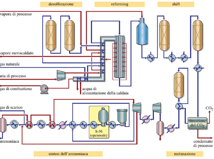
The scope of this section is describing the most widespread process for producing ammonia, the steam reforming of natural gas. The process can be divided into two main sections. The aim of the first section is to obtain a syngas with the best possible composition to be introduced in the subsequent ammonia synthesis loop section. In the second phase the ammonia synthesis takes place. Although the complete process scheme of an ammonia production plant will be proposed and analysed in chapter 3, the main steps of the process are discussed in this chapter.
24
2.2.1) Syngas production
Based on the stoichiometry of the ammonia production reaction (1), a synthesis gas with a hydrogen/nitrogen ratio of 3 should be introduced in the synthesis reactor. It is clear from the outset that the chemical process used for producing this syngas is decisive for the efficiency and the sustainability of the whole plant. The most widespread technology for ammonia production is based on the steam reforming of natural gas according to the block diagram illustrated in the figure 13 below, which is explained in detail in the following sections.
Figure 13: flow diagram of ammonia production through natural gas reforming (5)
2.2.1.1) Feedstock pre-treatment
In the first stage of the process, the desulphurization of natural gas takes place. Sulphur compounds present in the natural gas feed are poisonous for the catalysts employed in reforming, water-gas shift and ammonia synthesis reactors (see below), and should be therefore removed before entering into these reaction stages. There are several techniques for carrying out the desulphurisation of the natural gas. Adsorption on activated carbon or on molecular sieves can be employed for natural gas feedstocks with a low sulphur concentration. Nevertheless, the most common system for desulphurization consists of a non-regenerative two-stage high- temperature process. Natural gas is first mixed with hydrogen (to obtain a hydrogen concentration of around
25 2%) and heated to 350-400 °C to be fed to a first hydrogenation stage, where the organic sulphur compounds
react with hydrogen to obtain hydrogen sulphide (H2S) on a cobalt-molybdenum catalytic bed. Afterwards,
formed H2S is irreversibly adsorbed on a second zinc oxide (ZnO) bed to form water and zinc sulphide (ZnS), which is separated in solid state. Since the amount of sulphur compounds to be removed is usually very low, this desulphurisation stage doesn’t affect the energy balance of the system, and consequently the reactor outlet temperature and composition can be assumed equal to that of inlet. Using this desulphurisation process, the sulphur content in the natural gas can be reduced to less than 0.01 ppm (12).
Before being introduced in the primary reforming reactor, the feedstock, in some new plants, can undergo a
pre-reforming stage. The aim of this stage is to break down the hydrocarbons heavier than methane (C2+)
present in natural gas into CO and H2, through the following steam reforming reaction:
CmHn + mH2O ↔ mCO + (n/2+m)H2
At the high reforming temperatures, heavy hydrocarbons are prone to decompose into solid carbon through thermal cracking. Carbon formed may deposit on the catalyst surface, leading to catalyst deactivation, and on pipes’ surfaces, through a mechanism typically known as fouling. Carbon deposit on pipes’ surface results in a lower convection coefficient on the inner tubes side (due to the added conduction heat resistance) that would lead to a superheating of pipes, which can be consequently damaged, and to an even faster deposition in a feedback loop. A preliminary pre-reforming stage of the natural gas would therefore avoid all these effects.
Before the pre-reforming stage, the feedstock is mixed with steam (usually drawn from the steam turbine) and heated to around 490-530 °C (3) before being sent to the pre-reformer. In the outlet stream the
concentration of C2+ hydrocarbons is usually very low (ppm). Since the reforming reaction is endothermic
(the syngas exits in equilibrium with steam reforming and water-gas shift, see next chapter), the outlet temperature is lowered by 30-80 °C, depending on the concentration of heavy hydrocarbons.
The use of a pre-reforming stage allows the steam to carbon ratio to be reduced, to reduce the charge of fired tubular reformer, to extend the life of FTR catalysts and pipes and to process heavier feedstocks. Besides, through pre-reforming, some middle-temperature heat is converted into syngas chemical energy, reducing the amount of fuel to be spent.
2.2.1.2) Steam reforming
The natural gas steam reforming process is the most widespread way to produce hydrogen. Considering that methane is the main constituent of natural gas, main reactions occurring in the steam reforming process (steam reforming and water gas shift reactions) can be written as follows. :
CH4 + H2O ↔ CO + 3H2 (ΔHr° = 206 kj/mol,CH4) steam reforming (SR) (2)
CO + H2O ↔ H2 + CO2 (ΔHr° = -41 kj/mol,CO) water-gas shift (WGS) (3)
The SR reaction is strongly endothermic, which means that a source of heat (internal or external) is necessary to sustain the reaction and that its equilibrium constant (and so the methane conversion) increases with temperature. Consequently, from a thermodynamic point of view, the SR has to be performed at the highest possible temperature for maximising methane conversion. However, maximum temperature is determined by the materials’ reactor resistance as well as the catalyst performance.
26 The SR reaction implies doubling the molar flow, and so an increase in volumetric flow. According to Le Chatelier’s principle, an increase in the operative pressure leads to a shift in the equilibrium position towards the species which occupy the smaller volume. Then, the SR reaction should be performed at a low pressure in order to maximise the methane conversion. Typical values for the pressure of the steam reformer fall down in the range of 25-40 bar. The reasons for such a high value of operating pressure are economic ones, since the plant components have to be as compact as possible to reduce their cost and the products are usually needed at a high pressure. Moreover, methane is often available at high pressure from the grid and, due to the stoichiometry of the reaction, syngas compression is more energy demanding than compressing reactants.
The ratio between carbon monoxide and dioxide in the outlet stream is itself affected by the temperature. Since the WGS reaction is exothermic the CO/CO2 ratio increases as temperature increases.
Figure 14: methane slip as a function of pressure, temperature and steam to carbon ratio(6)
The steam reforming process is globally endothermic (the heat released by the WGS is too low to balance that absorbed by the SR), and it is hence necessary to furnish the required heat somehow. This can be done in two main ways. The first way is to furnish it from outside the reforming reactor. In most of the hydrogen production plants the reforming process takes place inside of thin and long pipes (usually 7-13 cm diameter and 7-12 m length(6)), arranged inside a furnace where additional natural gas is burnt with air. The heat is therefore primarily exchanged through radiation. Those plants are known as fired tubular reformers (FTR). In this case the outlet temperature of the reformed stream is around 890-910°C which corresponds to a pipes outer wall temperature around 950 °C (6). Otherwise the heat can be supplied within the reforming reactor such as in auto-thermal reformers (ATR). In this case, air is fed to the reactor together with natural gas and vapour (usually the oxygen to methane ratio is around 0,6 (6)). Two reaction zones can be distinguished: in the first one, the combustion reactions dominate, releasing the heat necessary to sustain the reforming process, which takes place in the second catalytic zone. In this way the reactor is simpler and cheaper than in the FTR plants, and higher temperatures are permitted since there is no pipes wall temperature to be controlled, allowing a reduced methane slip to be achieved. The outlet temperature is usually in the range 950-1100 °C. As some water is produced through combustion, the steam to carbon ration can be reduced to 1-2 (where the values for FTR are in the range 2,5-4,5), with benefits for the plant energy efficiency. In both cases a Nickel-based catalyst is usually employed, made up of 15-25% of NiO on an aluminium oxide, calcium nitrate or magnesium aluminium spinel support (3). However, ATR reactors do have a disadvantage that makes them inconvenient towards FTR in conventional size hydrogen plants. If oxygen is supplied with air, nitrogen behaves like an inert, absorbing the heat of reaction and making necessary a larger amount of natural gas to be oxidised for fulfilling the energy balance. Moreover, in this case, hydrogen obtained is
27 diluted with nitrogen coming from air, requiring the subsequent separation of nitrogen from hydrogen when it is needed in its pure form. For these reasons in ATR plants for hydrogen production, oxygen is usually supplied almost pure (e.g. with O2 purities around 95-97%) from an air separation unit (ASU), which is itself an expensive, heavily affected by economy of scale and energy-demanding system (the primary energy
required is around 0,6 kWh/Nm3,O
2). The need of this ASU, when focused on hydrogen production, makes
ATR plants more economically convenient when moving for large hydrogen production scales.
When focussing on ammonia production, an ATR-based syngas production system seems suitable since in this case the presence of nitrogen in the syngas is needed for the ammonia production process (a hydrogen/nitrogen ratio of 3 at the synthesis reactor inlet is needed). However, if the whole reforming process took place inside the ATR (supplied with air), in order to achieve the outlet temperature requested to reduce the methane slip to a reasonable level, say 1000 °C, a quantity of nitrogen far greater than the requested would be supplied, leading to the disadvantages explained above. For this reason, the reforming reaction has to be split into two sections. The first phase takes place inside a FTR reactor (primary reformer), where a partial conversion of methane is (intentionally) obtained, and afterwards the products are then sent to an ATR unit (secondary reformer). The conversion of methane in the first phase has to be determined so
that the amount of nitrogen required to obtain the H2/N2 molar ratio at the ammonia synthesis reactor
corresponds to the amount of air required to close the energy balance at ATR (that is an outlet temperature around 1000 °C which corresponds to a residual methane content lower than 0,5% on dry basis (3) and a methane slip around 1,25%). Usually the methane conversion in the first stage is in the range of 55-65 %. Since the methane conversion in FTR is limited, the outlet temperature can be itself limited (to around 780-820 °C), reducing the heating duty on FTR (which is energetically less efficient than ATR) and the piping thermal stress. For the same reason, even the FTR designing should be, at least theoretically, different from those used for the production of hydrogen. In this case, actually, it is not necessary to give the reactants the time (namely the space) to reach chemical equilibrium. The outlet temperature and the tube length (once established the superficial velocity) are both designing parameters. For a given methane conversion, decreasing the FTR outlet temperature results in a strong reduction of its heating duty and so in a strong increase of that of ATR, not only because of the reduction of the sensible heat of the reformed stream but also for the reduction of its chemical energy, due to the exothermicity of the WGS reaction. The other designing parameter is the process air temperature, which is usually varied in the range 520-610 °C to adjust the ATR outlet temperature. The steam to carbon ratio employed is in the range 2,8-3,5(3), with a trend towards the lower bound in the most modern plants. The optimum pressure value is around 30-35 bar. Once set the ammonia synthesis pressure (in the range of 150-250 bar as we will see later on), reducing the syngas production pressure results in a reduction in unconverted methane but in an increase in the compression energy costs.
28
2.2.1.3) Water-gas shift
The syngas obtained from ATR contains a substantial amount of carbon monoxide (in the range of 13-14% on
a dry basis). This compound has to be converted into further H2 and CO2 through the WGS reaction for two
reasons. On the one hand, CO has a high heating value, which can be exploited to produce further hydrogen that will be ultimately converted into ammonia. On the other hand, iron based catalyst employed in the
ammonia synthesis reactor is poisoned by almost all oxygen compounds, going from CO to CO2 or H2O.
Whereas it is quite easy to separate CO2 from syngas, for example using a MDEA process, the same doesn’t
apply to CO (7).
Since the WGS is slightly exothermic the CO conversion into CO2 and H2 is favoured at low temperatures.
When looking for high CO conversions, it is common to place two (or more) WGS adiabatic stages working at different temperatures with an intermediate cooling stage between them. High temperature heat recovered from the intermediate cooling can be exploited for producing high pressure steam, which will improve the system efficiency.
The syngas enters the first WGS stage at a temperature around 330-360 °C and exits at 410-440 °C, while the CO content slips from 12-16% to 3-3,5% (dry basis). The catalyst employed in this stage is typically iron-based, with the addition of chromium (up to 10% by weight) as a structural stabiliser, and of a little amount of copper (1-2%) as a chemical promoter (7). Such catalyst is active in the range 300-500 °C (3). Afterwards, syngas is cooled to 200-210 °C before entering in the second WGS stage. This temperature is dictated by the syngas dew-point temperature and by the catalyst activity (7). At LT-WGS reactor outlet the syngas has a temperature of 225-235 °C and a CO content of 0,1-0,3%. The catalyst employed in this stage is made up of
a mixture of copper oxide (CuO) (by 40-60%) and zinc oxide (ZnO) (by 20-30%) supported over alumina (Al2O3)
(3), which acts as a structural stabiliser.
2.2.1.4) Syngas purification
Syngas exiting the second WGS section contains around 18% of CO2 (dry basis), a small amount of CO and a
great amount of H2O. As already mentioned, these compounds are poisonous for the ammonia synthesis
catalyst and therefore their concentration must be reduced to ppm. Water is typically removed by condensation, as shown in a next chapter.
The classical method for CO2 removal is based on scrubbing the syngas under pressure with a solvent capable
of solving carbon dioxide in a column equipped with trays or packings. Both chemical and physical solvents
can be used, depending on the CO2 partial pressure in the gas phase. In the case of interest, the CO2 pressure
is in the range of 4-7 bar, which makes chemical solvents (e.g. alkanolamines) usually the preferred option. Primary and secondary amines, such as MEA or DEA, exhibit a high mass-transfer rate but have an high energy consumptions during regeneration (3). For this reason, tertiary amines (e.g. MDEA) are commonly
used today. In this case, the CO2-laden solvent is flashed, usually in steps, to around atmospheric pressure,
and the spent scrubbing liquid is heated and regenerated in a stripping column, before being recycled in the scrubbing column The heat requirement for amine regeneration in this case is strongly dependent on the process employed. For example the one-stage MDEA process developed by BASF requires 73kj per mole of
29 Alternatively to absorption with amines, physical solvents represent also a feasible option for CO2 removal (e.g. Selexol process). However, they have the disadvantage of a high capacity for adsorbing water, making necessary the previous cooling of gas to around 5 °C to separate the water. Besides, adsorption is favoured at cryogenic temperatures, leading to a high cooling cost.
Concerning the MDEA process, the heat needed in the reboiler of the stripping column is supplied by
low-temperature (125-130 °C) vapour condensation, in order to reduce the volume of the equipment. The CO2
removal efficiency reached in ammonia plants is in the range 98-99,9% (3,7). Usually the low-pressure steam is generated downstream the LT-WGS reactor, cooling the syngas to around 140-150°C. The syngas is then further cooled to around 35 °C in order to condensate the water (which is collected before the MDEA process) and to reach the optimal conditions for the absorption column. The syngas exiting the MDEA process has a
CO2 and CO contents of 0,01-0,3% and 0,2-0,5% (dry basis) respectively, which are still too high for the
tolerance of the catalyst used in the synthesis reactor.
The most common and cheap way to remove the remaining carbon compounds is through “methanation”.
The gas exiting the CO2 removal stage is heated up to 260-290 °C (usually using the gas exiting the methanator
itself) to be sent to the adiabatic methanation reactor in the presence of a Nickel-based catalyst. At these low temperatures the equilibrium constant of the SR reaction is quite low, so that the reaction proceeds backward, producing CH4 and consuming CO. The consumption of CO through the methanation reaction
pushes the reverse WGS reaction (e.g. CO2 conversion into CO). Despite some hydrogen is reconverted into
water and some more inerts (CH4) are produced, the low outlet carbon oxides concentration (below 10 ppm)
makes this stage advantageous. The higher is the CO2 removal section efficiency, the lower is the hydrogen
loss and the methane production. Since the process is globally exothermic, some attention has to be paid to
the outlet temperature. Usually the temperature rise is around 50-70 °C, but if a CO2 slip from the CO2
removal system occurs, the outlet temperature can quickly exceed 500 °C.
Both the removal of CO2 and the methanation process entail the increase of water partial pressure in the
hydrogen rich gas. Consequently, the gas is cooled again to 30-35°C, depending on the temperature of cooling
water available, to condensate the H2O present and separate it before entering into the ammonia synthesis
reactor. The water content is reduced in this way to around 0,16-0,14%. The gas is now sent to the compression train of the synthesis loop.
2.2.2) Ammonia synthesis loop
In the compression train, the syngas is compressed from a pressure of around 25-30 bar up to 150-250 bar (over 300 bar in old plants; note that at these pressures the ideal gas hypothesis no longer stands). One of the most important features of the single-train plant pioneered by M. W. Kellogg in 1963 was the use of centrifugal compressors to compress the synthesis gas (and recycle) in the ammonia loop, as well as process air and refrigerant (in the refrigeration cycle). Since then, application of centrifugal compressors has become standard practice in almost all ammonia plants. In spite of the lower efficiency compared to reciprocating or axial compressors, these machines have also important advantages: a low investment cost (because of the higher compression ratio per stage compared to axial compressors and because single machines have been developed even for large capacities), low maintenance costs, less frequent shutdowns for preventive maintenance, high reliability and small space requirement (3). As mentioned above, in most cases they are
30 directly driven by the steam turbine (fed with heat recovery system steam), avoiding the losses associated with conversion and transmission of electrical power. The maximum wheel tip speed is limited to around 330 m/s by the tensile strength of the steels used. This means that a pressure increase from 25 to 200 bar would require 18-20 impellers. However, a compressor shaft can accommodate no more than 8-9 impellers, in order to avoid excessive vibrations. It is therefore necessary to accommodate several compressor casings in series (usually 3, or 2 in low-pressure ammonia loop plants), with a compression ratio of 1,8-3,2 each (3). Since it is necessary to recompress the recycle gas before sending it into the converter, because of the pressure drops, the shaft of the final casing also bears the impeller for the compression of the recycle gas (3). The feedstock is cooled down to 40-50 °C, depending on the temperature of the cooling water available, before the second and, if present, the third compressor, reducing the compression power consumption. In this way is also possible to condense and collect some of the residual water, which can then be almost totally removed by an adsorption system.
The ammonia loop can be performed in three main ways, sketched in figure 16.
Figures 16a-b-c: three main ammonia loop concepts. Where 1 is the ammonia converter, 2 is the ammonia separator, 3 is the recycle compressor, 4 is the fresh feed, 5 is the purge, 6 is the liquid ammonia(7)
In any case, it can be noted that a purge stream is necessary, in order to keep a constant inert content (CH4
and Ar) at the converter inlet (usually around 7-12%). The purge ratio (defined as the ratio between the purge flow and the purge split inlet flow) is an important parameter, which has to be optimized. On the one hand, increasing the purge ratio leads to a reduction both in the flow entering the reactor and in its inerts content, allowing a reduction of the equipment (and catalyst) volume and an increase in ammonia content at the converter outlet. On the other hand, more reactants are thrown out, leading to a loss of ammonia production efficiency. Anyway, the purge ratio is very small (1-1,6% as order of magnitude), which means that the great majority of the flow entering the converter comes from the recycle (the recycle mass flow is usually three-fold or more the fresh gas mass flow).
In the scheme in figure 16a both the purge split and the fresh syngas inlet are placed downstream the ammonia separator. This is the most efficient scheme because the ammonia is collected before being diluted with the fresh gas, and so at its highest partial pressure, whereas the purge is pulled out at the lowest ammonia content. In this way the ammonia content at the synthesis reactor inlet is the lowest possible. Moreover, the gas flow to be compressed is the lowest, since the ammonia has already been removed. However, the main disadvantage of this scheme is that all the impurities present in the fresh gas are directly introduced in the synthesis reactor. Therefore, in case this ammonia loop scheme is used, it is necessary removing efficiently any impurity present in the syngas before the ammonia synthesis process as well as using lubricant-less compressors (such as centrifugal ones (7)), in order to avoid the presence of lubricant on the catalyst. Otherwise, if the impurities content in the feed gas could be harmful for the catalyst, the feed can be introduced upstream the ammonia separator (figures 16b-16c), so that the impurities can be absorbed
31 and removed by condensing ammonia. Scheme in figure 16b has the advantage of a lower mass flow to be compressed compared to that in figure 16c, since the ammonia has already been drained at the compressor inlet. On the other hand, the compressor in scheme 16b has to be designed so to avoid the mixing between the fresh gas and the recycle (in fact, scheme in figure 16b is referred to as “4 nozzles scheme” while that in figure 16c as “3 nozzles scheme”).
The ammonia is removed by condensation, which is favoured by the high pressure of the loop. It is hence necessary to cool the ammonia-rich gas as much as possible, in order to reduce to a minimum the ammonia content in the recycle. The cooling is performed in a series of heat exchangers, in order to exploit the temperature levels available in the most efficient way. Usually, in modern plants, after the ammonia-laden gas has been cooled down with recycle gas and, then, with cold water, to around 30-45 °C (depending on the temperature of the water available), it is further cooled down with a refrigeration cycle to around -25°C (3,7). Compression cycle with ammonia as refrigerant fluid is usually employed, with one or more temperature levels. The refrigeration energy cost is significant because of the high compression ratio (usually the ammonia in the cycle evaporates at around -30 °C or less, and condenses at 35 °C at least, corresponding respectively to a pressure of 1,1 and 17 bar) and the relatively high mass flow to be cooled (since the ammonia content in this stream is relatively low, as a consequence of the low conversion per pass). It is therefore very important to design the synthesis loop and the refrigeration cycle with the aim to reduce such cost. The liquid ammonia obtained is flashed to around 20 bar in a let-down vessel to release the dissolved gases. Such gases are usually scrubbed to remove evaporated ammonia and then used as fuel in the primary reformer. The low-temperature purge (stream 5 of fig. 16) is scrubbed with water to remove the ammonia (which is highly miscible in water) at around 135-145 bar (3), reducing the ammonia content to less than 200 ppm.
This step is necessary in order to limit the NOx formation, since the purge is used as fuel in the fired tubular
reformer combustion chamber. Usually the scrub system is composed of two scrubbers, one at low pressure in which the low-pressure desorbed gases are washed, and one at high pressure for washing the purge. The laden water is regenerated in a stripper, from which the gaseous ammonia is separated from water (10). Since the purge flow is very low and its ammonia content is relatively low as well, the energy regeneration cost is negligible.
Since the purge gas contains mostly hydrogen, it can be advantageous to recover and recycle it. There are three main ways to do it. When cryogenic units are employed, after the scrub, ammonia is completely removed by molecular sieve adsorbers, the dry ammonia-free gas is sent into the cold box, where it is cooled down to around -188 °C(3), partially liquefying methane and argon (and some nitrogen). The liquid inert-rich phase is flashed and the resulting gas is used to cool the inlet gas and then sent into the combustion chamber. The gas phase contains mainly hydrogen. The hydrogen recovery efficiency for cryogenic units is around 90-95% (25% for nitrogen, 25% for argon and 4% for methane(7)). An interesting alternative is the membrane separation (for instance Monsanto’s Prism), exploiting selective gas permeation through membranes to separate them. In this case there is no necessity for an advanced dryer and ammonia-removal system. Since the rate of permeation decreases along the separation bank, due to the decrease in hydrogen partial pressure, usually two separators operate in series, the second one with a lower pressure on the sweep side. In this way two streams of permeated hydrogen are obtain, the first up to 70 bar, the second around 25-28 bar (3). The overall hydrogen recovery is around 90-95% with a high purity. The third and probably the most widespread way to recover the hydrogen is the “pressure swing adsorption” (PSA). The process was initially developed by Union Carbide, under the name HYSIV, and then marketed by Honeywell UOP, under the name Polybed PSA (3). Currently it is commercialized by several companies. This process exploits the different adsorption capability of solid beds (usually zeolites) for different gases: the hydrogen crosses the bed uncaptured while other gases remains trapped in the solid pores. The bed is then regenerated reducing the
32 pressure. In this way a high-pressure (up to 60 bar) hydrogen stream and a low-pressure purge gas stream
are obtained. The hydrogen recovery efficiency can reach 90%, with final H2 purities higher than 99.999% (7).
2.2.3) Performances and improvements
Typically, for evaluating the performance of an ammonia production plant, the key parameter is the primary energy consumption (in GJ) required to produce one ton of ammonia. If there is an electric energy or vapour export/import into the ammonia production plant, it can be taken into account in this energy consumption by adding or subtracting the primary energy related to their production. It has to be noted that the parameter itself is prone to a certain ambiguity, since it is affected, for example, by the ammonia phase (the delivery of 3 bar ammonia vapour allows a reduction of 0,6 GJ/t compared to liquid ammonia at ambient temperature, while delivery as liquid at -33 °C would need an extra 0,3 GJ/t(3)). Anyway, ammonia is usually delivered liquid at ambient temperature at 17-20 bar, so this is probably the most logical reference conditions to be used for performance comparison. There are also external factors affecting the performance, the most Figure 17: process scheme of an ammonia production plant by Haldor Topsoe(7)
33 important one is probably the temperature of the available cooling water: an increase from 20 to 30 °C entails an increase of around 0,7 GJ/t in energy consumption(3). Also the natural gas composition plays a role. It is possible to evaluate the theoretical minimum energy consumption referring to the ammonia synthesis reaction from methane, air and vapour:
CH4 + 0,3035 O2 + 1,131 N2 + 1,393 H2O ↔ CO2 + 2,262 NH3 (ΔHr°= -86 kJ/mol)
As can be seen, from 1 kilomole of methane (corresponding to 0,8 Gj of primary energy), 2,262 kilomoles (or 38,454 kg) of ammonia are obtained, which means that the theoretical consumption is 20,9 GJ/t. In the figure below the performance of actual ammonia production plants are shown. The current reference value is around 28 GJ/t (but technology would be available to reach 27 GJ/t (3)). As can be noted, great improvements have been achieved from the dawn of the technology to the present day.
Figure 18: ammonia plants primary energy consumption throughout the years compared to the theoretical value(3)
Almost 70% of the exergy losses of the process occur in the reforming section (primary reforming particularly) and in the steam generation (3). From a first-law analysis it can be seen that almost all the losses are transferred to the cooling water, meaning that a great deal of low-temperature heat is produced. Therefore, the water heat integration system plays a remarkable role in the overall efficiency.
Finally, the carbon dioxide emissions minimum value, if the carbon dioxide captured by MDEA is stored, is
around 0,35-0,38 tCO2/tNH3 for the best available technology, corresponding to 76-78% of carbon capture
ratio.
The main steps that have allowed the improvement of the ammonia production technology mentioned above are briefly listed below.
The desulphurization of natural gas, initially performed through adsorption on active carbons, has
been replaced by catalytic hydrogenation followed by absorption on ZnO pellets (see chapter 2.1.1.1).
Reforming section: reduction of the flue gas temperature, combustion air and fuel preheating,
increased operative pressure, lowering of the steam to carbon ratio, installing a pre-reformer unit, and, above all, shifting some reformer duty from primary to secondary reformer(3).
34
Shift conversion: improved LT-WGS catalysts allow a lower operative temperature and so a lower CO
content, while a new generation of HT-WGS catalysts, less prone to low-steam to carbon deactivation and hydrocarbon formation, allow lower S/C ratio to be used.
Carbon dioxide removal: modern processes, as BASF aMDEA or Benfield LoHeat, allow a reduction in
the regeneration energy duty.
Ammonia synthesis section: improved converter design (with indirect cooling), larger catalyst
volume, refrigeration cycle to condense the ammonia and hydrogen recovery systems.
Turbomachinery: developments in compressors and turbines manufacturing.
Heat recovery system: increase of pressure and superheating temperature of steam; inclusion of
steam superheater downstream of the secondary reformer(3), despite the metal dusting issue, thanks to new and more expensive material.
![Figure 7: T-Q diagram for the syngas cooling 5010015020025030035040045050055060065070075080085090095010001050051015 20 25 30 35 40 45 50 55T [°C]H [MW]hx-7hx-6hx-5hx-4hx-3hx-2050100150200250300350400450500550600650700750800850900950100001020304050607080901](https://thumb-eu.123doks.com/thumbv2/123dokorg/7518991.105897/47.892.83.803.681.1051/figure-diagram-syngas-cooling-mw-hx-hx-hx.webp)
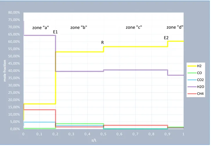
![Figure 14: stage B: axial temperature profile at an intermediate time 25030035040045050055060065070075080085090000 , 10 , 20 , 30 , 4 0 , 5 0 , 6 0 , 7 0 , 8 0 , 9 1T [°C]z/LT,g,in,Bzone "a"T,max,Bzone "b"T,ad,Azone "c"RE](https://thumb-eu.123doks.com/thumbv2/123dokorg/7518991.105897/70.892.84.806.649.1049/figure-axial-temperature-profile-intermediate-bzone-bzone-azone.webp)


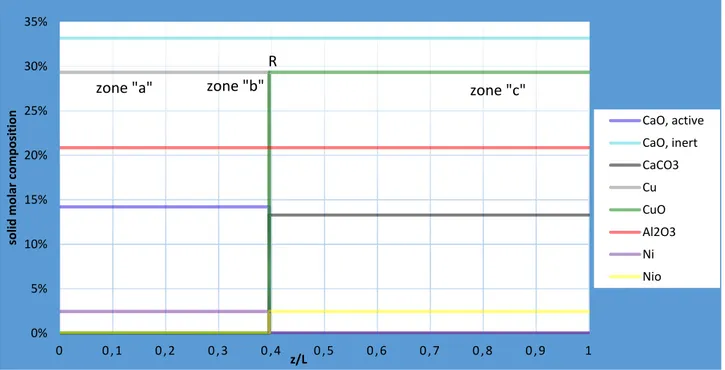
![Figure 19: stage C: axial gas molar composition profile at an intermediate time 67570072575077580082585087500 , 10 , 20 , 30 , 40 , 5 0 , 6 0 , 7 0 , 8 0 , 9 1T [°C]z/LT,g,in,Czone "a"T,max,Czone "b"T,reczone "c"RE0%5%10%15%20%25%30](https://thumb-eu.123doks.com/thumbv2/123dokorg/7518991.105897/76.892.86.805.720.1126/figure-molar-composition-profile-intermediate-czone-czone-reczone.webp)