On the crack path of rolling contact fatigue cracks in a
railway wheel steel
R. Roberti1, M.Faccoli1, G. Cornacchia1, A. Ghidini2 1
Università degli Studi di Brescia, Dipartimento di Ingegneria Meccanica e Industriale, via Branze, 38 – 25123 Brescia, Italy – [email protected]
2
Lucchini RS S.p.A., Via G. Paglia, 45 – 24065 Lovere (Bergamo), Italy
ABSTRACT. The objective of the present paper is to give some preliminary results
obtained in the frame of a more wide investigation on the rolling contact fatigue (RCF) property of the R7T railway wheel steel. The effect of different test parameters on the RCF fatigue strength of the railway wheel steel was evaluated. RCF tests were conducted using two cylindrical contact specimens under different Po/k ratio (where Po
is the maximum Hertzian pressure, k is the yield stress in shear of the material), under dry conditions and with water lubrication, and at varying slip ratio. Crack initiation location and crack growth direction were carefully investigated; microscopic examination showed that the cracks were initiated at the surface, propagated obliquely in the depth direction and then occasionally branched into two directions. Usually multiple cracks are initiated, at the rolling contact surface, caused by the accumulation of shear deformation due to repeated rolling–sliding contact loading. Subsequent crack growth has been found to occur along specific sloped directions. The influence of Po/k
ratio, dry or wet contact, and slip ratio on crack slope angle to the radial direction and the depths at which slope changes occur has been investigated. Observed crack slopes and slope change position have been discussed according to crack path prediction criteria (CPPC) in the literature.
INTRODUCTION
Research about wear and RCF of both rail and rail wheels has markedly progressed in recent years. But while wear is visible and controllable, RCF cracks are difficult to detect and potentially dangerous if left to grow. In fact, RCF cracks are one of the most important problems for the railway industry.
The life of a fatigue crack is normally divided into three phases encompassing crack initiation and growth. The phases can be divided into: stage I, shear stress driven initiation at the surface, followed by transient crack growth behaviour, and stage II, subsequent tensile and/or shear driven crack growth [1].
Also RCF crack initiation, at the rolling contact surface, is agreed to be caused by the accumulation of shear deformation due to repeated rolling–sliding contact loading.
Surface RCF cracks are usually reported to occur due to unidirectional plastic material flow caused by wheel vs. rail sliding (creepage) and high tangential forces. Once a surface crack appears it has a shallow angle to the wheel head surface. Surface cracks are generally said to follow the plastically deformed material during their early growth until they reach a (critical) length at which crack growth is governed by the stress and strain field near the crack tip [2]. At the critical length cracks may either branch upward, causing flaking of the wheel material (spalling), or grow further downward, with great danger for the wheel integrity.
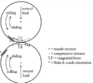
In rolling contact, the layer of material beneath the contact surface is subjected to nonproportional multiaxial load cycles. At high traction, the plastic flow is determined by the stress at the surface. The material near the surface experiences a nonproportional cycle of tension, followed by shear, followed by compression (Fig. 1). This loading gives rise to an out-of-phase rotation of the principal stress and strain direction in time, which makes it difficult to predict the position and orientation of crack initiation, and subsequent crack path.
Stage I RCF crack initiation and early transient growth are therefore a critical point in the assessment of the RCF behaviour of wheel rail steels and represent a critical step in life prediction of a fatigue crack in rolling contacts.
The present paper reports the results of some metallographic observations on surface RCF fatigue cracks produced in twin disc laboratory tests on the R7T railway wheel steel, with particular emphasis towards the crack path (orientation and branching) at initiation and in the subsequent propagation stages.
EXPERIMENTAL PART
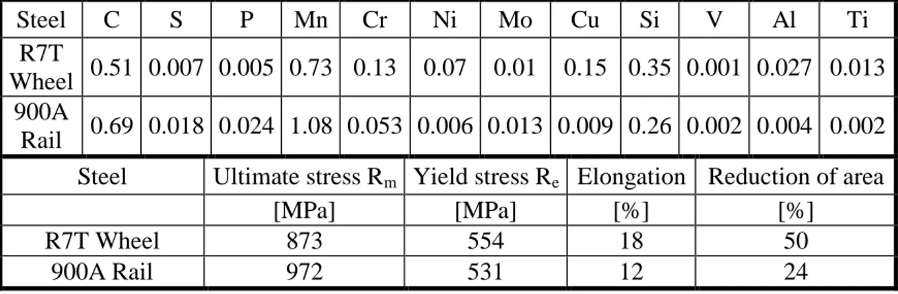
The present research work is part of a more wide investigation on the rolling contact fatigue (RCF) property of the R7T railway wheel steel. The RCF properties have been investigated by means of a twin disc Amsler machine with disc specimens machined out of a R7T steel wheel (upper disc) and a 900A steel rail (lower disc), whose chemical compositions are given in Table 1, along with the respective mechanical properties.
Table 1: Wheel and rail steel chemical composition (wt %) and mechanical properties
Steel C S P Mn Cr Ni Mo Cu Si V Al Ti R7T
Wheel 0.51 0.007 0.005 0.73 0.13 0.07 0.01 0.15 0.35 0.001 0.027 0.013 900A
Rail 0.69 0.018 0.024 1.08 0.053 0.006 0.013 0.009 0.26 0.002 0.004 0.002 Steel Ultimate stress Rm Yield stress Re Elongation Reduction of area
[MPa] [MPa] [%] [%]
R7T Wheel 873 554 18 50
Figure 1. Schematic representation of the state of stress in the two-disc rolling-sliding contact. Characteristic flake and crack orientation are shown (not to scale) for each disc
In the twin disc test the rotating speed of the disc and their relative diameter have been used to define the creepage percentage in the test. Both dry and water lubricated tests have been carried out. The tests have been interrupted at different rotating cycles, preferably in correspondence of the onset of surface disc damage observed by visual inspection.
The wheel steel discs, 10 mm thick, at the end of the test, have been cut at the midthickness in order to examine the RCF crack paths. Figure 2 (right side) shows the definition of the crack plane orientation, that in the present research work has been conventionally defined in the clockwise direction starting from the direction parallel to the tangent in the contact point. The reference axis for the angle measurement is conventionally directed in the opposite direction to the wheel disc rotation. The definition here adopted correspond to the one reported in the literature [3] (Fig. 2, left side), but has the advantage of a more simple measure.
RESULTS AND DISCUSSION
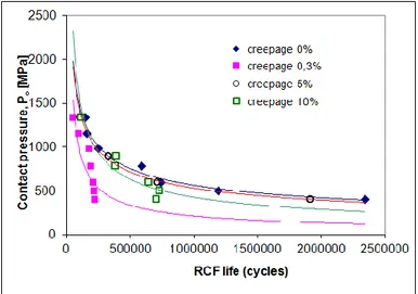
Figure 3 shows the RCF life of the R7T steel for wet contact as a function of Hertzian contact pressure and creepage [4]. As reported in the literature, creepage percentages smaller than 1% have very detrimental effect on RCF behaviour. Dry contact experiments gave absolutely longer RCF lives. Under dry contact conditions a RCF damage could be observed for the moment only in a disc under a contact pressure of 900 MPa, with 0% creepage, after 2.6·106 cycles. In the case of 400 and 500 MPa, 0% creepage, no RCF damage could be observed after 8·106 and 9·106 cycles respectively.
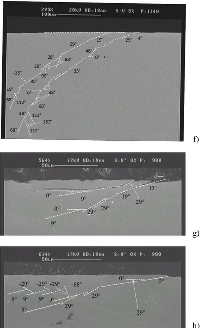
Figure 4 shows the rolling contact fatigue crack path in the R7T steel wheel discs for various test conditions.
Figure 2. Definition of the crack plane orientation, in a twin disc test, by the angle [3] (left); magnification of the contact point: definition of different subsequent crack plane
orientations in the present research work (right). The kink angle is given by i+1 - i.
Figure 3. Rolling contact fatigue life, i.e. number of cycles to damage initiation, vs. Hertzian contact pressure, for different creepage and for wet contact.
b)
c)
d)
f)
g)
h)
Figure 4. Rolling contact fatigue crack path in R7T steel wheel twin disc test; wet contact: a) contact pressure 400 MPa, creepage 0%, 2342000 cycles; b) contact pressure
400 MPa, creepage 0%, 2342000 cycles; c) contact pressure 500 MPa, creepage 0%, 1190000 cycles; d) contact pressure 400 MPa, creepage 0.3%, 216000 cycles; e) contact
pressure 900 MPa, creepage 5%, 324000 cycles; f) contact pressure 1340 MPa, creepage 5%, 109800 cycles; dry contact: g) contact pressure 900 MPa, creepage 0%,
2600000 cycles; h) contact pressure 900 MPa, creepage 0%, 2600000 cycles
From the direct observation of the crack paths it emerges that if from a general point of view the crack initiation and subsequent transient growth roughly follow the plastically deformed material, a more careful examination allows to ascertain that, while
the deformation of the material occurs along a continuously curved path, the crack growth follows subsequent straight paths along differently oriented planes, with abrupt changes from one path to the following one. The same crack plane orientation angles are observed independently of the condition of contact, wet or dry, the contact pressure, and the creepage. The effect due either to fluid-filled crack pressurization and to crack faces lubrication doesn’t therefore seem to affect the crack plane orientation angles.
Almost the same crack orientation angles have also been measured on a RCF crack reported in [3] (Fig. 5).
Crack initiation occurs in correspondence of the rolling surface, with a very low orientation angle to the circumferential direction. Subsurface initiation has never been observed also in the case of favourable circumstances like the presence of a large non metallic inclusion (Figs. 4e and 4h). In some cases some of the crack plane orientations are symmetrically oriented with respect to the radial or to the circumferential direction.
Crack path in RCF has been numerically investigated taking into account the general mixed mode stress field given by the opening mode stress intensity factor KI and the
shearing mode stress intensity factor KII. Several hypotheses have also been adopted for
calculation of the prediction of the initiation or branching angles of macroscopically mode I and mode II crack growth.
In [5] it was obtained that the prediction of crack growth direction shows a biunivocal relationship between the crack growth direction, and hydrostatic stresses and friction. At a sufficient high pressure the crack will extend straight ahead in its original angle. However, differently from the present experimental observation, it was also obtained that hydrostatic pressure and low friction between the crack surfaces suppress opening mode crack growth and that at decreasing hydrostatic load or friction the crack extend via kink subjected to local opening mode. The angle the kink forms with the original crack plane decreases with increasing hydrostatic pressure or increasing friction between the crack surfaces. In [6] a multiple branching propagation with defined crack plane orientations has been obtained with a starting angle of near 12° from the original subsurface 0° crack, as for the early propagation in Fig. 5.
In [7] the FE analysis has shown that two peaks of K,max occur during one cycle of
rolling contact and it was then deduced that the peaks cause crack branching in two directions, that is, in the depth direction and towards the surface, with crack plane orientations of 90° and -45° respectively according to the crack orientation definition. In the FE analysis the starting crack had a 25° plane orientation.
Also in [8] FE analysis led to point out specific crack growth directions according to the assumed contact conditions; in particular it was calculated that under full slip condition the material critical planes moves in a counter clockwise direction at increasing contact pressure, and crack growth directions tend to be flat compared with partial slip condition. Under partial slip condition, the critical plane changes in a clockwise direction at increasing contact pressure.
CONCLUSIONS
RCF crack path has been investigated in both dry or wet contact, under different contact pressure and creepage. Ratchetting strain, which is a cycle-by-cycle strain accumulation in the primary loading direction over thousands of contact cycles, is initially accumulated in railroad wheels in the direction of tangential force and a shear flow layer results. Surface-initiated RCF crack is the consequence of shear band cracking controlled by ratchetting. Due to the hydrostatic pressure the wheel material can withstand higher strain without failure compared to uniaxial or biaxial loading. Subsequent crack propagation within the plastically deformed layer has been found to follow defined crack plane orientations. Further work is needed to relate the multiaxial fatigue crack propagation governed by the general mixed mode stress field and the condition for crack branching with the experimentally observed crack path.
REFERENCES
1. Miller KJ. (1997). In: Fatigue and fracture mechanics, pp. 267–286, Piascik, R.S., Newman, J.C., Dowling, N.E., eds., vol. 27, ASTM STP 1296. ASTM, Philadelphia. 2. Sato, M., Anderson, P.M., and Rignet, D.A. (1993) Wear 162-164, 159-172.
3. Ringsberg J.W. (2001) International Journal of Fatigue 23, 575–586.
4. Roberti, R., Faccoli, M., Gelfi, M., Ghidini, A. (2001). In “Euromat 2001” Proceeding, AIM Milano, on CD-ROM
5. Isaksson, P., Stahle, P. (2001) Int. J. Fract. 108, 351–366
6. Jin, X., Keer L.M., Chez E.L. (2006) Int. J. Fract. 142, 219-232.
7. Taizo Makino, T., Kato, T., and Hirakawa, K. (2001) Int. J. Fatigue 36, 68–79. 8. Lua, L., Wanga, X., Gaoa, Z., and Jiang, Y. (2011) Physics Engineering 10 3000–
![Figure 5. RCF crack path with defined crack plane orientations [3].](https://thumb-eu.123doks.com/thumbv2/123dokorg/5520498.64322/7.893.248.664.795.1031/figure-rcf-crack-path-defined-crack-plane-orientations.webp)
