Sigla di identificazione Distrib. I Pag.
Ricerca Sistema Elettrico NNFISS - LP3 - 036
L I 1
Titolo
Studi di dina mica di nocciolo per reattori LFR
Descrittori
Tipologia del documento: Collocazione contrattuale:
Rapporto Tecnico
Accordo ENEA-CIRTEN: tema di ricerca "Nuovo nucleare da fissione"
Accoppiamento Neutronica- Termoidraulica Dinamica neutronica di nocciolo
Argomenti trattati:
Sommario
Obiettivo del presente rapporto congiunto ENEA-POLITECNICO di TORINO
e
elaborare un modello di reattore,considerando l'accoppiamento tra la parte neutronica e quell a termoidraulica, per descrivere il comportamento della dinamica di nocciolo. L'approccio usato per la neutronica eutilizzare un modello quasi-statico multigruppo. II modulo Termoidraulico, dettagliato, tiene conto dei vari fenomeni che si instaurano nel Fuel Assembly. I due moduli di calcolo,
scritti in FORTRAN, sono accoppiati tra loro dalla piattaforma TISC, che Ii richiama per l'esecuzione, scambiando opportunamente i dati. Sono riportati dei risultati ottenuti utilizzando i dati del sistema ELSY.
Summary
Aim of the present report is the elaboration of a physical-mathematical model, by taking into account the Neutronic-Thermalhydraulics coupling to analyze in detail the core dynamics. The neutronic code uses a quasi-static multigroup model. The detailed Thermal-Hydraulic code is able to consider the various events happening in the Fuel Assembly.
The two calculation parts, written in FORTRAN language, are coupled each other by the TISC commercial platform,
allowing the synchronization of execution and in/out exchange of separate codes data. As an example, some results obtained byELSY project data, are showed.
Note
Autori: ENEA:
POLITECNICO di TORINO:
G.Bianchini, M. Carta
R.Bonifetto, S.Oulla, P. Ravetto, L.Savoldi Richard, R.Zanino
Questo lavoro estato effettuato nell'ambito dell'Accordo ENEA-MSE - Area: Governo, Gestione e Sviluppo del Sistema Elettrico Nazionale - Tematica di Ricerca: Energia Nucleare - Progetto 1.3 NUOVO NUCLEARE OA FISSIONE: COLLABORAZIONI INTERNAZIONALI E SVILUPPO COMPETENZE IN MATERIA NUCLEARE
-LINEA PROGETTUALE 3: Reattori di IV generazione - Obiettivo E2 (PAR 2008-9).
Copia n. In carico a: NOME 2 FIRMA NOME 1 FIRMA
o
EMISSIONE 1~~~hl-_NO_M_E __ ~~n\ ~~~~~~~~~~_ FIRMA RED~ZIONEREV. DESCRIZIONE DATA CONVALIDA APPROVAZIONE
di 18
Ricerca Sistema Elettrico NNFISS – LP3 - 036 Sigla di identificazione Rev. 0 Distrib. L Pag. 2 18 di
TABLE OF CONTENTS
1. Introduction and motivations ... 3
1.1 General frame (POLITO) ... 3
1.2 Reactor design under investigation (POLITO - ENEA) ... 4
2. Modelling for reactor dynamics ... 5
2.1 Neutronic modelling (POLITO) ... 5
2.2 Thermal-hydraulic modelling (POLITO)... 8
2.3 The principles of coupled dynamics (POLITO) ... 10
2.4 Feedback coefficients (ENEA - POLITO) ... 11
3. Results ... 12
3.1 Input data for the calculations (POLITO - ENEA) ... 12
3.2 Transient evaluations (POLITO) ... 14
Ricerca Sistema Elettrico NNFISS – LP3 - 036 Sigla di identificazione Rev. 0 Distrib. L Pag. 3 18 di
1. Introduction and motivations
1.1 General frame (POLITO)
The study of advanced nuclear systems requires the development of adequate physico-mathematical models, together with efficient and accurate computational tools. New models are necessary to take into account the physical phenomena and the working situations that may deeply differ from the ones typical of the nuclear reactors that are at present being operated for the
production of electrical energy and for other industrial applications. Consequently, new numerical techniques may be needed for the solution of the mathematical problems connected to such models.
The reactor concepts proposed for the fourth generation of nuclear plants [1] pose similar problems for the design, in accordance with the requirement established for such systems
(economical production of energy, safety in normal and accidental situations, reduction of radioactive waste and reduction of proliferation hazards). The computational tools for the
description of the global behaviour are of particular importance. In order to obtain these objectives it is necessary to develop models that can account simultaneously for the various phenomena and processes that characterize the system. This feature requires the integration of reactor physics, thermal-hydraulics and mechanics in a multi-physics computational tool that should be
characterized by flexibility, suitable to carry out parametric evaluations and comparative assessments among the different configurations being proposed. The methods for the dynamic analysis are particularly relevant because of the role they play in the safety evaluations. The study of the transient response is also essential for all the stability and reliability analyses.
The interest for the multi-physics approach in the field of nuclear engineering, especially with regards to innovative systems, has been growing very much in the recent years. Several projects have been launched and are now being performed [2]. For some systems proposed within the Generation IV framework the multi-physics approach requires the development of completely new tools with respect to the standard techniques and computational nuclear codes. The research group at Politecnico di Torino has significantly collaborated to recent European projects on these topics.
Fast reactors present some very advantageous aspects to attain the objectives established within the Generation IV program. In particular, the fast neutron system is the only one that allows a more efficient use of the nuclear fuel with respect to thermal systems, hence significantly
extending the time perspectives connected to the natural Uranium energy resource. Furthermore, the use of a fast neutron spectrum permits to transmute by means of nuclear fission very dangerous radioactive products, characterized by a long decay life and potentially proliferating, into short-life nuclides, as fission products, absolutely no-use for military applications.
Aside to the sodium-cooled system, on which a huge experience is available from past projects and industrial exploitations, within the Generation IV frame lead-cooled systems have also been proposed. Also for this technology a large experience is available, even if mainly originating from the military sector [3, 4]. A European project that has been recently concluded has highlighted the advantages of the lead technology and has proposed a possible configuration of the reactor [5]. A new European project (LEADER) is considering the design of the system in a more deep fashion, with the scope to attain a detailed proposal of an actual prototype. Several Italian groups are
involved in the endeavour, universities (CIRTEN), as well as ENEA and industry (Ansaldo). It is interesting to take note of the interactions and of the synergies that have been developed between
Ricerca Sistema Elettrico NNFISS – LP3 - 036 Sigla di identificazione Rev. 0 Distrib. L Pag. 4 18 di
the activities on the subcritical system and those on the study of the lead-cooled critical reactor. In the future, the knowledge achieved in one field may be of significant interest in the other. Of great importance are certainly the experimental programs well under way, also in Italian laboratories.
The study of the dynamics of fast lead-cooled systems requires the development of suitable coupled neutronic-thermal-hydraulic computational tools. As far as neutronics is concerned, to perform accurate evaluations of the transient regime and stability behaviour of theses systems, highly-simplified techniques, such as point kinetics, may turn out to be completely inadequate. The full space and spectral behaviour has to be described in its whole detail. The overall behaviour may be strongly influenced by the thermal-hydraulic features. The thermal fluid-dynamics of lead-cooled fast-neutron systems demands for a specific modelization to account for the typical characteristics of fluid-flow and heat-exchange of liquid metals [6]. These aspects and the geometric
characteristics call for specific physical and numerical techniques [7].
The present research activity is focused on the development of a flexible and modular full-core computational tool, performing coupled thermal-hydraulic (TH) and neutronic (NE)
simulations, for the dynamic analysis of lead-cooled reactors. The code is foreseen to be adopted in the stability and safety analyses for LFR and is required to be optimized in order to allow parametric studies with an acceptable computational effort of a flexible and modular full-core coupled thermal-hydraulic (TH) and neutronic (NE) analysis for simulation of control- and safety-relevant transients in lead-cooled advanced fast reactors.
1.2 Reactor design under investigation (POLITO - ENEA)
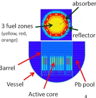
In the first steps of the research activity, the definition of a reference LFR design to be adopted for the development of the computational modules has been carried out. In the ELSY project, two reactor configurations have been studied and characterized, with relevant differences in terms of fuel elements geometry and core composition. One of these options, characterized by hexagonal fuel elements surrounded by a wrapper, can be seen in the sketch reported in Fig. 1, and has then been selected as reference design for the European project LEADER. Several
Ricerca Sistema Elettrico NNFISS – LP3 - 036 Sigla di identificazione Rev. 0 Distrib. L Pag. 5 18 di
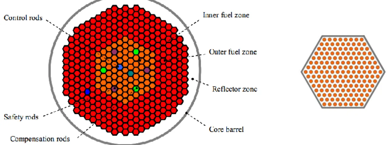
modifications have been introduced, with the intent to scale down the system power and obtain a demonstrator reactor ALFRED (Advanced Lead Fast Reactor European Demonstrator), whose deployment is the main objective of the LEADER project. As a consequence, in the frame of this research activity here described, the reactor design with hexagonal fuel elements has been selected (see Fig. 2).
The systems characteristics have been retrieved from the results of the ELSY project, since no definitive sets of data are available for the design of the LEADER project. The system is characterized by an almost full-scale power (1500 MW-th) and corresponding core dimension and thermal characterization. However, the modelling tool developed can be easily adopted for the analysis of different systems based on the same core geometry and fluid lead flow pattern, and can be fruitfully used for the dynamic analyses of the design of the ALFRED reactor.
2. Modelling for reactor dynamics
The behaviour of a reactor core in steady-state and transient conditions is regulated by the interaction of various phenomena of different origin. The objective of the research carried out in this project has been the simulation of the neutronic and thermal-hydraulic aspects of a lead-cooled reactor, thus including physical effects acting on time-scales that may be extremely different. It is then required to identify the most relevant effects and corresponding time-scales, in order to devise an appropriate solution strategy to be applied in the solution of the multiphysics problem.
In the following sections, the characteristics of the computational tools developed are described. A subsequent section is devoted to the illustrations of some specific aspects of coupled dynamics and to the details on how they are taken into account in the development of the coupled code.
2.1 Neutronic modelling (POLITO)
Ricerca Sistema Elettrico NNFISS – LP3 - 036 Sigla di identificazione Rev. 0 Distrib. L Pag. 6 18 di
The objective of the neutronic computational module is the description of the neutron population in the reactor core. Due to the large dimensionality of the problem, that may involve a large number of hexagonal fuel elements, some starting hypotheses have been introduced.
The modelling of the full-core configurations will be based on a coarse-mesh approach, where the hexagonal fuel element constitutes the starting mesh to be assumed in a
three-dimensional nodal scheme. For this reason, material characteristics have to be homogenized over the element (see Fig. 3), providing few-group constant cross sections that can be used for steady-state and time-dependent evaluations.
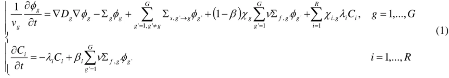
The objective of the development of a multiphysics computational tool requires for an evaluation of the dependence of the material cross-sections on the temperature of the fuel and coolant, in order to take into account the non-linear effects of thermal-hydraulics on neutronics. The modelling of the core will then be based on a multigroup diffusion approach, that can be written in the general form as:
(1)
where all the cross-sections are supposed to be depending on the temperature field within the system.
The time-dependence may be approached in different ways. In order to reduce the computational effort, the implementation of a quasi-static scheme is envisaged, based on the factorization of the multigroup neutron flux as:
(2) where A is the amplitude function, evolving on a fast time-scale, and g is the shape function,
evolving on a slower time-scale. The solution of the time dependent problem is split in the alternate
R i C t C G g C D t v G g g g f i i i i G g g g R i i i g i G g g g f g g g g s g g g g g g ,..., 1 ,..., 1 , 1 1 1 ' ' ' , ' , 1 ' 1 . 1 ' ' ' , ' ' , ) ( ) ; , , ( ) , , , (x y z t g x y z t A t g Fig. 3: Hexagonal fuel element with identification of the cross-section homogenization region (shaded in light blue)
Ricerca Sistema Elettrico NNFISS – LP3 - 036 Sigla di identificazione Rev. 0 Distrib. L Pag. 7 18 di
solution of the two models for amplitude and shape, obtained from the general neutron balance equation by a projection technique. The equation for the amplitude is represented by the well-known point kinetic model
(3)
where the standard definition of the kinetic parameters appearing in the equations (ρ, β and Λ) can be find in [8]. This set of equations needs to be solved on a time-scale in the order of the lifetime of prompt neutrons, i.e p ~ 10-6 s. The modifications of the neutron distributions in the
phase space is taken into account performing updates of the shape function on a longer time-scale, shape, in the order of 10-4 s, but dependent on the transient to be simulated, thus affecting
the values of the kinetic parameters.
In the coupled neutronic-thermal-hydraulic simulation of the reactor core, the value of these parameters are affected by the modification of the neutronic distribution, ψg, which on its
turn is affected by the modification of the material properties as function of the temperature field.
In the frame of the activity performed during this year, the implementation of the neutronic model has been based on the point kinetic model, which assumes g to be constant in time for the
duration of the simulated transient. As a result, the evolution of the amplitude function A(t), after a proper normalization, is representative of the effective thermal power as:
(4) where P(t=0) is the (steady-state) initial power.
The coupling of the neutronic model with the thermal-hydraulic effects is then introduced through the reactivity term, involving temperature coefficients for both the fuel and the coolant. The general form of the reactivity ρ to be inserted into the point model (3) is including both external contributions (modifications of the transport operator due to the introduction of perturbations into the system) and nonlinear feedback effects. If constant feedback coefficients are assumed for both the fuel, f, and coolant, Pb, the reactivity takes the form:
(5) where ρext is associated to the external perturbation, Tfuel is the space-averaged fuel temperature and Tlead the space-averaged coolant temperature. The general formulation of the feedback term involves
coefficients depending on their turn on the temperatures in a general, non-linear, form:
(6)
R i t A t C dt t dC t C t A t dt t dA i i i i R i i i ,..., 1 ) ( ) ( ) ( ) ( ) ( ) ( ) ( 1 ) ( ) 0 ( ) (t P t At P
( ) ,0
( ) ,0
) ( )(t ext t f Tfuel t Tfuel Pb Tlead t Tlead
( ) ,0
( )
( ) ,0
) ( ) ( )(t ext t f Tf Tfuel t Tfuel Pb Tlead Tlead t Tlead
Ricerca Sistema Elettrico NNFISS – LP3 - 036 Sigla di identificazione Rev. 0 Distrib. L Pag. 8 18 di
The variations of the temperatures are considered with respect to “reference” steady-state values, Tfuel,0 and Tlead,0, that are evaluated for the initial configuration. The solution of system (3)
then provides the power evolution in time, according to the normalization in (4). The power is then used as input data for the solution of the thermal-hydraulic problem, as it is explained in the
following section.
2.2 Thermal-hydraulic modelling (POLITO)
The thermal-hydraulic modelling of the full-core three-dimensional system is defined starting from some considerations concerning the main time-scales of the phenomena appearing in the system. The characteristic values of such times can be summarized as follows:
Lead-pin surface coupling Pb-pin ~ 0.1 s
Lead transit time along the fuel element in the axial direction z ~ 1 s
Lead temperature homogenization on a given fuel element cross section hom ~ 1 s, assuming a
uniform fuel temperature among the fuel pins on the same cross section
Heat diffusion through the fuel element wrapper xy ~ 10 s
Pin temperature homogenization on a single pin cross section pin ~ 10 s.
Starting from the general 3D configuration in the full core geometry, on the basis of these hypotheses it is possible to approach the thermal problem as a series of weakly coupled 1D
problems along each fuel element. This approximation is justified by the fact that the heat diffusion through the wrapper is much slower with respect to the lead temperature homogenization time on the x-y section and to the transit time through the core along z (xy >> hom ~ z). As a consequence,
inside each fuel element the coolant temperature TPb(z) is assumed constant on each cross section
(which will be justified for timescales >~ hom). The same assumption can be made for the fuel
temperature Tf(z) = <Tpin(r, z)>, thanks to the relative uniformity of the heat source on each fuel
element section. It must be noticed that, although the temperature at the pin surface Tpin(rpin, z) has
to be equal to the lead temperature TPb(z), due to the fact that Pb-pin << z, the one-dimensional
temperature fields for fuel and coolant will be different (Tf(z) TPb(z)), since the homogenization
time on the pin is much longer than the coolant transit time along the reactor axis (pin >> z ).
The basic model to be considered is referred to the single fuel element, consisting of the following set of coupled equations:
1D mass balance (7) 1D momentum balance (8) 1D energy balance (9) cos 1 g Fv z p z v v t v z z z z F v A Q z A A v c z T k z z p v z v c t p z z s Pb z z s 2 2 ' F v A Q z A A v T c z T k z z v T pc z T v c t T c z z Pb v Pb z Pb v Pb z v Pb v '
Ricerca Sistema Elettrico NNFISS – LP3 - 036 Sigla di identificazione Rev. 0 Distrib. L Pag. 9 18 di
containing the lead pressure p (z, t), velocity vz(z, t) and temperature T (z, t), coupled to the Pb
1D heat conduction model for the fuel temperature Tf(z, t)
(10)
The parameters appearing in Eqs. (7-10) are:
A is the lead cross section
cf is the fuel specific heat
cs is the sound speed in lead
cv is the lead specific heat at constant volume
F is a coefficients accounting for friction effects, defined as
(11)
where f is the friction factor and Dh is the hydraulic diameter
g is the gravity acceleration
H is the lead-pin surface heat transfer coefficient
k is the thermal conductivity for lead and kf for the fuel
p is the lead pressure
F is the interface perimeter between lead and fuel
Q’ is the linear heat flux exchanged between the pins and the coolant
Qf is the linear power generation inside the fuel
γ is the angle between z and vertical direction to take into account buoyancy
Φ is Gruneisen parameter, defined as:
(12) where s is the entropy.
The set of 1D differential equations (7-10) is solved at each time step for each fuel assembly. Then the thermal coupling between neighboring assemblies is computed in explicit taking into account wrapper thermal resistance, thus realizing the horizontal 2D coupling.
The thermophysical properties of lead adopted for the calculations have been retrieved from Ref. [9]. Validation with respect to experimental programs currently under-way or envisaged in the next future would be advisable [10].
The fuel thermophysical properties adopted are characteristic for a UO2-based fuel, taken from
Ref. [11]. It must be pointed out that, although the current design for LFR are usually considering a
f f Pb f f f f f f f f A Q T T A H z T k z t T c h z D v f F 2 s T T Ricerca Sistema Elettrico NNFISS – LP3 - 036 Sigla di identificazione Rev. 0 Distrib. L Pag. 10 18 di
nuclear fuel composed of mixed oxides (MOX), the thermal data required for the present modelling are available only for Uranium oxide-based fuel.
The friction factor for lead and the heat transfer coefficient between the pins and the coolant are taken from correlations reported in Ref. [12] (results of these correlations agree within 10% with those of Ref. [10]).
The solution of the set of equations (7-10) requires the heat source term produced by the fission events. This term, Qf, constitutes the coupling term for the thermal-hydraulic model with the
neutronic equations, in the form:
Qf = Af Ef Σf (13)
where Ef is the energy released per fission, Σf is the macroscopic fission cross section and is the
neutron flux, obtained from the neutronic model (1).
In the frame of the modelization developed during this year activity, the power produced by fission is represented by the average power for the fuel element, according to the point model (2). As a consequence, the spatial distribution along the reactor axis is not readily available for the thermal model, for which the linear power density is needed. To this purpose, the power obtained in the frame of point kinetics has been distributed according to a cosine shape for the z variable, preserving the full power level. This distribution represents a physically reasonable assumption for the fission production in this kind of systems, where no relevant density effect on the coolant are experienced and thus the axial form of the flux is not relevantly distorted by the temperature gradient.
Correspondingly, the space-averaged temperatures (Tfuel and Tlead) to be fed into the neutronic
code through the reactivity term (5-6) are obtained by an axial integration of the temperature distribution Tf(z) and TPb(z).
2.3 The principles of coupled dynamics (POLITO)
The computational tool is composed by two main modules, dealing with the neutronics (NE) and the thermal-hydraulics (TH) of the systems, respectively, as described in the previous sections. They have been developed as separate, stand-alone, FORTRAN codes, and have been tested for consistency and accurateness separately. As a following step, suitable procedures for the data exchange have been put into place.
As mentioned previously, the coupled dynamics of lead cooled reactor described by the computational tool here developed is characterized by the interaction of neutronics and lead thermal-hydraulics, through some specific effects:
- the neutronic calculations provide the fission production within the system, constituting the heat source Q for the thermal calculations;
- the fluid-dynamic calculations generate the temperature fields in the fuel and coolant, which are affecting the reactivity of the systems via the temperature coefficients.
The exchange of these data is obtained through the TISC commercial platform, allowing the synchronization of execution and in/out exchange of separate codes. This strategy, which has
Ricerca Sistema Elettrico NNFISS – LP3 - 036 Sigla di identificazione Rev. 0 Distrib. L Pag. 11 18 di
already been tested for different applications [13], works very well and allows each module to adopt the most suitable time stepping strategy, taking into account the respective time-scales.
At this point, the aspects connected to the choice of the time step for the execution of the two different codes and the input exchange need to be analyzed. The physical phenomena involved in the reactor dynamics are characterized by a large spectrum of different time-scales; however, it can be stated that the neutronic phenomena are generally evolving on a much faster scale, at least for what concerns the behaviour of prompt neutrons (delayed neutron precursors evolve on scales in the order of several seconds). Therefore, the neutronic module, and specifically the point kinetic system (2), will be solved on the scale of prompt neutrons p. As a second step, if the update of the neutron
distribution is required, this can be performed on their proper time-scale, shape. It must be noted that
all these times are much shorter that the fastest thermal-hydraulic time-scale. As a consequence, it is possible to couple the neutronic and the thermal-hydraulic modules explicitly, alternating their solution on the fastest thermal time-scale. This is done using the TISC platform, which calls each module in turn, exchanging at each defined time step the needed information (Tfuel and TPb from TH
to NE, Qfuel from NE to TH).
2.4 Feedback coefficients (ENEA - POLITO)
The simulation of the neutronic behaviour of the reactor, coupled to the thermal-hydraulic effects, is based on the evaluation of how the characteristics of the materials composing the core are affected by the temperature and pressure fields. This results, in general terms, requires the
determination of the temperature-dependent macroscopic cross sections for the system and the consequent calculation of the neutron population at equilibrium. This procedure is by default iterative, since the temperature field is determined by the heat source, established on its turn by the fission production. Thus, in the general case, when a full-space model for neutronics is coupled to a spatial thermal-hydraulic code, the steady-state configuration of the system needs to be evaluated by successive iterations, towards an equilibrium state, depending on the system configuration analyzed. The problem solved in the frame of this year activity is slightly different, being based on a point kinetic approach for the neutronic evaluations. The definition of a “reference” power level, to be intended as the power level for the stable operation of the reactor, when no perturbations are introduced, constitutes the input data for the thermal model to evaluate the temperature field. Once a space-averaged value for the fuel and coolant temperature is obtained, this is set to be the
“reference” value, identified with subscript “0”, that will be inserted into the expression (5). It is clear at this point that, if no perturbations are introduced into the system, the system will operate at the same power and with the same temperatures indefinitely, thus requiring for no iterations to reach convergence. The dynamic behaviour is then induced whenever a perturbation is introduced into the reactor (ρpert or changes in the thermal conditions). The flowchart of the procedure adopted is
presented in Fig. 4.
The neutronic response to thermal feedback is here modelled with a lumped parameter relation, depending on the feedback coefficients αf and αPb. These values can be assumed as constant (see Eq.
(5)), or depending on their turn on the temperature (Eq. (6)), but the solution strategy is not modified in both cases. The additional complication associated to the temperature-dependent coefficients lies in the necessity to interpolate the values with respect to tabulated data at constant temperature intervals.
Ricerca Sistema Elettrico NNFISS – LP3 - 036 Sigla di identificazione Rev. 0 Distrib. L Pag. 12 18 di Initial power definition TH solution Temperature averaging Time t = 0 perturbation NE solution between t and t+Δt (with
a fine time-mesh) TH solution between t and t+Δt Steady-state Transient P0, Tinlet,, vinlet
Fig. 4: Flowchart of the computational scheme adopted for the coupled simulation.
3. Results
In these sections, the results of the calculations performed with the coupled code are presented. The objective of these calculations has been the validation of the coupling procedure, involving the use of the TISC platform, as well as the prediction capability and reliability of the results obtained by the thermal-hydraulic calculations when coupled to the neutronic evaluation.
3.1 Input data for the calculations (POLITO - ENEA)
The configuration of the system analyzed has been chosen on the basis of the modelling carried out, based on the point kinetic approach. Such modelization, describing the reactor core as a single point, is equivalent to the evaluation of the neutronic population in a single fuel element surrounded by an infinite lattice of identical fuel elements. As a consequence, the corresponding modelization
Ricerca Sistema Elettrico NNFISS – LP3 - 036 Sigla di identificazione Rev. 0 Distrib. L Pag. 13 18 di
for the thermal part has been carried out under the same hypothesis, resulting in adiabatic boundary conditions at the wrapper level in the radial direction. This configuration, although simplified, is useful to different purposes:
- for the testing of the numerical procedure of coupling of the codes;
- for the performance of physical evaluations that are significant for the system under consideration.
The problem to be solved by the thermal-hydraulic module is thus the solution of the set of
equations (7-12) for a single channel, providing the fuel and coolant temperature as function of the axial variable and time. As stated before, the power distribution along the channel has been
generated according to a cosine shape, which is physically consistent for the problem at hand. The numerical values of the reactor data that have been adopted for the calculations have been retrieved starting from the available information on the reactor design exploited in the ELSY project. The full reactor power has been divided by the number of fuel elements to obtain an average power associated to the single element, and the thermal characteristics of the lead at the inlet have been taken as for the ELSY design:
“reference” power level Ptot,0 = 1500 MWth;
number of fuel elements NFE = 433;
power/fuel element P0 = 3.5 MWth;
Linear power distribution, deposited totally into the fuel: axial sinusoidal shape (preserving the integral): z H H P z p sin 2 ) ( 0 0
where the active core height is H = 120 cm
Inlet lead temperature TPb,in = 673 K;
Pressure drop across the core Δp = 0.135 MPa, leading to a lead fuel velocity vPb ~ 1 m/s;
Geometrical data of the fuel element, necessary in order to evaluate fuel wetted perimeter and coolant and fuel cross sections.
The simulations of time-dependent configurations for the reactor require for the data neutronically characterizing the reactor core, i.e. the kinetic parameters, delayed neutron data and feedback coefficients. These data have been partially obtained from the ELSY data:
Prompt neutron mean lifetime Λ = 1e-5 s;
Constant reactivity coefficients according to formulation (5): fuel = 0.8 pcm/K and Pb
= + 0.35 pcm/K;
while the data for the delayed neutron families and more general relations for the value of the system reactivity as a function of fuel and coolant temperatures were not readily available (required for the formulation (6) of the feedback term).
The missing data have been retrieved starting from a reactor configuration that has been studied in previous research activities in collaboration between ENEA and Politecnico di Torino [14]. The system in this case was subcritical, but with the same range of temperature, similar nuclear fuel composition (MOX fuel) and fast neutron spectrum. It is then physically consistent to adopt the delayed precursors data identified in that framework for the present work, as summarized in Table %1.
Ricerca Sistema Elettrico NNFISS – LP3 - 036 Sigla di identificazione Rev. 0 Distrib. L Pag. 14 18 di
Table %1: Delayed neutron precursor families data.
λi [s-1] 0.0129 0.0313 0.1346 0.3443 1.3764 3.7425
βi [pcm] 9 74 67 129 59 19
β [pcm] 356
A different approach to coupled dynamics can be adopted, introducing
temperature-dependent feedback coefficient. This option is more closely related to the real physical behaviour, since the correlation between temperature and reactivity is usually not linear (as assumed in the case of constant α’s). The generation of the input data in this case requires the evaluation of the system reactivity for a set of temperatures for the fuel and the coolant, to be used as database for the interpolation at the actual values of Tf and TPb during the calculations. Such calculations take into
account all the effects of temperature on the material properties of the fuel and the coolant, including both nuclear effects (e.g., Doppler broadening) and the thermal expansion coefficients.
The set of data adopted have been obtained, again, from the design mentioned above, whose characteristics in terms of material composition and influence of the thermal expansion are very close to the lead-cooled reactor design.
In the following sections the results obtained from some calculations are presented, starting from the evaluation of the steady state configuration, and thus confirming the significativity of the starting hypothesis. Results for transient situations and some stability analyses are then performed.
3.2 Transient evaluations (POLITO)
The calculation of the steady-state configuration of the system, starting from the set of data previously described, has given the temperature profile for fuel and coolant. It can be noticed that the value of the lead coolant at the outlet of the is in good agreement with the design value of ELSY; thus supporting the consistency and relevance of the model under consideration.
Time-dependent calculations have been performed, introducing perturbations in the reference configurations that can be representative of operational and accidental transients in this kind of system [15-16].
As a first test, a step reactivity of 100 pcm is inserted at time t = 0; this could correspond to, e.g., the sudden ejection of a control rod. The system behaviour has been simulated assuming all the input data described above, in conjunction with constant feedback reactivity coefficients. The evolution of reactivity, power, maximum temperatures of lead and fuel (TPbmax and Tfuelmax)
following the reactivity insertion is reported in Fig. 5. The total reactivity of the system is brought back to zero by the effect of the negative feedback, which is compensating the external
perturbation. For this type of configuration the system is therefore proven to be stable. The verification of stability is necessary in view of the fact that the temperature coefficient of the coolant is positive, although smaller in absolute value with respect to the fuel temperature coefficient. The stability follows from the combined temperature effects of fuel and coolant. The figure also confirms that, at least in this case, the maximum temperature of fuel and coolant remain well below the fuel melting temperature (Tmelt ~ 3120 K, for UO2) and the coolant boiling
Ricerca Sistema Elettrico NNFISS – LP3 - 036 Sigla di identificazione Rev. 0 Distrib. L Pag. 15 18 di
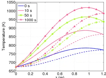
The evolution of the spatial distribution of TPb and Tfuel is shown in Fig. 6. We notice the more
symmetric profile of Tfuel responding directly to the cosine-distributed power input, while the more
asymmetric profile of TPb is related to the advection in the lead coolant.
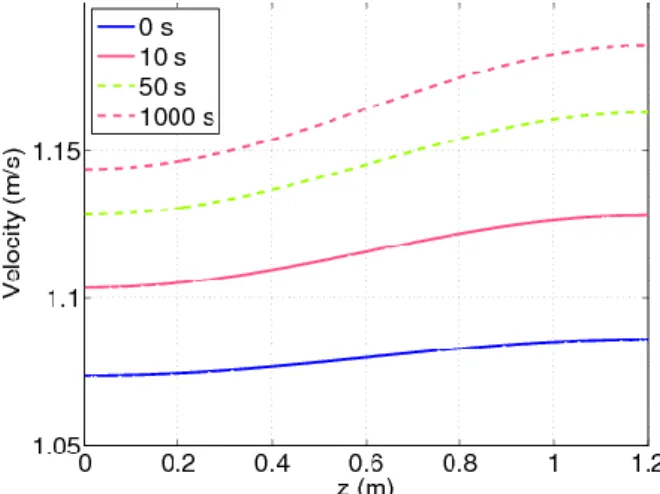
The evolution of the spatial distribution of the lead flow speed vPb is shown in Fig. 7. A higher
value of Qfuel leads to higher temperatures, therefore to lower values of the coolant density and
impedance, which for a given Δp gives a higher velocity vPb. As the TPb increases (and the Pb
density decreases) the flow accelerates along the channel, in order to maintain the constant mass flow rate.
Fig. 5. Evolution of total reactivity (perturbation + feedback), power and maximum temperatures for a transient induced by a 100 pcm reactivity insertion (constant reactivity
coefficients).
Fig. 6: Axial distribution of fuel and lead temperatures as a response to a 100 pcm reactivity insertion (constant reactivity coefficients).
Ricerca Sistema Elettrico NNFISS – LP3 - 036 Sigla di identificazione Rev. 0 Distrib. L Pag. 16 18 di
Finally, we perform a study of the sensitivity of the predictions of the model to the value of
fuel, which is a crucial parameter for the dynamic simulation. This might be of interest, e.g., while
defining the Pu content in the MOX fuel; indeed, fuel may increase with increasing Pu content, due
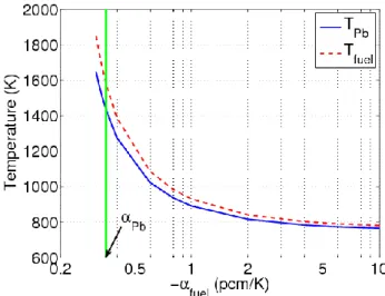
to the fission resonances. Table %2 summarizes the results of the sensitivity study. As expected, it is seen that if fuel is larger than a certain threshold value *, the 100 pcm reactivity insertion leads to
instability. The reason why * > Pb is that only the fuel is heated, therefore the reactivity
becomes more sensitive to a temperature increase of the fuel than of the coolant. For values of fuel
< *, the system goes through a transition region which is however still unacceptable, because
TPbmax increases above Tboil, as can be seen in Fig. 8.
Table %2: Parametric study on the fuel temperature feedback coefficient, corresponding to the 100 pcm reactivity insertion transient.
Behavior
increasing ρ = unstable decreasing ρ, Pb boiling Stable
fuel (pcm/K) -0.3 -0.2
Ricerca Sistema Elettrico NNFISS – LP3 - 036 Sigla di identificazione Rev. 0 Distrib. L Pag. 17 18 di
References
[1] US DOE Nuclear Energy Research Advisory Committee and the Generation IV International Forum, A technology roadmap for Generation IV nuclear energy systems, DOE, Washington (2002).
[2] Neutron Transport and Thermal-Hydraulics Methods Development for the CASL Modeling and Simulation Hub, Roundtable, sponsored by MCD, Session Organizer and Chair: Anil Prinja, ANS
Winter Meeting, Las Vegas (2010).
[3] V.V. Orlov et al., Fuel cycle of BREST reactors. Solution of the radwaste and non-proliferation problems, International Conference ICONE-11, Tokyo (2003).
[4] Liquid metal cooled reactors: experience in design and operation, IAEA-TECDOC 1569, IAEA, Vienna (2007).
[5] L. Cinotti et al., the ELSY Project, International Conference on the Physics of Reactors, Interlaken (2008).
[6] Liquid metal cooled reactors: experience in design and operation, IAEA-TECDOC 1569, IAEA, Vienna (2007).
[7] F. Roelofs, B. de Jager, A. Class, H. Jeanmart, P. Schuurmans, A. Ciampichetti, G. Gerbeth, R. Stieglitz, C. Fazio, European research on HLM thermal-hydraulics for ADS applications, Journal of
Nuclear Materials, 376, 401-404 (2008).
[8] Z. Akcasu, G.S. Lellouche, L.M. Shotkin, Mathematical methods in nuclear reactor dynamics, Academic Press, New York (1971).
[9] Handbook on Lead-Bismuth Eutectic Alloy and Lead Properties, Materials, Compatibility, Thermal-hydraulics and Technologies, OECD-NEA, Paris (2007).
[10] G. Bandini et al., CIRCE experimental set-up design and test matrix definition, ENEA Report
IT-F-S-001 (2011).
[11] S. G. Popov, J. J. Carbajo, V. K. Ivanov, G. L. Yoder, Thermophysical Properties of MOX and UO2 Fuels Including the Effects of Irradiation, ORNL Report TM-2000/351, ORNL (2000).
Fig. 8. Maximum fuel and coolant temperatures as a function of the value of the fuel temperature coefficient.
Ricerca Sistema Elettrico NNFISS – LP3 - 036 Sigla di identificazione Rev. 0 Distrib. L Pag. 18 18 di
[12] N. E. Todreas, M. S. Kazimi, Nuclear Systems, 1, Hemisphere, New York (1993).
[13] L. Savoldi Richard, F. Casella, B. Fiori, R. Zanino, The 4C Code for the Cryogenic Circuit Conductor and Coil modeling in ITER, Cryogenics, 50, 167 (2010).
[14] ANSALDO Nucleare, “Energy Amplifier Demonstration Facility Reference Configuration”, ANSALDO Report EA-B0.00-1-200 – Rev. 0, January 2009.
[15] R. Bonifetto, S. Dulla, P. Ravetto, L. Savoldi Richard, R. Zanino, Progress in multi-physics modeling of innovative lead-cooled fast reactors, International conference ICENES 2011, San Francisco, 2011.
[16] R. Bonifetto, S. Dulla, P. Ravetto, L. Savoldi Richard, R. Zanino, Multi-physics modeling of innovative lead-cooled fast reactors, UIT conference, Torino, 2011.