UNIVERSITY OF SALERNO
FACULTY OF MATHEMATICAL,PHYSICAL AND NATURAL SCIENCES DEPARTMENT OF PHYSICS “E.R:CAIANIELLO”
D
OCTORALT
HESISI
MAGE
P
ROCESSING
T
ECHNIQUES
FOR
M
IXED
R
EALITY AND
B
IOMETRY
Advisor: Author:
Prof. Andrea F. Abate Dott. Stefano Ricciardi
Coordinator:
Prof. Roberto Scarpa
A thesis submitted in fulfilment of the requirements for the degree of Doctor of Philosophy
in
SCIENCES AND TECHNOLOGIES OF INFORMATION,COMPLEX SYSTEMS AND ENVIRONMENT
“Science is a way of thinking much more than it is a body of knowledge”.
SUMMARY
Abstract………..…5
1. Introduction………..…7
2. Advanced Interaction and Visualization Methods for Mixed Reality... ………..….10
2.1. Finger Based Interaction for AR Environments…..………..…11
2.1.1. Overarall system architecture………13
2.1.2. Mixed reality engine ………14
2.1.3. Finger based contact-less interface………18
2.1.4. Experiments and comments to the results……….………21
2.2. Diminished Reality, Techniques and Applications…………...………26
2.2.1. Selective removal of equipment features………..…………27
2.2.2. A WYSIWYN approach to objects augmentation………29
2.3. Handling Occlusions While Interacting In Mixed Reality Environments”...…36
2.3.1. The approach at a glance………...…39
2.3.2. Method description………40
2.3.3. Experimental results………..…43
2.4. Visual Interaction in Mixed Reality by Means of Gestures ………….………46
2.4.1. Gesture recognition by means of multiple sensors………49
2.4.3. Implementing the MR operating environment……….……56
2.4.4. An application to medical imaging……….………..……59
2.4.5. A user evaluation study……….……62
3. Biometrics for Ambient Intelligence Environments ………...………….….…70
3.1. Main approaches to 3D face recognition………...……71
3.2. Face Technical Issues ………...………72
3.3. Face Signature by Normal Map……….…………77
3.4. A Biometrics-empowered Ambient Intelligence Environment………..………85
3.5. Experimental Results……….……86
Abstract
This thesis work is focused on two applicative fields of image processing research, which, for different reasons, have become particularly active in the last decade: Mixed Reality and Biometry. Though the image processing techniques involved in these two research areas are often different, they share the key objective of recognizing salient features typically captured through imaging devices.
Enabling technologies for augmented/mixed reality have been improved and refined throughout the last years and more recently they seems to have finally passed the demo stage to becoming ready for practical industrial and commercial applications. To this regard, a crucial role will likely be played by the new generation of smartphones and tablets, equipped with an arsenal of sensors connections and enough processing power for becoming the most portable and affordable AR platform ever. Within this context, techniques like gesture recognition by means of simple, light and robust capturing hardware and advanced computer vision techniques may play an important role in providing a natural and robust way to control software applications and to enhance on-the-field operational capabilities. The research described in this thesis is targeted toward advanced visualization and interaction strategies aimed to improve the operative range and robustness of mixed reality applications, particularly for demanding industrial environments.
Biometric recognition refers to the use of distinctive physiological and behavioural characteristics, called biometric identifiers, for automatically recognizing individuals. Being hard to misplace, forge, or share, biometric identifiers are considered more reliable for person recognition than traditional token or knowledge-based methods. Others typical objectives of biometric recognition are user convenience (e.g., service access without a Personal Identification Number), better security (e.g., difficult to forge access). All these reasons make biometrics very suited for Ambient Intelligence applications, and this is especially true for the user’s face that is one of the most
common methods of recognition that humans use in their visual interactions. Moreover, face features allow to recognize the user in a non-intrusive way without any physical contact with the sensor. To this regard, the second part of this thesis, presents a face recognition method based on 3D features to verify the identity of subjects accessing the controlled Ambient Intelligence Environment and to customize all the services accordingly. In other words, the purpose is to add a social dimension to man-machine communication thus contributing to make such environments more attractive to the human user.
Chapter 1
Introduction
Today, we live in a image-centric world in which visual communication and comprehension represent crucial ways to interact and learn at any level. The power of images has never been so tangible and valuable in every human activity. Consequently, the interest of scientific research in every aspect of this form of knowledge has never been so strong. The digital revolution has made possible measuring, sampling, processing and even sinthetizing images captured through a new breed of devices almost impossible to imagine a few decades ago, whose tecnological evolution does not know pauses and is itself a stimulus for further development and research in a seamless loop. Computer scientists have the privilege of being at the center of this revolution and research areas such as image processing and image synthesis are constantly pushing the boundary of available technology, with huge effects on the mass-market and on industrial applications as well.
In this context, Mixed/Augmented Reality is emerging from a long period of unfulfilled promises as the related enabling technologies are finally mature enough to unleash the potential of combining computer generated visual contents with the actual enviroment around the user. As the impact of this technology on the everyday life is possibly huge, there is a clear need for addressing the main open challenges that currently still limit its usage, particularly in demanding environments and applications.
On another front of the image related research, the outstanding technological progress that has characterized the development and the pervasive diffusion of high-definition low-noise image sensors, put the basis for ubiquitous biometric applications almost unfeasible in the near past. About twelve years after September 11th 2001, the diffusion of person identification and verification systems has reached a worldwide dimension, as anyone travelling overseas has probably experimented while waiting in a
queue for immigration control procedures. As most biometric systems (face, iris, fingerprint, ear, etc. ) rely on image capture and processing to extract and compare user’s biometric traits, the worldwide availability of high-performance ubiquitous image capture devices (smartphones, tablet, etc.) is opening the horizon for a new generation of applications.
This thesis, tries to provide a glimpse of these new application fields, focusing on applying techniques of image processing in both the 2D and 3D domains for Mixed Reality and Biometry contexts. The topics covered hereafter, could probably not be considered “mainstream”, though they concern aspects which might well have a great impact on the usability of the aforementioned techologies. More in detail, the study presented in the following pages is organized as follows:
• Chapter 2 is dedicated to Mixed Reality topics as detailed below
o Section 2.1 describes a comprehensive proposal for a mixed reality environment, providing powerful interaction capability with the co-registered virtual/real objects by means of a not-instrumented finger based interface to improving the effectiveness of computer assisted training procedures in mission critical systems,
o Section 2.2 addresses the topic of “diminished reality”. Besides the usual augmenting paradigm common in mixed reality, the proposed approach enables a diminishing visualization strategy allowing the user to see only the fraction of the real object/environment that is visually relevant for the task to be performed.
o Section 2.3 deals with the occlusion problem related to hand-based interaction in mixed reality. The method described, enables the composition of the virtual objects onto the real background to be performed respecting the distance of each rendered pixel according to the user viewpoint.
o Section 2.4 presents a context adaptive head-up interface, which is projected in the central region of the user’s visual field and exploiting gesture based interaction to enable easy, robust and powerful manipulation of the virtual contents which are visualized after being mapped onto the real environment surrounding the user.
• Chapter 3 is dedicated to Biometry and it describes in Section 3.1 a comprehensive face recognition framework based on 3D features to verify the identity of subjects accessing an Ambient Intelligence Environment and to customize all the services accordingly. The face descriptor is based on normal map to enabling fast probe-gallery matching yet it is robust to facial expressions and facial hair by means of specific weighting maps.
Chapter 2
Advanced Interaction and Visualization Methods for
Mixed Reality
Over the last decade Augmented/Mixed Reality (AR/MR) technology has become more and more diffused and affordable, dramatically expanding the applicative horizon across fields ranging from aerospace to automotive, from surgery to marketing, proving that the mix between real and virtual has a huge potential for the big enterprise and the mass market as well. The last years in particular, have seen a growing hype about Augmented/Mixed Reality pushed by announcements of new dedicated devices like the Google Glass, just to mention the most known, claiming the ability to augment the vision field with context dependent contents, eventually co-registered to the real world.
It is clear enough that these technologies, apart from technical limitations still concerning tracking accuracy/robustness, or field-of-view wideness, really have a great potential for a broad range of applicative fields and particularly for multimedia training and learning which could finally move from the computer space to the real world.
The growth experimented so far has been stimulated by different factors: a dramatic increase of both general and visual computing power of any kind of computer, a general cost reduction of AR specific devices, like see-trough Head Mounted Displays and motion tracking systems and, last but not the least, the new generations of smartphones, equipped with an arsenal of sensors (hi-res cameras, gyroscopes, accelerometers, GPS, electronic compass, etc.) and enough processing power to became the most portable and affordable AR platform ever. Within this exciting scenario, the research effort should be focused not only on new approaches to the main AR topics (more accurate tracking in outdoor applications, better and lighter hi-res HMD, etc.) but also on open and new challenges as well. The following subsections of this thesis deal with some of these last kind of research topics, and particularly they concern not-instrumented finger-based interface in a MR environment (Section 2.1), diminished reality (Section 2.2), occlusion
handling (Section 2.3) and advanced gesture-based interaction (Section 2.4), also trying to stress the proposed approaches in demanding application contexts.
2.1 Finger Based Interaction for Demanding AR Environments
Mixed Reality technologies often reveal serious limitations when applied to challenging application environments. For these particular context, indeed, specific requirements in terms of tracking accuracy and coverage, augmentation strategies and interaction capabilities determine whether a mixed reality application is useful or not. Mission critical installations such as military and civil radar systems, navigation systems aboard ships and airplanes, high performance communication systems based in airports, ports and oil rigs are just a few examples of high-tech environments featuring an ever growing range of complex hardware and software components. In case of break down of one of these components, it is of paramount importance that the faulty part is repaired as quickly as possible, as the security of a large number of people may be at risk. In this context, the latest advances of Mixed Reality (MR) technologies [1] may prove really useful in assisting on-site operators during servicing and repair activity. Most of on-site interventions in this field depend on trained personnel applying established procedures to complex equipment in relatively static and predictable environments. These procedures are typically organized into well-defined sequences of tasks, concerning specific items in specific locations. A fundamental aspect to be considered is represented by the interaction level available and the related interaction paradigm. The user, indeed, should be able to select what kind of augmenting content to display according to his/her needs by interacting with the MR environment without complicated gear. This section describes a not-instrumented finger based interface to provide effective and reliable visual aid during maintenance operations. This interface has been designed and tested as a part of a comprehensive MR environment aimed to support servicing and repair operations in mission critical systems, but that could be suited to other demanding contexts as well. The proposed architecture is based on a multiple marker-based tracking, and it has been tested in a radar control training facility to assess its benefits and limitations in a real scenario.
Scientific literature presents a number of studies covering the topic of mixed/augmented reality applied to industrial contexts. In 2002, the project ARVIKA [2] fostered the research and the development of AR technologies for production and service in the automotive and aerospace industries, for power/process plants, for machine tools and production gear. Klinker et al. [3] presented an AR system for the inspection of power plants at Framatome ANP, while Shimoda et al. [4] presented an AR solution in order to improve efficiency in nuclear power plants (NPP) maintenance interventions and to reduce the risk of human error. Mendez et al. [5] developed a virtual (AR based) filter to reveal hidden information that is behind an occluding object, to enhance data of interest or to suppress distracting information. Pentenrieder et al. [6] showed how to use AR in automotive design and manufacturing, to analyse interfering edges, plan production lines and workshops, compare variance and verify parts. Still et al. [7] proposed an augmented reality system for aiding field workers of utility companies in outdoor tasks such as maintenance, planning or surveying of underground infrastructure, exploiting geographical information system.
More recently, De Crescenzio et al. [8] described AR based interfaces as valuable tools in preventing manufacture errors in the aviation field. Whatever the context considered, tracking precisely and reliably the user point of view (POV) with respect to six degrees of freedom is of paramount importance for co-registering virtual objects with the surrounding environment. Over the years different technologies have been proposed for this purpose (magnetic, ultrasonic, inertial, computer vision based, hybrid, etc.), each with advantages and disadvantage. However, to this date, none of them can be considered as a general solution, whereas each approach can be suited to a particular domain (indoor/outdoor usage, small/wide/scalable operating volume, presence/absence of ferromagnetic materials or electromagnetic fields, etc.).
Computer vision, in both the marker-based [9] [4] and marker-less [10] [11] variants, is generally recognized as the only tracking methodology that has the potential to yield non-invasive, accurate and low cost co-registration between virtual and real [12]. As the MR interface described in the following pages should be able to working on equipment rich of small components and operating in the vicinity of strong electromagnetic fields, the choice of a multi-marker tracking method seems adequate to
deliver high accuracy and robustness. This last scenario also highlights the relevance of a proper interaction capability within the augmented environment, which could not be properly addressed by conventional input device like mouse and keyboard, as the user usually stands upright, eventually moving. Wei et al. [13] introduced a MR framework featuring voice commands, but a hand-based interface would rather be more suited to the scope. As a hardware solution (instrumented gloves plus wrists tracking) would provide accurate hands capturing but would also reduce system’s acceptability, a more feasible option is to exploit image-based techniques to track hands in real time [14]. The simple and robust approach described hereafter is based on the recent work by Mistry and Maes [15] and rely on colored caps worn on index and thumb fingers to track their position and gestures, providing effective and natural interaction within the MR environment. A final aspect to be considered is the computing/visualization hardware required by the system to operate. The growing diffusion of new-generation smartphones/tablets promise to deliver cheaper and more usable [16] AR platforms [17]. This is probably true if the interaction is always mediated by the touch-screen, but when the interaction also implies a contact with physical environment, the user is forced to hold the device with one hand while operating with the other hand behind the device’s screen. If this is the case, a prolonged working session is likely to become a stressful experience. For this main reason a video see-through HMD and a backpack enclosed notebook has been preferred over a tablet computer.
2.1.1. Overall system architecture
The system proposed is schematically depicted in Figure 1. It is composed by three main components. The Mixed Reality Engine (MRE) is in charge of user’s head tracking, scene augmentation/rendering and servicing procedures management. The User-System Interface captures fingers position/gestures enabling the human-computer interaction, while the Maintenance Database contains the working environment setup, the virtual contents and the maintenance procedures required for the system to work. To start the assisted servicing procedure, the user has to wear a video-based see-through HMD, a backpack enclosed notebook and a few fingertips caps required for contactless interaction. This architecture is further detailed in the following subsections.
2.1.2. Mixed reality engine
As mentioned in the previous sections, the tracking system developed exploits optical markers for estimating user’s perspective. It is based on the well-known ARToolkit open source AR library [18] by implementing new functions and designing a marker configuration optimized for the application context considered. Typical marker based tracking systems operating under controlled conditions (i.e. avoiding or at least reducing strong reflections, extreme shadows and excessive camera noise) are able to track the user’s point of view provided that the head mounted camera entirely frames a single marker.
Figure 1: The overall schematic view of the system.
MR Engine User-System interaction GUI Database HMD Camera Fingers Tracking Video stream Gesture recognition Service procedures Diminishing Augmenting Augmentation strategy Or Or environmentWorking Virtual contents Video stream HMD Display Co-registration Service procedure manager Rendering Video stream
This simple solution, often adopted for desktop based AR applications, forces the user to continuously aim at the marker, holding it in the center of the visual field to reduce the risk of detection miss. Moreover, this configuration often involves the need to use large markers (10x10 cm. or more is fairly common), because the accuracy of user’s tracking directly depends on precise estimate of marker’s apparent position/orientation that, in turn, is affected by the amount of error in measuring marker geometrical features, which are proportionally easier to detect on a larger pixel surface. On the other side, arranging a large marker in the middle of operational environment could simply be unfeasible for many application contexts characterized by uneven surfaces or it could even interfere with the operations.
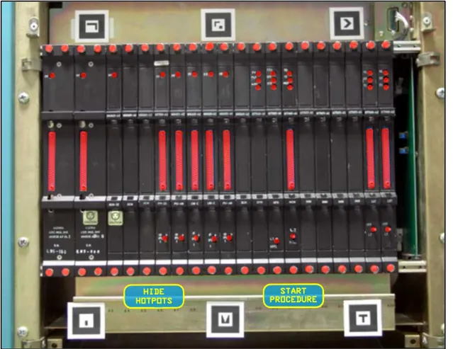
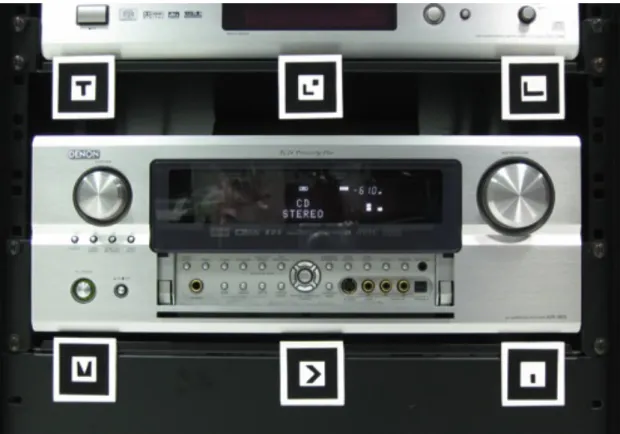
In this study, many of these issues are addressed by exploiting multiple markers, thus delivering an inherently more robust and more accurate tracking even using small markers. Factors like the average distance between user and augmented object, required tracking volume, camera’s focal length and resolution, have to be carefully considered when designing the marker configuration as many of them depend on the particular operating environment. In our test-bed, a set of six 4x4 cm sized markers (see Figure 2) provides an optimal tracking coverage of approximately 60x60x60 cm with an equivalent co-registration error within 2 mm, which is below the size of most small parts. As the relative position of each marker with respect to the absolute reference system is known, when more than one marker is recognized each approximated estimate of camera’s position/orientation (relative to a particular marker) contributes in reducing the overall co-registration error through a weighted average strategy based on the quality and number of visual features recognized (see Figure 3). To this regard it has to be remarked that the rotational component of camera tracking has a greater impact on augmentation accuracy compared to the positional component. In fact, even a degree of error may produce a visible misalignment between virtual-to-real as the distance from the tracked point increases. To minimize this effect the origin of absolute reference system (respect to which is expressed the position of any virtual content) is deliberately located in the geometric center of the marker-set to further reduce the rotation co-registration error of all objects falling within it.
Figure 2: The full marker set and all the available hotspots highlighted after successful
co-registration calibration.
Additionally, to reduce unwanted camera shaking tracking data was smoothed out by means of a damping function. The marker set is easily scalable. For instance, by adding other six markers (arranged in two strips of three, placed 60 cm. above and below the basic set) an optimal tracking volume of 180x60x60 cm (adequate for a full-size industrial rack) is seamlessly achieved. Besides an embedded calibration function aimed to measure and correct camera’s lens distortion, a manual procedure allows the user to fine-tune co-registration between the real camera and its virtual counterpart in charge of rendering the required graphics.
Each of the six degree of freedom plus the camera’s focal length and markers’ thresholding can be precisely adjusted. This task is performed only once unless physical or environmental changes occur in equipment’s configuration.
The hierarchical representation adopted provides an increasingly detailed description while proceeding from the highest to the lowest level. An environment description file, indeed, contains the precise positioning of any relevant equipment (e.g. a system rack) including all the associated items (e.g. the boards located within the rack) by means of specific tags. In a similar way, for any item, an object description file contains a tag list of all the hotspots associated to it (e.g. switches, screws, warning lights, connectors, etc.). The MR engine, according to the aforementioned descriptors, builds up a virtual scene by means of a DOM XML parser, while another XML based language, Xpath, is used to query the application database to retrieve the required data. The MR engine also performs another crucial task: the maintenance procedure management. Each generic maintenance procedure can be represented as a deterministic finite automaton (DFA). According to this approach, a particular state represents a maintenance step and its links define the execution order.
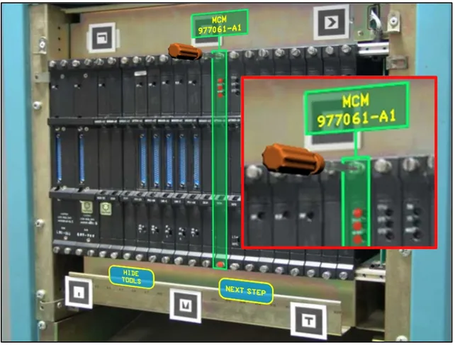
Figure 3: Panel augmented by virtual labels, tools and GUI (inset) a magnified view showing
DFA result particularly suited to model both simple and complex maintenance procedure in an easy, verifiable and legible way. The DFA representation of a particular procedure is converted in a XML file where a <step> tag defines a state. Any possible path through the automaton defines a procedure’s file.By this approach a single XML procedure file defines a specific execution order in a maintenance procedure. At runtime, this file is progressively parsed, and in every moment the user can switch to the next or previous task by means of the contact-less interface. A fragment of a generic procedure step is shown below.
<step equipmentRef=”Server.xml”>
<label rgbText="default" rgbBackground="default"> Unscrew the two fixing screws
</label>
<hotspot>screw</hotspot> <tool>screwdriver</tool> </step>
This particular step refers to the device Server.xml. A label informs user that there are two screws which have to be unscrewed. By parsing Server.xml the engine locates the screws and highlights them by means of a blinking spot. Because a screwdriver is required to perform the step, the <tool> tag allows the MR engine to locate and load the proper 3D model from the virtual content repository to render it onto the corresponding screw showing how to perform the task.
2.1.3. Finger based contact-less interface
The contact-less interface developed frees the user from the usage of any tangible I/O device to communicate with the system. The user indeed, has only to wear small rubber caps of different colors over his thumb and index fingertips, eventually of both hands. The image-based tracking exploits the same video stream used for the camera tracking to achieve fingertips detection and tracking, thus yielding a reduction of computational cost compared to a solution based on a dedicated camera and a simpler hardware
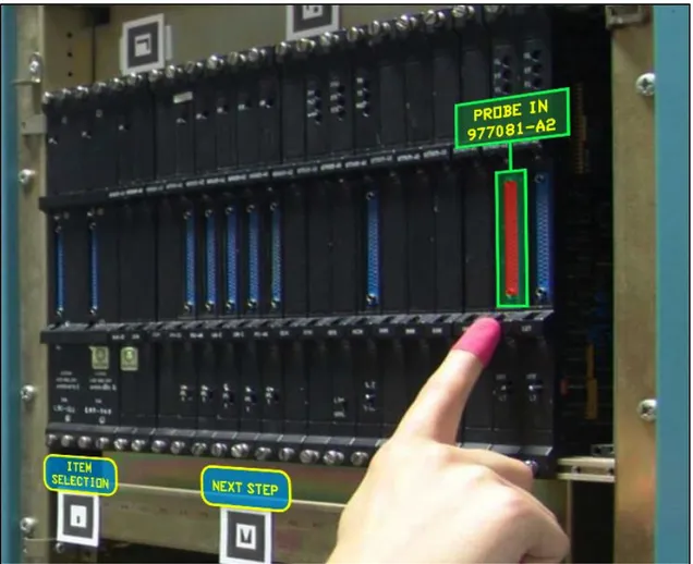
configuration. Each finger is associated to a different color according to a simple enrollment procedure repeated for each finger and generally performed only the first time the system starts-up. The fingertips samples captured are analyzed in the HSL color space to extract the dominant hue and saturation ranges, while the lightness component is used to filter out eventual highlights. At runtime, the image grabbed from the camera is subsampled (by a factor of 4 to 8 times) to both reduce the effect of camera noise and to optimize system’s performance. For each pixel in the subsampled image whose HLS levels fall within the ranges defined during enrollment, a recursive search for similar (color wise) neighbors is performed until a region of 20x20 pixels is explored. If at least one half of the pixels inside this region matches with the original pixel, then the engine recognizes that region as one of the colored caps to track (see Figure 4). This approach resulted both reliable and responsive, granting a sustained frame rate always well above 30 frame per second for an image resolution of 640x480 pixels (typical for most HMD cameras). Finger tracking enables a rich interaction paradigm that can be exploited in many different ways. For instance the user may query the working environment to learn more about it by simply moving the index finger over any hotspot (i.e., a screw, a button, a handle, a led indicator and so on) according to his point of view to obtain visual info about a particular component. Moreover, finger tracking enables operating the system by using a graphical user interface (see Figure 5). The main challenge with an intangible GUI is related to the interaction paradigm, which has to manage the lack of physical contact with the interface elements (buttons, slider, toggles etc.). Indeed, when using a conventional (tangible) interface, the kinesthetic feedback provides an important confirm of the operations performed. To address this issue, a time based interaction paradigm was exploited, requiring the user to hold the finger in position for a defined (around one second) amount of time to trigger the associated function. A visual feedback, in the form of a small progress bar drawn over the GUI element selected, inform about the selection state (i.e. hold the finger until the progress is over). The same paradigm is used during a servicing procedure to move from a step to the next one or previous one as well as to play/pause/rewind an animated virtual tool showing how to perform a specific task.
A) B)
C) D)
Figure 4 – Fingertips tracking in four steps: (A) original frame grabbed from the camera; (B)
Additionally, as the system is designed to track up to four colored caps, multi-finger gestures can be used to provide more powerful interaction modalities, like object picking, zoom or rotation.
2.1.4. Experiments and comments to the results
Two kinds of experiments have been conducted on the system described above, to assess both the performance of the tracking approach and the overall usability of the MR environment applied to a training facility. The hardware used for the experiments includes a notebook, featuring Intel I5 processor and Nvidia GeForce 9 series graphics board and an ARVision-3D video see-through HMD from Trivisio, equipped with two 800x600 LCD display and two 640x480 cameras capturing the surrounding environment at 30 FPS (see Figure 6.).
Figure 5: User interacting with the servicing assistance environment through a contactless
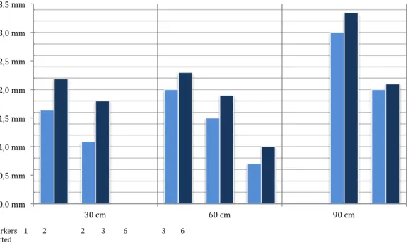
Only the left camera has been used for scene capture. During operations the notebook was contained inside a small backpack. Both the accuracy and the robustness to camera motion of the multi-marker tracking have been tested. The measurements take into account the global error amount due to the combined effect of position and rotation errors. The results are summarized in Figure 7, and they overall confirm that accuracy delivered is more than adequate for the target application. the At a distance of 30 cm an augmented point results offset respect the real position only for 1.64mm if only one marker is recognized. This error amount falls under 1.09 mm when two markers are detected. Due to rotation error if the same point is seen under an angle of 45° the error increases to 2.19 mm for a single marker. The same evaluations have been done at distance of 60cm and 90cm. Not surprisingly, as the distance increases, the number of markers recognized increases too. This ensures that the error remains small even at greater distance. In fact at 90 cm with six markers recognized the error is of just 2 mm meaning that for the user the perceived error is nearly negligible. Another important aspect affecting the tracking accuracy is represented by the camera angular velocity.
Figure 7: Co-registration error measured according to number of markers detected,
user-markers distance and off-plane angle
When the user rotates his head rapidly (this happens mostly with respect to the vertical axis), the video stream may results in blurred frames negatively affecting markers detection and recognition due to insufficient image contrast. This issue is directly related to the camera’s capturing speed, so the higher the frame rate the lower the blur produced and consequently the higher the angular velocity allowed. In the case considered, (the HMD’s camera operating at a common 30 FPS) the system was able to track the user reliably until the angular velocity is below 2 rad/sec. Over this limit a tracking failure is very likely, however as soon as the speed slow down the system recover form the error condition almost instantaneously. In any system evaluation, user testing is of great relevance in confirming the validity and the effectiveness of solutions adopted. To this aim, a user questionnaire has been prepared to assessing the perceived quality of the interaction after performing a number of tasks significant to the operating context considered. The evaluation sessions involved ten users, selected among
0,0 mm 0,5 mm 1,0 mm 1,5 mm 2,0 mm 2,5 mm 3,0 mm 3,5 mm 30 cm 60 cm 90 cm 0° yaw 45° yaw # markers 1 2 2 3 6 3 6 detected
specialized technicians with no previous experience of either MR systems or contactless interfaces. The following is a list of the tasks performed by the testers:
§ Load a new servicing procedure. § Select a particular hotspot. § Select a function from the GUI. § Toggle between two functions. § Perform a servicing procedure.
In the final questionnaire, the questions were presented using a five-point Likert scale, where respondents specify their level of agreement to a statement. In order to avoid any bias, some statements were in positive form and others in negative one. This was taken into account in the final assessment of results. The following is the list of the proposed statements:
1. Available finger based functions are easy to perform 2. Functions are too many to remember them
3. Interacting by fingers is not intuitive 4. It is easy to select objects
5. Visual aids are clear and useful
6. It is easy to operate the contact-less GUI
7. The type and number of available functions to interact with objects is not sufficient
8. Devices worn are not comfortable during operations
The answers to the questionnaire are summarized in Figure 9 above. Most participants reported a good confidence feeling during system’s usage, and some of them also reported an operational advantage in performing the proposed tasks with respect to their usual operating modality. All the participants to the evaluation sessions have also been interviewed to better understand the motivations behind the answers provided.
QUESTION I strongly agree I agree I do not know I disagree I strongly disagree 1 1 6 1 2 0 2 0 2 1 7 0 3 0 1 2 5 2 4 2 6 0 2 0 5 2 7 0 1 0 6 0 6 2 1 1 7 0 1 2 6 1 8 2 4 1 3 0
Table 1: Scores reported after subjective system evaluation according to five-point Likert scale
Most comments showed a general satisfaction about the finger-based interface, though most of them remarked the lack of a physical contact as something strange which is not easy get used to. Both the two visualization modalities were considered useful for improving the confidence and avoiding distraction errors during the operations, while, not surprisingly, the HMD caused a somewhat stressful experience to most users.
The subjective system evaluation highlights the potential of the proposed approach, though issues related to the hardware used might sometimes detract from the MR experience. According to questionnaire answers, the combination of augmentation and finger-based interface worked well, providing an intuitive interaction paradigm that proved to be suited to the application context. Overall, the MR aided servicing environment produced a valuable improvement in user’s confidence during simulated interventions, which could eventually lead to a measurable reduction of time required to tasks completion.
2.2. Diminished Reality, an Alternative Visual Strategy for MR/AR
In previous Section 2.1., it has been remarked the importance of an effective visualization strategy to maximize the potential of virtual contents augmenting the visual field for different applicative scenarios. How and when to augment real objects and environment may have a great impact on the quality of user assistance provided. For instance, in some situations the scene observed should be possibly simplified rather than augmented. To this regard the concept of diminished reality might prove useful to simplify complex assemblies and to improve user confidence during operations. Generally, this term refers to removing real-world objects from a live video stream, as demonstrated in [19] and [20]. The common idea behind these works is to remove the unwanted real object and to reconstruct the portion of the scene occluded by it exploiting multi-angle capturing, a technique not always viable in a typical AR setup. Herling and Broll [21] also propose a diminished reality environment, asking the user to select the object to hide. However, this selection could be problematic in case of a high density of components like switches, screws, etc. (not infrequent in industrial environments). There are situations, indeed, in which adding extra information to the scene may lead to an even more confusing effect. In particular, this issue might arise in environments characterized by the presence of a large amount of interaction points (e.g., a control board, a rear panel of a complex device etc). In this case, showing further information in addition to those already present might be counterproductive. These are the main considerations behind this proposal of an alternative augmentation strategy, inspired by the concept of diminished reality and based on the selective occlusion of unwanted elements rather than on image based object removal. Two different examples of this kind of “diminished reality” are reported in the following sections 2.2.1. and 2.2.2., and they are both based on the Mixed Reality Engine described in Section 2.1.2. and applied to two different contexts: the industrial environment already presented and a home-environment, targeted to the broadest possible audience and not requiring dedicated hardware.
2.2.1. Selective removal of equipment features
As recalled before the MRE is able to support two different approaches to scene augmentation. Indeed, beside the “classic” strategy consisting in the visualization of different kind of virtual objects (e.g., arrows, labels, 3D models and so on) onto the captured scene, it can even remove distracting items from the field of view, leaving as visible only the elements required to perform the desired task. The goal in hiding part of the operating environment is to let the user focus on the physical elements on which to perform a particular task. From a more technical point of view, to the purpose of hiding real objects or part of them the engine renders an occluding (polygonal) surface on which can be applied either a diffuse map or an opacity map. By exploiting the device’s formal representation (see section 2.1.3.), the engine either load the associated textured polygons (see Figure 8_bottom) or it builds up a procedural texture consisting of a black background featuring white “holes” of various shapes (e.g, circles, squares, polygons and so on) corresponding to the hotspots that should stay visible. All the necessary information to perform this task is available in the working environment database. Once the textured polygons are built, the engine renders it over the real device (see Figure 8 _top) occluding all the contextually not relevant hotspots. Both the more common augmenting and the diminishing strategies are meant to improve user’s operational capabilities, however, there are contexts in which one is more suited than the other. Which of the two visualization methods should be used depends on the total number of hotspots present in the surrounding of the virtual contents visualized at a given step of the intervention. If the density of the hotspots exceeds a threshold then the diminishing modality is preferred. Anyhow, the user may always switch to the other modality in any moment by means of a specific Augmented/Diminished View toggle present in the visual interface. Finally, by combining both augmented and diminished reality a third hybrid visualization approach could be realized, providing a simplified view of the operating field in which only the elements left visible are augmented with additional info. Whatever the strategy adopted, scene augmentation or diminution is made possible thanks to a formal scene representation based on XML. The XML database consists of a collection of files providing the necessary information to correctly locate each relevant element of the working environment within the 3D space.
Figure 8: Original frame (top) and diminished view (bottom). Only the required elements are
2.2.2. A WYSIWYN approach to objects augmentation
In the last years, the growing diffusion of lightweight portable computing device like netbooks, tablets, and smartphones, featuring adequate processing power coupled with trackpad/touchpad interface, one or two webcams and eventually additional sensors (accelerometers, gps, gyroscopes, digital compass, etc.) has provided a low-cost platform to augmented reality applications, usually relying on more dedicated but also expensive and bulky technologies like see-through head mounted displays. There are several contributions, in literature, based on this technological premise. Counter Intelligence [22] is a proposal for a conventional kitchen augmented with the projection of information onto its objects and surfaces to orient users, coordinate between multiple tasks and increase confidence in the system. CyberCode [23] is a visual tagging system based on a 2D-barcode technology and provides several features not provided by other tagging systems. CyberCode tags can be recognized by the low-cost CMOS or CCD cameras found in more and more mobile devices, and it can also be used to determine the 3D position of the tagged object as well as its ID number. Chuantao et al. [24] present a contextual mobile learning system framework, enabling to learn mastering domestic and professional equipments using mobile devices like Tablet PC, PDA or Smartphone and exploiting RFID technology to achieve contextualization. Gausemeier et al. [25] describe an image based object recognition and tracking method for mobile AR-devices and the correlative process to generate the required data. The object recognition and tracking base on the 3D-geometries of the related objects.
The purpose of this application is to showcase how the AR architecture described in 2.1.3. can be successfully re-engineered for applications targeted to everyday objects and environments and requiring inexpensive hardware like a compact netbook or a tablet PC. In particular, the proposed system is focused on providing accurate augmentation of AV components by means of visual aids to ease the most complex procedure involved with the advanced use of this diffused hi-tech equipment, which hardly could be performed without referring to the user manual. The system supports either the typical “additive” augmentation paradigm (co-registered graphics like labels or 3D objects) or the so called “mediated” or “diminishing” approach to AR, consisting in the “What You See Is What You Need” (WYSIWYN) approach to selective removal
of part of the physical object to focusing user attention only on the visual features required in a particular operative context. One interesting aspect of this system is that a portion of the user/machine interface is the same augmented device. Its buttons, labels, handles and so on are the graphical interface widgets of which the user disposes to interact with the system. During any operation, the user can choose if sending the suggested commands by trackpad/touchscreen interface or directly on the device. In the former case the AR engine sends the command to the device through a serial communication interface acting as a middleware. In the latter case the system acts only as a virtual assistant.
Figure 9. The main system components.
AR Engine On board Camera Calibration GUI ARToolkit Marker recognition Augumented objects repository Tracking coord. video stream User Video stream Augmented contents Final rendering + Device RS232 Trackpad/Touchpad interface sends a command Rendering to LCD display sees
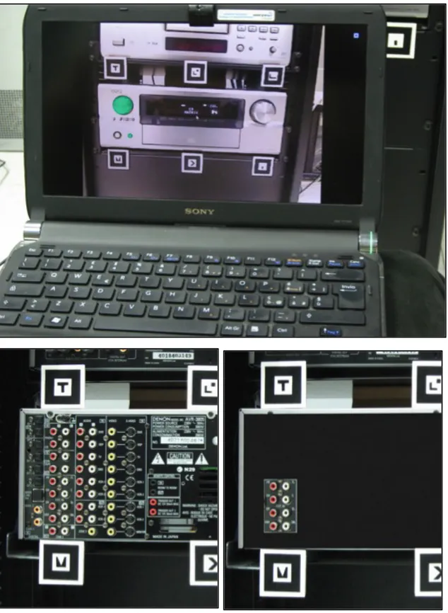
Figure 10. Six markers surrounding an AV component. Each marker is a 4 cm. side square.
The overall schematic view of the system is shown below in Figure 9. The AR engine is the main system component. It is built on Quest3D, a commercial authoring environment for real-time 3D applications featuring an “edit-while-executing” programming paradigm [26]. Each scene augmentation is applied to specific hotspots defined over the AV component by means of previous measurements and a XML database is used to record the precise hotspots locations. When the user points the camera toward the component, the AR engine load the corresponding XML file. The syntax of a device file consists essentially of a list of <hotspot> tags. An <id> tag allows the engine to recognize any hotspot from each other while a <shape> tag is exploited as approximation of the hotspot real shape to highlight it when required. A <details> tag provide short information about the function of the hotspot. Any hotspot tag has three child tags <position>, <rotation> and <size> which represent the relative hotspot’s 3D transformation with respect to the multi-marker’s reference system. The
AR engine, according to the aforementioned descriptors, builds up the virtual scene by means of a DOM XML parser. To find the required data in the application database a XML-based XPath query language is used. Combining the information from tracker and from XML database, the AR engine is therefore able to locate in every moment the user in the real world and to extract all the required augmenting contents from the repository. This repository consists of either 2D or 3D objects (eventually animated) such as text labels, graphics and parametric “occluding objects” used to selectively hide features of the real component. An example of a typical tag structure for a hotspot is listed below: <hotspot>
<id>OnOffButt</id>
<label>On/off button</label> <shape>circle</shape>
<details>This is a on/off button</details> <position x="0.0" y="0.0" z="0"></position> <rotation x="0" y="0" z="0"></rotation> <size x="0.01" y="0.01" z="0.01"></size> </hotspot>
For any augmented hotspot the engine allows the user to edit his/her preferred attributes. When the user selects an interested hotspot he/her can associate to the selection the required visual aid. These attributes are stored in an external XML file associated to the AV component. The engine also provides an editor which allows the user to edit his/her manual information. The editor generates for each component an XML compliant file which can be used for augmentation. This feature can be handy if the user wants a custom documentation written according to his/her needs. Besides the augmentation, the engine performs another crucial task that is the support to complex procedure like, for instance, 7.1 surround installation and setup. Each procedure can be represented as a finite deterministic automaton (DFA). According to this approach, a particular state represents a procedure step and its links define the execution order. DFA result very suited to this context providing all the elements (states, links) required to
represent both simple and complex procedure in a easy, verifiable and legible way. It results convenient to convert the DFA representation of a particular procedure in a XML file, exploiting the above mentioned DOM parser and query language. The user can switch to the next or previous step using the trackpad/touchpad. At each step the system might suggests the user how to operate the device, explaining the purpose of the operation and the involved hotspot. An example of a simple step is described below. <step>
<label rgbText="default"
rgbBackground="default">Turn off the device</label> <hotspot id="OnOffButt"></hotspot>
</step>
The “subtractive” augmentation capability is able to hiding part of the AV component to let the user focus on the elements of the physical interface required to perform a particular operation, thus avoiding the confusion due to information overload. This represents a mediated or diminishing approach to augmentation, and rather than adding visual contents, all hotspots are hidden except those involved in the current operation. It is strictly based on the techniques exposed in section 2.2.1. and adapted to be performed on a less powerful mobile computing platform (a notebook or even a tablet). Advanced AV components may be equipped with a RS232 bidirectional serial communication interface. For those components, the system provides access to any functionality also by means of the netbook/tablet touchpad instead of operating directly on the device. To the aim of testing the proposed system in facilitating the usage of a commercial AV component, it in a real applicative scenario: the augmentation of a Denon AVR-3805 surround receiver during two not trivial procedures (level equalization and input-output wiring) which typically force the user to refer to a voluminous manual. Generally any receiver/amplifier is characterized on the front panel by a variable number of buttons, switches, knobs etc. controlling for example, source selection, sound effects and so on.
Figure 11 Top: an additive augmentation of front panel highlighting a knob and a button.
Bottom: subtractive visualization strategy showing the actual rear panel (left) compared to the mediated version (right) with only the connectors required.
On the other side the rear panel is much less used but is crowded by a big number of I/O connectors whose correct usage depends on the comprehension of the particular wiring scheme chosen. The test-bed used for experiments is based on a Sony Vaio netbook featuring Intel dual core processor and Nvidia Quadro FX-500 series graphics board. The scene capturing is performed by a Logithech Camera C905 providing a video resolution of 800x600 pixel at 30 fps. This hardware setup has been capable to render an augmented scene featuring up to thousands of polygons providing a sustained frame rate always above 30 fps (limited to the camera’s fps). During the AR assisted operations the user sees through the netbook’s LCD display the virtual contents rendered over the captured scene. This design allows the user to focus on the relevant items to perform the required tasks. Clicking with mouse pointer on a specific device’s hotspot, the system shows some short technical data.By double-clicking an additional window is shown, which contains the detailed information for the selected hotspot. Both additive and subtractive approaches to augmentation have been tested (see Figure 11) according to the considerations drawn above, so the additive approach has been tested on the frontal panel of the amplifier whereas the subtractive has been tested on the rear panel.
2.3. Handling Occlusions While Interacting In Mixed Reality Environments
As the number of augmented and mixed reality applications available on a variety of platforms increases, so does the level of interaction required, possibly leading to the emergence of challenging visualization issues. To this regard, it is worth to note that the illusion of the co-existence of virtual objects in the physical world (the essence of MR paradigm) is typically made possible by so called video-based1 see-through approach in
which the rendering of virtual contents is superimposed onto the surrounding environment captured in real time by means of a proper transformation. This trick works well until the order of the planes to be composited is coherent to their distance from the observer (see Fig. 12_Left). But, whenever an object of the real world is expected to occlude the virtual contents, the illusion vanishes since the order of rendered planes does not lead to a correct visualization (see Fig. 12_Right). As a result, what should be seen behind a real object could be visualized over it instead,
Figure 12. Left: A virtual model of a keyboard rendered onto a captured frame of real
environment to augment it. The hand positioned along the right side of the keyboard does not ruins the Mixed Reality illusion. Right: The same MR scene, but as the hand is positioned over the keyboard, it is occluded by the virtual content.
generating a “cognitive dissonance” due to the loss of spatial coherence along the axis normal to camera plane that may compromise scene comprehension and, ultimately, the interaction capabilities during the MR experience. Hand occlusion in augmented reality is a challenging topic and scientific literature presents diverse approaches to it.
In particular, displaying occluded objects in a manner that a user intuitively understands is not always trivial. Furmanski et al. [27] in 2002 developed new concepts for developing effective visualizations of occluded information in MR/AR applications. They designed some practical approaches and guidelines aimed at evaluating user’s perception and comprehension of the augmented scene and distances. Many researchers aimed at solving the incorrect occlusion problem by analyzing various tracking methods or by integrating vision-based methods with other sensors [28]. Lee and Park proposed to address this issue in AR environment introducing the usage of an Augmented Foam [29]. A blue foam mock-up is overlaid with a 3D virtual object, which is rendered with the same CAD model used for mock-up production. By hand occlusion correction, inferred by color-based detection of the foam, virtual products and user’s hand are seamlessly synthesized. The advantage of the augmented foam is that it is cheap and easy to cut allowing to realize simple and complex shapes. On the other hand, it imposes that for all augmented objects has to be present in the scene the physical counterpart made of foam. A color-based similar approach is discussed by Walairacht et al [30]. They exploited the chroma-key technique to extract only the image of the hands from a blue-screen background merging the image of the real hands and the virtual objects with correct occlusion. Although chroma-key is particularly fast and efficient, it requires the use of a colored background that represents a not feasible solution in many environments. In addition, it does not provide any information about real objects in the scene and their spatial distances. Buchmann et al [31] also handled hand occlusions in augmented reality exploiting marker-based methods to determine the approximate position/orientation of user’s hands and, indirectly, their contour to fix the visualization order. The disadvantages are the inconvenience to wear specific gloves featuring fiducials on each finger and the rough level of accuracy in the segmentation of the hand from the background. In the field of medicine, Fischer et al [32] exploited a Phantom tracker and anatomic volumetric models in order to support surgical interventions resolving occlusions of surgery tools. They presented a simple and fast preprocessing pipeline for medical volume datasets which extracts the visual hull volume. The resulting is used for real-time static occlusion handling in their specific AR system, which is based on off-the-shelf medical equipment. Depth/range cameras (e.g. the
Kinect by Microsoft) have also been proposed [33][34][35] to provide a real-time updated depth-image of the surrounding world that can be conveniently used to evaluate whether a pixel from the captured environment is closer to the observer than the corresponding rendered pixel of virtual content, or not.
This technique can lead to a more accurate result and also enables evaluating distances of real objects in the scene and their inter-occlusions with virtual objects. However, it requires additional hardware (usually an infrared pattern emitter and a dedicated infrared camera) and it should match the field-of-view of the see-through cameras, to works effectively. The generation of a disparity map by using stereo matching techniques [36][37] represent the most suited choice to correctly segment user’s hands in AR environments. Results produced by this technique are comparable to the ones form depth cameras without requiring dedicated hardware, which is a central aspect of this study.
The following sections describe the proposed method to addressing effectively hand occlusion in many MR/AR interaction contexts without any additional hardware, apart from video see-through goggles enabling stereo-vision. In brief, the rendered virtual objects are composited onto the incoming video see-through streams according to a disparity map encoding real-to-virtual visualization order at a pixel level as a gray-scale image by means of stereo matching. The disparity map is generated by a belief propagation global algorithm [38] that exploits GPU’s highly parallel architecture for speeding up required calculations and for enabling real-time applications. The performance of the algorithm is optimized by segmenting the input image between hand and not-hand regions via a skin-tone filtering in the HSV color space (less affected from lighting conditions than RGB space). The purpose of this segmentation is twofold. From the one hand it is possible to reduce the region of interest (that directly affects the computational cost of the disparity map) to a cropped region of the original frame, on the other hand the contour of the segmented hand region is used as a reference to improve the edge sharpness of the disparity map. Some ad-hoc improvements aimed at further reducing the computational cost of the original algorithm are discussed in the following section.
2.3.1. The approach at a glance
The proposed processing pipeline is shown in Fig. 13 The diagram highlights the main elements in the image-processing pipeline. The user wears a HMD with two embedded cameras enabling stereo vision. Two separated video streams, from left and right camera respectively, capture the real scene from a different perspective point. On each stream, a simple and fast skin detection technique detects the user’s hands in the scene. The binary image is used to apply a vertical crop to the original frame that preserves the region, including the foreground and the background, where the hands appear. On that crop two disparity maps, the one for the real scene captured and the other for the rendered content, are generated by exploiting a stereo-matching with belief propagation technique. The disparity maps are used to estimate the position of the hands in the field of view with regards to the virtual scene.
Fig. 13. The overall architecture of the approach proposed.
Final compositing Scene Capturing
Skin Detection & Region Cropping
Disparity maps generation
(hands and virtual objects)
Image merging and smoothing
Video streams from webcams
Augmented streams to HMD displays with hand occlusions
The occlusion correction is achieved by comparing them and combining the result with a skin-based segmentation of the hand. An edge blurring pass is applied to the segmentation in order to smooth the edges of the hand region. The combination of disparity map with blurred color-based segmentation of hands produces a cleaner approximation of the occlusions that can be applied as top-level layer of the augmented streams sent to the HMD displays.
2.3.2. Method description
The first step consists in capturing the scene observed by the user through the webcams mounted on the HMD. Since the HMD is intended for a stereoscopic vision, the streams from left and right camera capture the scene from a slight different point of view. Each of the two streams is therefore separately augmented by rendered virtual contents throughout the pipeline. Even though this implies a greater computational cost of the augmenting algorithm, it preserves the binocular vision of human eyes leading to a more reliable augmentation of the scene and the occlusion correction. Fig. shows one frame captured by one of the cameras mounted on the HMD while the user wears it.
To keep computational cost of the following steps slow, the frame is properly cropped so that the algorithm can focus the execution only on the relevant portion of the entire frame. The cropping is performed by a simple and fast skin color-based technique. It converts the video frame from the RGB to the HSV color space in order to have a simply way of filtering the color of naked hands by proper ranges of hue and saturation, thus leading to a gray-scale mask. Fast closure operators enable removing little irrelevant blobs in this mask and filling holes (if any) in main closed regions (the hands in our context). Every pixel inside the region boundaries (the hands’ contour) is therefore set to full white (see Fig 15a). The intersection of this first mask with the rendered content’s alpha channel (see Fig 15b) results in a new mask which limits the region on which the disparity maps of rendered content has to be computed (see Fig 15c). To this aim, stereo matching with belief propagation is therefore performed on these cropped regions. By processing only a limited region of the whole scene, it has been possible reducing the computational costs of this step, which is the most time consuming in the processing pipeline. Firstly the matching costs for each pixel at each disparity level in a certain range (disparity range) are calculated. The matching costs determine the probability of a correct match. Afterwards, the matching costs for all disparity levels can be aggregated within a cross-shape neighborhood window. Basically the loopy belief propagation algorithm first gathers information from a pixel’s neighbors and incorporate the information to update the smoothness term between the current pixel and its neighboring pixels, and to iteratively optimize the smoothness term thus resulting in global energy minimization.
Each node is assigned to a disparity level and holds its matching costs. The belief (probability) that this disparity is the optimum arises from the matching costs and the belief values from the neighboring pixels. For each iteration, each node sends its belief value to all four connected nodes. The belief value is the sum of the matching costs and the received belief values. The new belief value is the sum of the actual and the received value and is saved for each direction separately. This is done for each disparity level. Finally, the best match is the one with the lowest belief values defined by a sum over all four directions resulting in the final hand(s) disparity map.
The main factor that affects every stereo-matching technique is the number of disparity ranges considered during the matching cost function. The more values are considered the more the disparity map is reliable but, the more the cost increases. Considering the main goal of performing a fast hands occlusion correction, the number of disparity ranges has been reduced. The rough disparity maps (obtained by composing it with the corresponding crop of the binary image from skin detection acting as alpha layer) has been refined by means of one pass of edge blur allows to smooth the edges of the color-based segmentation. The result is a smoother segmentation of user’s hands (see Fig. 5d) that can be used for final compositing (Fig. 15e). For what concerns the rendered content, it would be simpler and faster to exploit the accurate depth info contained in the Z-buffer, but matching it coherently to the depth levels encoded in the hand(s) disparity map would be a not trivial task.
Fig. 15. Skin detection with closure functions refinement (a). Alpha channel of augmented
objects rendered onto the video stream (b). Disparity map of user’s hand segmented from the scene by the skin color-based detection (d). Disparity map of the crop of the region where augmented virtual contents overlap the hand (e).
(a) (b) (c)
Fig. 16. Compositing and final result. The original real background shown in Fig. is
composited according to the disparity map of the scene enabling a correct visualization and a meaningful interaction (note that hand’s casted shadow is not currently handled by the proposed method).
The final composited frame is obtained by comparing pixel-wise the gray level of the two disparity maps. The pixel whose gray level is lower than its homologous is considered not-visible from the observer’s point of view and is discarded. Fig shows an example of the final result in which the hand of a user interacting in a MR environment is properly composited onto the augmented content.
2.3.3. Experimental results
Preliminary experimental trial of the proposed technique in a MR environment has been performed on a test-bed featuring an i7 Intel quad_core processor and an Nvidia GTX760 graphic board equipped with 1152 cores and 2 GB of VRAM. The user worn a Trivisio HMD that features stereo capturing by two embedded webcams (752x480 resolution, 6oFPS) and stereo vision by two 800x600 LCD displays (see Fig. 17).
Even though the method described in this thesis3.5 exploits time consuming algorithms, it meets the requirements of real-time application because it works only on a fraction of the whole captured scene. In addition, the improvement provided by utilizing graphics hardware acceleration makes possible to combine the time demands of stereo matching with typical marker-based tracking of the user on a stereo video stream. Table 2. summarizes the performance measured during the experimental session. In particular, the table shows the frame per second achieved by the proposed solution when the disparity maps are generated for 16 and 32 ranges of disparity values. During the experimental trial the user is free to move his/her hands thus implying a size of the crop of the scene that varies over time. During normal condition of interaction, the number of pixels of user’s hand covers about 1/8 to 1/6 of the whole scene for over 60% of the experimental session. When the distance between user’s hand and the point of view results shorter, e.g., the user brings his/her hands closer to the cameras, the stereo matching works on a wide crop of the scene leading to a drop in performances to the limit of a smooth real-time rendering. Future improvement of this method could take into account such issue providing an adaptive amount of disparity levels to consider during the matching cost function.