Electromagnetic Models for Passive Tag-to-Tag
Communications
Gaetano Marrocco, Member, IEEE, and Stefano Caizzone
Abstract—The UHF passive radio frequency identification
tech-nology generally enables an asymmetric interaction between the reader and the tag, the latter only being able to respond to the query of the reader through backscattering modulation. Very re-cently, some experiments put into evidence the possibility to set up a tag-to-tag communication by using a simple illuminator. The key issues and the physical limitation of such a cross-link are here in-vestigated both theoretically and numerically by fully accounting for the mutual coupling among the tags, their radiation proper-ties and the impedance modulation. The analysis reveals that the cross-link range may be optimized by a proper design of the tags’ input impedance and that alignment of a multiplicity of tags could be able to communicate according to a simple routing strategy.
Index Terms—Array, mutual coupling, RFID, sensors, wireless
communications.
I. INTRODUCTION
R
ADIO frequency identification (RFID) is a fast growing technology with countless applications in the control of items, the security assessment, the pervasive monitoring of en-vironmental parameters and the biomedical sensing [1]. Within the current communication modality, tags are interrogated by a standalone reader or by a radio unit embedded into more com-plex devices such as a smartphone. The tags are usually passive and the communication is only possible between the reader and the tag that replies to the reader itself by means of reflection, on changing its radar cross-section. Tags are therefore not directly aware of the presence of other tags. The inter-tag communica-tion is possible only in case of active devices acting as wireless sensor nodes.The concept of tag to tag (T2T) communication between passive UHF RFID tags has been introduced very recently in [2] by Nikitin, Rao and Lam. Two tags placed in close proximity may in principle directly communicate even in the absence of an RFID reader. What is required is just an illuminator radiating a continuous wave able to power up the tags. They could hence communicate through backscattering modulation of such a CW carrier. Actually, passive UHF RFID protocols do not support this kind of interaction since the microchips usually
Manuscript received November 30, 2011; revised April 29, 2012; accepted June 25, 2012. Date of publication July 11, 2012; date of current version October 26, 2012. This work was supported by PRIN-2008 MULTITAG.
G. Marrocco is with Pervasive Electromagnetics, University of Rome, Tor Vergata, 00133 Roma, Italy (e-mail: [email protected]).
S. Caizzone is with the Institute of Communications and Navigation, German Aerospace Research Center (DLR), Oberpfaffenhofen, Germany and also with the DISP, University of Rome, Tor Vergata, 00133 Roma, Italy (e-mail: stefano. [email protected]).
Digital Object Identifier 10.1109/TAP.2012.2208087
receive an ASK-modulated signal from the reader while they backscatter according to an FSK modulation. Nevertheless, this envisaged new technology could open new frontiers in distributed processing such as ubiquitous interaction for person to person, person to object and object to object paradigms as well as collaborative pervasive sensing.
A preliminary experimental proof of T2T communication has been given in [3] by means of an emulator of a chip able to receive signaling from a passive tag. The physical potentiality and limitations of T2T communication are however still to be discovered, and versatile modeling tools are required to under-stand and master the design of interacting-oriented tags. The T2T communication is based on a near-field interaction so that the usual Friis and Radar formulas can not be used to charac-terize the link, since a key role is played by the mutual coupling. In this view, this contribution presents a theoretical investiga-tion aimed to characterize the inter-tags channel and to derive the performance parameters useful to set up some design guide-lines. In particular it is of interest to define the modulation depth and its relationship with the inter-tag distance, geometry, and impedance matching. The modulation depth can be assumed as a merit factor of the T2T channel since it should be high enough (more than 50%) to enable the microchip comparator to discrim-inate the binary states.
A full understanding of the phenomena is carried out by the help of the mathematical formalism of the RFID Grids recently introduced by the authors in [4] and demonstrated in [5] which is here carried on to a step forward with the aim to account for the modulation-level interactions among the tags. The theoret-ical results are finally discussed by means of some simulated examples concerning couplets and larger alignments of tags.
II. THERFID CROSS-LINK
With reference to Fig. 1, a T2T communication requires at least an external electromagnetic power source, denoted as il-luminator, which could be much simpler than an UHF RFID reader since it needs only to include a CW transmitting module. This kind of object has been already considered in bistatic RFID links, as well as in recently proposed link-extender systems [6]. The illuminator is here electromagnetically characterized by its effective length and by the radiated . For the sake of simplicity, just two tags are here visualized, but the proposed formulation may describe any number of elements. It is assumed that the th tag, denoted as talker, is performing backscattering modulation at the considered time-instant, and hence it acts as the transmitter, while the th tag is the listener. It is worth noticing that the receiving tag is collecting power from both the illuminator and the talker tag. So we denote as direct link (or power link) the power exchange from the illuminator to the 0018-926X/$31.00 © 2012 IEEE
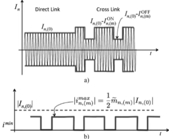
Fig. 1. Scheme of tag to tag communication wherein the required power for the cross link is provided by an external illuminator.
tag, and with cross-link(or data link) the data exchange between the two tags. The radiating properties of the tags are summa-rized through the embedded effective lengths and gains and , respectively.
The close interaction between tags is such that they have to be regarded as a unique electromagnetic loaded receiver/ scatterer provided with multiple ports. This object can be fully described as a distributed multi-port network, an RFID Grid [4], characterized by the impedance matrix and by the
di-agonal impedance matrix of
loading RFID microchips, where the superscript indicates the impedance modulation enforced by the microchips.
Denoting with the Grid
admittance, and with the vector of open-circuit voltages collected at the tags’ port, where
(1) (2) and , the total currents over the microchips
of the grid are . The induced current
over the th tag is hence given by
(3) where indicates the th row of the grid admittance ma-trix. When the th tag is performing impedance modulation be-tween an OFF and an ON state, the admittance matrix may be decomposed into an unmodulated part , with the diagonal matrix of the input impedances of the microchips in the scavenging mode, and a perturbed part in-cluding the specific modulation features (see [4] for all the de-tails)
(4)
Fig. 2. Contributes to induced current at th microchip: a) example of unmod-ulated current (direct link) and modunmod-ulated current (cross link). b) example of demodulated signals after carrier suppression.
where the modulation-dependent parameter is
(5) The current over the receiving nth tag when the th is modu-lating its impedance may be hence rewritten as linear superpo-sition of two contributes
(6) The first addendum
(7) is the induced current over the th port due to the direct link (i.e. without modulation), which accounts for the mutual orientation between the tags and the illuminator through the normalized gain vector , while the second contribute
(8) accounts for the cross-link, e.g., for the modulated field due to the impedance switch at the th tag (Fig. 2).
III. MODULATIONDEPTH ANDPOWERS
It is now introduced the modulation depth for the cross link between the th listener tag and the th talker tag which de-scribes the electrical distance between the two ON/OFF states: (9) (10) The smaller is , the more tricky will be the discrimi-nation of the data-bit for the listener. Assuming modulation data encoded by the tag according to the FM0 or Miller scheme and
perfect matched filter demodulation, the minimum and max-imum currents ([7]–[9]) at the microchip detector are
and , respectively and hence from (9):
(11) It is worth noticing that the modulation depth is definitely de-pendent on the tag-to-tag distance through the coupling matrix . This is a different behavior with respect to a standalone tag performing backscattering modulation toward the reader, and it is due to the close interaction between direct- and cross-links.
A. Modulation Efficiency
The average power carried by the modulated backscattered signal, and collected by the receiving chip, right after carrier suppression is:
(12)
The quantity is the available
power at the th chip in absence of backscattering modulation
of the th chip, i.e. is the power directly scavenged by the th tag only due to the CW wave emitted by the illuminator. It is hence possible to define the modulation efficiency as that portion of the available power at the th listener tag which is associated to data:
(13)
B. Case of ASK Modulation
Modulation depth and efficiency depend on the mutual ori-entation between the tags and the illuminator (described by the operator ) as well as on the specific choice of the modulating impedances , and not least on the inter-port cou-pling through matrix embedding the tag-to-tag distance and alignment. For the particular case of ASK modulation with con-jugate match in one of the two states and total reflection in the
other, and , the modulation depth
reduces to
(14)
In general, since if , it follows that
the cross-link interaction is not reciprocal ( ), apart for symmetric arrangements of tags, as discussed in the next section. This means that on interchanging the roles of talker and listener, the modulation depth of the transmitted signals through the cross-link may be different.
As demonstrated in [4], the scavenging properties of a tag subjected to electromagnetic interactions with other tags are represented by the embedded realized gain which is measurable by a con-ventional RFID reader [5] and plays the same role of the
corresponding parameter of isolated tags. Thus, by assuming talker and listener antennas as connected to microchips of a same family, (14) is rewritten in a more comfortable form:
(15) The modulation depth is hence dependent on the admittance parameters but also on the ratio between the realized gains of talker and listener toward the position of the illuminator and in principle could be more than the unitary value. A couple of interesting particular cases are described later on in Section IV concerning the analysis of the two-tags interaction.
C. Power Considerations
It is worth analyzing if the listener th tag may have enough power to be activated during the impedance modulation of the th tag, e.g., if the average scavenged power exceeds its sen-sitivity threshold. By the sake of simplicity, the ASK modula-tion is again considered for the following discussions. In this case it is easy shown that the powers at the two microchips, (see Appendix) averaged over ON and OFF impedance states (as-suming equal probability of occurrence), are:
(16) (17) with
(18)
so that . Both talker ( th) and listener
( th) tags will collect enough power to turn on and keep on performing backscatter modulation provided that the following
conditions hold at a same time: , and ,
where are the microchips’ thresholds, and hence (19) (20) Under the simplifying, but not limitative hypothesis, of iden-tical tags, symmetrically oriented with respect to the illuminator, e.g., , it is possible to verify that the first inequality includes the second one, since
is always true. This means, therefore, that the listener tag has al-ways enough scavenged power to be turned on when the talker tag is performing backscattering modulation. The ability to de-code the information is however conditioned to the modulation depth as discussed before and further specified for a two-tags case in the next Section.
D. Bit Error Rate
The quality of T2T channel can be characterized by the Bit Error Rate (BER). As in [7], by assuming that the signal
col-lected onto the listener tag is corrupted by AWGN with standard deviation , the at the th listener when receiving from the th talker tag can be expressed in terms of the com-plementary error function
(21) Thus, may be in principle minimized for a high value of induced current from the direct link, e.g., when tags are placed close to the illuminator, but even when the modula-tion depth . As it will be discussed in the next Session, the maximization of the modulation depth requires a proper impedance matching strategy accounting for the electromag-netic coupling among tags.
IV. A TWO-TAGSSYSTEM
Equation (14) is of general application and it is able to predict the modulation depth for any kind and number of tags, their mutual orientation and position with respect to the illuminator. For two tags of a same family, the impedance matrix is fixed by the self and mutual impedances and and the grid admittance matrix is hence
(22) The modulation depth may be accordingly written as
(23)
Denoting with a normalized mutual
impedance, above equation is rewritten in terms of open-circuit gain of the two tags and of polarization mismatch:
(24)
So, the modulation depth strongly depends not only on the mutual orientations and distance among tags, through the impedance factor , but also on their mutual orientation with respect to the illuminator through gain and polarization mismatch. Two particular alignments are discussed next.
A. Listener Isolated From the Illuminator
If the listener tag (the th one) is in polarization quadrature (Fig. 3(a)) with respect to the illuminator, e.g., , such a tag is not directly able to scavenge power from the illuminator but is indirectly sourced by the backscattered field emitted by the close tag. In this condition the modulation depth (24) be-comes
(25)
Fig. 3. a) listener isolated from the illuminator . b) talker and listener in symmetric position and polarization with respect to the illuminator
.
regardless of the distance among the interacting tags. However, the successful establishment of the link is still conditioned by the amount of power scavenged by the talker.
B. Symmetric Talker-Listener Arrangement
For a symmetric arrangement (Fig. 3(b)) of the two tags with respect to the illuminator (i.e. and along the direction of the illuminator), the modulation depth accordingly simplifies in the very compact form
(26) and the T2T interaction becomes reciprocal.
V. MODULATIONDEPTH VS. THEIMPEDANCEMATCHING The impedance matching between each tag and its microchip significantly affects the modulation depth through the elements of the grid admittance matrix, as formally visible in (14) and (26). Standalone tags are usually designed to achieve conju-gate impedance matching to the chip, e.g., , for maximum power scavenging. In [4] it was instead demonstrated that the optimum matching strategy for strongly coupled tags is the Hermite condition , where is now the ac-tive impedance of the th tag measured inside the grid when all the tags are performing power scavenging. It will be shown in the following subsections that the two choices of antenna impedance will provide different modulation depths and accord-ingly different T2T ranges. All the presented analysis are re-ferred to a symmetric alignment of the two tags, as introduced in Section IV-A.
A. Impedance Matching for Standalone Tags
A couplet of half-wavelength dipole-like tags is now con-sidered. The self admittance is approximated by the input impedance of the dipole in standalone condition (no cou-pling), . It is hence assumed that the microchip impedance is matched to the antenna standalone impedance,
e.g., , and therefore .
Within above hypothesis, the modulation depth in (26) reduces to
(27) The tags are mutually parallel so that the formulas in [10, p. 417] may be applied to estimate the mutual impedance . By
Fig. 4. Theoretical modulation depth of a two faced dipole-like tags versus the inter-antenna distance.
some mathematical manipulations (see Appendix) the modula-tion depth can be rewritten, for , as follow
(28) where is the Exponential function ([11])
(29)
and , , .
It is possible to see from Fig. 4 that the maximum modulation depth is for infinitely close dipoles, while this
value linearly falls down to for .
This is the same modulation depth of the backscattered signal radiated in the free space by a standalone tag as described in [8], [9].
Above theoretical estimation is corroborated by the experi-ments in [3] wherein the maximum inter tag distance was found to be around 25 mm, in agreement with what predicted by our simulations, e.g., a modulation depth 50% for inter-tag dis-tance (roughly 30 mm @900 MHz).
B. Hermite Impedance Matching
The maximum power transfer between the RFID grid and each microchip requires [4] the impedance relationship
. Since the elements of the impedance matrix depend on the mutual distance among the tags, the above con-dition must be referred to a reference distance . It is worth re-calling the power transfer coefficient for a two-ports symmetric
system which, in case of
Her-mite matching reduces to
(30) and may be higher that 1 in case of mutual impedances having negative real part. Under such a condition, the modulation depth becomes:
(31) which is hence less than 1 in case of real antennas . Such an expression can be cast in a more general form through
Fig. 5. Isolines of modulation depth versus the normalized self-impedance and of the two-tags system in case of Hermite impedance matching for three different impedance phase angle of the RFID microchip. The white circle indicates a possible realization with , corresponding to .
a proper normalization of by the impedance of the chip. It is hence introduced the impedance phase angle
of the RFID microchip as in [12], and the normalized self
re-sistance and reactance and . The
modulation depth is hence rewritten in a parametric form (32) The isolines for are ellipses (see Fig. 5) whose eccentricity is controlled by the parameter . The values of self impedance such to maximize the modulation depth is therefore required to lay over ellipses of smaller and smaller size as the impedance phase factor increases. Values of with true physical meaning are those for which is reasonably a few times larger than the true microchip’s resistance. For large microchips, (see Fig. 5 bottom), the system becomes very narrow-band and small changes in , especially in the reactance, may produce abrupt degradation of the modulation depth.
For example, assuming a microchip with impedance typical of commercial devices, a fea-sible goal in the antenna design is to achieve a layout with self
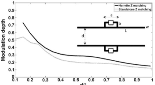
Fig. 6. Two T-match tags with different kind of impedance matching: mod-ulation depth vs. antenna separation. Wavelength corresponding to frequency . Size (in [mm]): ; Conjugated matching: ,
, . Hermite matching , , .
in Fig. 5) to which corresponds, after Hermite matching
con-dition, the mutual impedance . The
re-sulting modulation depth and power transfer coefficients will
be and , respectively.
VI. NUMERICALEXAMPLES
Some numerical examples are here reported to better dis-cuss the feasibility of tag-to-tag communication in some re-markable RFID grid layouts. In all the considered cases the systems have been modeled by the Finite-Difference Time-Do-main solver which provides, for the specific arrangement, the impedance matrix as well as the open-circuit gains, which are hence used, through (14), to calculate the modulation depth by post-processing.
A. Two T-Match Tags
Two simple dipole-like tags with T-match layout [14] are first considered (size in Fig. 6). The assumed microchip impedance
is (that of a commercial NXP chip). In a
first example the T-match parameters have been optimized to achieve the usual conjugate matching in standalone
configura-tion, so that . Accordingly, the
mod-ulation depth, calculated by application of (26), produces the diagram in Fig. 6 (gray line), when the inter-antenna distance is increased up to a wavelength. The diagram follows the same profile theoretically found in the previous Section (see Fig. 4), with a maximum value of , now corresponding to an inter-antenna distance of about . In a second example, the same geometry is next re-designed so that the new T-match transformers are suited to achieve Hermite impedance
matching for and to
ap-proach .
A reasonable solution is found for a T-match form-factor
that yields and
, implying a power transfer coefficient at 870 MHz and (see again Fig. 6, continuous line). In this case the modulation depth stays higher than 50% up to inter-tag distance , roughly corresponding to {7 cm, 8 cm} at the US and European RFID frequencies, respectively.
B. A 3 3 Planar Grid
A three by three grid of tags is now considered under normal illumination. The tags are the same T-match dipoles of the
pre-Fig. 7. 3 3 grid of T-match tags as in Fig. 6. Grid spacing: , .
Fig. 8. 3 3 grid of T-match tags: a) embedded realized gains; b) some nor-malized mutual admittances; c) modulation depths when the talker is the tag in the edge (1, 1) and the tag in the middle (2, 2).
vious section with stand-alone impedance matching (Fig. 7) and
inter-antenna spacing and .
Again, it is assumed that the grid is exposed to the illuminator’s field in the broadside direction.
It is of interest to evaluate the feasibility of T2T interactions depending on the position of the talker tag inside the grid.
Fig. 8(a) shows the realized gains of the tags in columns 1 and 2 of the grid, while the coupling terms
in (15) and the resulting modulation depths are depicted in Fig. 8(b) and (c) respectively, for some couplets of inter-acting tags. Finally, Fig. 9 shows the modulation depths at . Parameter “ ” indicates the
loca-Fig. 9. Modulation depth for the 3 3 grid of Fig. 7 when the
fol-lowing elements act as talker: .
tion of the listener tags inside the grid and “ ” that of the talker. Interactions among tags belonging to different columns are always characterized by a rather low modulation depth in the whole considered band re-gardless the realized gains, since the electromagnetic coupling among collinear dipoles is less intense than in case of facing dipoles [10].
For the latter configuration, instead, modulation depths can assume higher values close to, or even bigger than 100%. While modulation indexes close to 100% are desirable to enlarge the distance between the tags, values higher than 100% could poten-tially lead to over-modulation effects with envelope distortion, invalidating the correct decoding [15].
Fig. 9 shows the modulation depths around the
Euro-pean UHF frequency . As discussed in
Section III-B, the modulation depths are not reciprocal:
for example while . The T2T
communication appears feasible only for
contiguous facing tags (values in bold).
C. Circular Grid
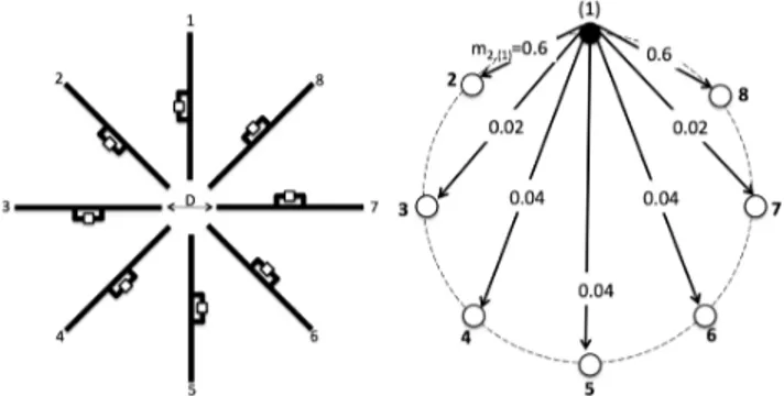
A circular alignment of eight T-match tags is finally analyzed (Fig. 10). The antennas are uniformly angularly spaced by 45 increments and the resulting grid shows a rotational symmetry. According to the study in [4], the corresponding impedance and admittance matrices are circulant which means that the diagonal elements are all the same and the sum of the elements of each row or column is a constant. Hence, under the usual assumption of broadside and circular-polarized illumination, so that
, the following identity holds , for any and therefore the modulation depths are simply
(33) where is the self network admittance of the system. For this kind of arrangement the cross-link interactions become re-ciprocal.
Fig. 10(b) shows the values in case the tag is acting as talker. Any other configuration is simply an angular shifted replica of the case.
Also in this configuration not all the tags will receive data signals with enough modulation depth ( 50%) to decode the message from the talker, but a multi-hop routing protocol could be implemented to have all the tags interconnected in an indirect way. For instance the connection among tag 1 and tag 5 may be achieved by a first link between tag 1 and tag 2 and hence by a
Fig. 10. A circular grid of equal dipoles with distance . right) Modulation index when the tag is talking.
second jump from tag 2 to tag 3, then from tag 3 to 4 and finally from 4 to 5.
VII. DISCUSSIONS ANDCONCLUSIONS
The feasibility, potentialities and limitations of passive Tag to Tag communications have been preliminary investigated by theoretical and numerical efforts. The possibility for the listener tag to decode signals coming from the talker is dependent on their mutual coupling as well as on their orientation with respect to the illuminator. Such a property is described by the mod-ulation depth parameter which strongly decays along with the distance among tags due to the interaction between direct- and cross-links. The modulation depth may be improved by a proper choice of the antenna’s impedance that directly accounts for the T2T coupling, following the Hermite impedance condition. In this case the modulation depth could be theoretically tuned up to 100% at a specific distance among tags and more in general the T2T range may be accordingly extended. Moreover in this condition also the BER among tags would result improved with respect to the standalone impedance matching. In any case, this kind of link is generally not symmetric, e.g., when the role of the talker and the listener are interchanged, the corresponding modulation depths may be different.
The considered examples of planar alignments demonstrate that the T2T range is mostly limited to the neighboring ele-ments and suffers from the mutual orientation among antennas. The communication range could be in principle extended to the whole grid by a multi-hop cooperative routing strategy. The most critical configurations are the collinear tags (
in the example with 3 3 grid) and the true possibility to establish the link will depend on the minimum modulation depth really required by the RFID chip to decode the informa-tion. It is worth noticing that in [13] there is the indication of a custom chip front-end able to respond to as low as 20% modu-lation index of the incoming signal. Even in this optimistic con-dition, the communication among collinear dipoles looks how-ever rather challenging and it is therefore better displacing tags so that they are facing, at least partially, as in the case of circular alignment. Looking ahead, the natural generalization of the con-sidered alignments are stochastic coalitions of passive tags, e.g., arrangements with no periodicity or regularity. At this purpose, (15) and (24) are suitable to be included into a statistic simulator to understand the achievable BER of such a complex system.
Tag to tag communication is definitely a new attractive, fas-cinating and completely open paradigm, with the potentiality to stimulate applications in pervasive and amorphous computing, wherein distributed and transparent sensing and computation are leading keywords. Nevertheless, a true implementation of the T2T links requires a change in the microchip hardware and new communication protocols. Some preliminary ideas about the latter issue may be found in [16] while the evolution of the microchip is still fully to be considered.
APPENDIX
A. Details About the Scavenged Powers in (17)
In case of ASK impedance modulation between
equi-prob-able states and , the averaged power
collected by any of the talker and the listener is
(34) with
(35) (36) the scavenged powers by the th chip during the two modulation
states. By considering that , the
final expressions in (16) and (17) are readily found.
B. Modulation Index of a Couple of Parallel Dipoles
For parallel half-wavelength tags the mutual impedance is predicted by the formulas in [10, p. 417] in terms of integral sines and cosines:
(37)
with , , .
By introducing the Exponential integral (29) the following relations ([11], 5.2.21, and 5.2.23) hold
(38) (39)
and . Therefore, by
com-bining above equations with (37) and with (26), the final expres-sion (28) is readily obtained.
ACKNOWLEDGMENT
The authors wish to thank P. Nikitin for inspiration and U. Muehlmann for technical informations.
REFERENCES
[1] G. Marrocco, “Pervasive electromagnetics: Sensing paradigms by pas-sive RFID technology,” IEEE Wireless Commun., vol. 17, no. 6, pp. 10–17, Dec. 2010.
[2] P. V. Nikitin, K. V. S. Rao, and S. Lam, “RFID paperclip tags,” in Proc. IEEE Int. Conf. on RFID, 2011, pp. 162–169.
[3] P. Nikitin, S. Ramamurthy, R. Martinez, and K. V. S Rao, “Passive tag to tag communications,” in Proc. IEEE Int. Conf. on RFID, 2012, pp. 177–184.
[4] G. Marrocco, “RFID grids: Part I—Electromagnetic theory,” IEEE Trans. Antennas Propag., vol. 59, no. 3, pp. 1010–1026, Mar. 2011. [5] S. Caizzone and G. Marrocco, “RFID grids: Part
II—Experimenta-tions,” IEEE Trans. Antennas Propag., vol. 59, no. 8, pp. 2896–2904, Aug. 2011.
[6] J.-S. Park, J.-W. Jung, and S.-Y. Ahn et al., “Extending the interro-gation range of a passive UHF RFID system with an external contin-uous wave transmitter,” IEEE Trans. Instrum. Meas., vol. 59, no. 8, pp. 2191–2197, Aug. 2010.
[7] F. Fuschini, C. Piersanti, F. Paolazzi, and G. Falciasecca, “Analytical approach to the backscattering from UHF-RFID transponder,” IEEE Antennas Wireless Propag. Lett., vol. 7, pp. 33–35, 2008.
[8] D. M. Dobkin, The RF in RFID: Passive UHF RFID in Practice. Amsterdam: Elsevier, 2007.
[9] U. Karthaus and M. Fischer, “Fully integrated passive UHF RFID transponder with 16.7 minimum RF input power,” IEEE J. Solid State Circ., vol. 38, no. 10, pp. 1602–1608, Oct. 2003.
[10] C. A. Balanis, Antenna Theory: Analysis And Design. New York: Wiley, 1997.
[11] M. Abramowitz and I. A. Stegun, Handbook of Mathematical Func-tions. Washington, DC: US National Bureau of Standards, 1965. [12] K. V. S. Rao, P. V. Nikitin, and S. F. Lam, “Impedance matching
con-cepts in RFID transponder design,” in Proc. 4th IEEE Workshop on Automatic Identification Advanced Technologies, 2005, pp. 39–42. [13] L. Zhongqi, Z. Chun, L. Yongming, and W. Zhihua, J. Semiconductors,
vol. 30, no. 9, p. 95005-1:4, Sept. 2009.
[14] G. Marrocco, “The art of UHF RFID antenna design: Impedance matching and size-reduction techniques,” IEEE Antennas Propag. Mag., vol. 50, no. 1, pp. 66–79, Feb. 2008.
[15] S. Haykin, Communication Systems. New York: Wiley, 1994. [16] INTERMEC IP Corp., “Stochastic Communication Protocol Method
and System for RFID Tags Based on Coalition Formation, Such as Tag-to-Tag Communication,” U.S. patent application 20080252424, Oct. 16, 2008.
Gaetano Marrocco (M’98) was born in Teramo,
Italy, on August 29, 1969, He received the Laurea degree in electronic engineering (cum laude and Academic Honour) and the Ph.D. degree in applied electromagnetics from the University of L’Aquila, Italy, in 1994 and 1998, respectively.
In 1994, he was at the University of Illinois at Ur-bana-Champaign as a Postgraduate Student. In 1999, he was a Visiting Researcher at the Imperial College in London, U.K. In 2008, he joined the Ph.D. pro-gram of the University of Grenoble (FR). Since 1997, he has been a Researcher at the University of Rome “Tor Vergata,” Rome, Italy, where he currently teaches electromagnetic technology for wireless systems and medical radio-systems, manages the Pervasive Electromagnetics Lab and is an Advisor in the Geo-Information Ph.D. program. In October 2010, he achieved the level of Associate Professor of Electromagnetics. His research is mainly directed to the modelling and design of broadband and ultra wideband (UWB) antennas and arrays as well as of sensor-oriented miniaturized antennas for Bio-medicine, Aeronautics and Radiofrequency Identification (RFID). He has been involved in several Space, Avionic, Naval and Vehicular programs of the Euro-pean Space Agency, NATO, Italian Space Agency, and the Italian Navy about the analysis and the design of non-conventional antennas and systems over plat-forms. He submitted 8 patents on broadband naval antennas and structural ar-rays, and on sensor RFID systems.
Prof. Marrocco currently serves as Associate Editor of the IEEE ANTENNAS ANDWIRELESSPROPAGATIONLETTERS, Vice-Chair of the Italian delegation URSI Commission D: Electronics and Photonics, and as member of Technical Program Committee of IEEE RFID, IEEE IMS and ISABEL. In 2008 he was the General Chairman of the first Italian multidisciplinary scientific workshop on RFID: RFIDays-2008: Emerging Technology for Radiofrequency Identifi-cation. He was the Co-Chair of the RFIDays-2010 International Workshop in Finland and Chairman of the Local Committee of the V European Conference on Antennas and Propagation. He is currently serving as TCP Chair of the 2012 IEEE-RFID TA in Nice, France.
Stefano Caizzone received the M.Sc. degree in
telecommunications engineering from the University of Rome “Tor Vergata” in 2009 and he is currently part-time working toward the Ph.D. degree.
His main research interests concern small antennas for RFIDs and navigation, antenna arrays and grids with enhanced sensing capabilities. He is now with the Antenna Group, Institute of Communications and Navigation of the German Aerospace Center (DLR), Wessling, Germany, where he is responsible for the development of innovative miniaturized antennas.